Table of Contents
Advertisement
Quick Links
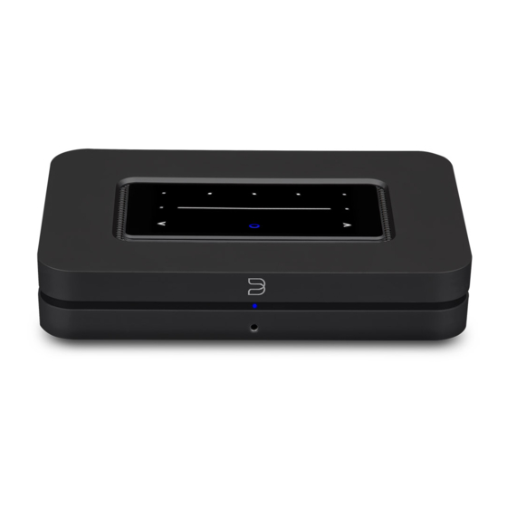
Instrukcja montażu interfejsu PCB dla Bluesound NODE
PCB interface assembly instructions for Bluesound NODE
Zdemontuj tylną osłonę podważając ją we
wskazanych miejscach. Osłona jest
mocowana na magnes.
Remove the rear cover by pulling it at the
indicated places. This cover is attached
with a magnet.
Wykręć dwie górne wskazane śruby.
Remove top two indicated screws.
Podnieś górną część obudowy odchylając
ją wyłącznie od tyłu urządzenia „jak
książkę", aż nie usłyszysz wyraźnych i
głośnych „kliknięć". Potem podnoś ją dalej
ostrożnie do góry uważając by nie zerwać
taśm i kabli.
Lift the upper part of the housing by tilting
it only from the back of the device „like a
book", until you hear loud "clicks". Then
lift it upwards, being
careful not to break the tapes and cables
.
Połóż ostrożnie górną część obudowy
obok, uważając na taśmę i kable. Nie
rozłączaj ich, gniazda są zabezpieczone
masą klejącą.
Put the upper case carefully next to it. Do
not disconnect cables, the sockets are
secured with adhesive.
Strona / Page 1
Advertisement
Table of Contents

Related Manuals for Bluesound NODE


Summary of Contents for Bluesound NODE
- Page 1 Instrukcja montażu interfejsu PCB dla Bluesound NODE PCB interface assembly instructions for Bluesound NODE Zdemontuj tylną osłonę podważając ją we wskazanych miejscach. Osłona jest mocowana na magnes. Remove the rear cover by pulling it at the indicated places. This cover is attached with a magnet.
- Page 2 Odłącz małe i duże gniazdo. Możesz wykorzystać do tego dłuższe szczypce. Następnie odkręć cztery wskazane strzałkami śruby mocujące. Disconnect the small and large socket. You can use longer pliers for this. Then remove screws indicated by the arrows. Odkręć na tylnym panelu wskazane śruby. Remove screws on the back panel.
- Page 3 Przykręć moduł 4 śrubami – dodatkowy element usztywniający powinien docisnąć zaślepkę gniazda. Podłącz 4-pinowy kabel. Mały kabel 2-pinowy zostaw niepodłączony. Screw the module with 4 screws – additional stiffening plate should press and hold the socket cover. Connect only 4-pin socket. Leave small 2-pin socket unconnected.
- Page 4 Dodatkowe informacje / additional information: Zasilanie wymagane przez moduł powinno mieścić się w zakresie od 5 do 5.1V. The power supply required by the module should be between 5 and 5.1V. Polaryzacja gniazda / Socket polarization: Specyfikacja / Specification. napięcie zasilania / supply voltage: 5V DC ...
Need help?
Do you have a question about the NODE and is the answer not in the manual?
Questions and answers