Table of Contents

Related Manuals for BENQ-SIEMENS EL71


Summary of Contents for BENQ-SIEMENS EL71
- Page 1 Release 1.0 Service Manual EL71 Level 1-3 Release Date Department Notes to change R 1.0 27.03.2006 BenQ Mobile CC S CES New document 02/2006 Technical Documentation TD_Repair_L1-L3_EL71_R1.0.pdf Page 1 of 56 Company Confidential 2006©BenQ...
-
Page 2: Table Of Contents
BenQ Service Equipment User Manual .................35 GRT Software: Functionality Configuration................36 GRT Software: Regular Usage ....................38 International Mobile Equipment Identity, IMEI..............43 General Testing Information....................44 10 Introduction of Service Repair Documentation Level 3 (basic) – EL71......50 02/2006 Technical Documentation TD_Repair_L1-L3_EL71_R1.0.pdf Page 2 of 56 Company Confidential 2006©BenQ... -
Page 3: Key Feature
Release 1.0 1 Key Feature • Tri – Band GSM 900/1800/1900 System • GPRS/EDGE Multislot class 10 • Vocoders FR, HR, EFR, AMR • Li-Ion 570 mAh Battery • Up to 300h Stand – by Time • Up to 300min Talking Time •... -
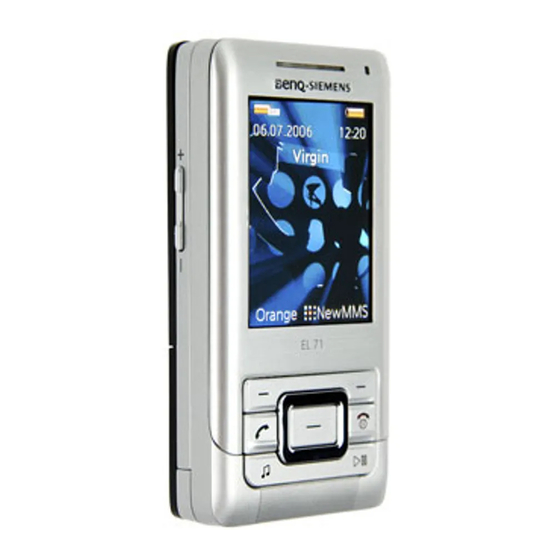
Page 4: Unit Description Of El71
Release 1.0 2 Unit Description of EL71 EL71 is a Slider mobile phone with a 2 inch QVGA Display and a semiautomatic slider system. The cases are molded painted plastic parts and die-casted metal parts with painted surface. On one plastic part is glued an anodized aluminium cover. -
Page 5: Exploded View Of El71
Release 1.0 3 Exploded View of EL71 02/2006 Technical Documentation TD_Repair_L1-L3_EL71_R1.0.pdf Page 5 of 56 Company Confidential 2006©BenQ... -
Page 6: Disassembly Of El71
Release 1.0 4 Disassembly of EL71 All repairs as well as disassembling and assembling have to be carried out in an ESD protected environment and with ESD protected equipment/tools. For all activities the international ESD regulations have to be considered. - Page 7 Release 1.0 Step 3 Remove Battery. Step 4 Remove screws by using the Torque – Screwdriver T5+. Step 5 Remove the Flashlight – Cover by using Tweezers. 02/2006 Technical Documentation TD_Repair_L1-L3_EL71_R1.0.pdf Page 7 of 56 Company Confidential 2006©BenQ...
- Page 8 Release 1.0 Step 6 Remove Rear Cover incl. Ringer. Step 7 Remove Lower Case Shell. Step 8 Remove Sheet Metal Battery Pocket by using Tweezers. 02/2006 Technical Documentation TD_Repair_L1-L3_EL71_R1.0.pdf Page 8 of 56 Company Confidential 2006©BenQ...
- Page 9 Release 1.0 Step 9 Disconnect Flex Cable from the PCB by using Tweezers carefully. Step 10 Disconnect Flex Cable from the PCB by using Tweezers carefully. Step 11 Take out partly the PCB by using Alternative Opening Tool. 02/2006 Technical Documentation TD_Repair_L1-L3_EL71_R1.0.pdf Page 9 of 56 Company Confidential...
- Page 10 Release 1.0 Step 12 Disconnect the Flex Cable from the lower side of the PCB by using Tweezers very carefully. Step 13 Step 14 Take out the end of the Flex Cable which fixtures the Side – Key. 02/2006 Technical Documentation TD_Repair_L1-L3_EL71_R1.0.pdf Page 10 of 56 Company Confidential...
- Page 11 Release 1.0 Step 15 Take out the end of the Flex Cable which fixtures the other Side – Key. Step 16 Now you can push the Side – Keys easily out of the side – key – frame. Step 17 Remove the Microphone by using Tweezers carefully.
- Page 12 Release 1.0 Step 18 Remove the Battery Connector by using Tweezers. Step 19 Remove the Antenna by using Tweezers. Step 20 Remove screws by using the Torque – Screwdriver T5+. 02/2006 Technical Documentation TD_Repair_L1-L3_EL71_R1.0.pdf Page 12 of 56 Company Confidential 2006©BenQ...
- Page 13 Release 1.0 Step 21 The Flex Cable is glued to the Lower Case. Remove it with Tweezers very carefully and take care, that it doesn’t rip! Step 22 Now you can separate the Lower Case from the Slider Plate. Direct the Flex Cable through the Out cut of the Lower Case.
- Page 14 Release 1.0 Step 24 Remove the keypad by fixing the Alternative Opening Tool at the front side of the keypad. Step 25 Remove the Keypad MMI. Be very careful! Step 26 Direct the Flex Cable through the Cut Out of the Lower Case.
- Page 15 Release 1.0 Step 27 Remove the Antenna Cap. Step 28 Step 29 Remove screws by using the Torque – Screwdriver T5+. 02/2006 Technical Documentation TD_Repair_L1-L3_EL71_R1.0.pdf Page 15 of 56 Company Confidential 2006©BenQ...
- Page 16 Release 1.0 Step 30 Remove the Slider Cover. Step 31 Take the Slider Plate out of the Upper Case. Step 32 To avoid scratches it is mandatory to place a protection foil onto the Display!!! 02/2006 Technical Documentation TD_Repair_L1-L3_EL71_R1.0.pdf Page 16 of 56 Company Confidential 2006©BenQ...
- Page 17 Release 1.0 Step 30 Remove the Keypad by using Tweezers. Step 31 Remove Earphone by using Tweezers. Step 32 Remove Vibramotor by using Tweezers. 02/2006 Technical Documentation TD_Repair_L1-L3_EL71_R1.0.pdf Page 17 of 56 Company Confidential 2006©BenQ...
- Page 18 Release 1.0 Step 33 Remove the Light Guide LED by pushing it outside of the frame. Step 34 Remove screws by using Screwdriver Step 35 Remove the Slider Cover. 02/2006 Technical Documentation TD_Repair_L1-L3_EL71_R1.0.pdf Page 18 of 56 Company Confidential 2006©BenQ...
- Page 19 Release 1.0 Step 36 Remove the Slider Sticks. Step 37 Step 38 Remove the Keypad MMI. 02/2006 Technical Documentation TD_Repair_L1-L3_EL71_R1.0.pdf Page 19 of 56 Company Confidential 2006©BenQ...
- Page 20 Release 1.0 Step 30 Disconnect the Display Module from the Slider Plate. Step 31 Disconnect the Display Flex Cable from Keypad MMI. Step 32 Loosening the Flex Cable from the Slider Plate. 02/2006 Technical Documentation TD_Repair_L1-L3_EL71_R1.0.pdf Page 20 of 56 Company Confidential 2006©BenQ...
- Page 21 Release 1.0 Step 30 Direct the Flex Cable through the Cut Out of the Slider Plate. Step 31 Now you can remove the Flex Cable completely from the Slider Plate. Step 32 02/2006 Technical Documentation TD_Repair_L1-L3_EL71_R1.0.pdf Page 21 of 56 Company Confidential 2006©BenQ...
-
Page 22: Assembly Of El71
Lower Slider Case Shell Keypad Front cover Screws Sticks Slider Plate Assembly of EL71 Step 1 Assemble the Flex Cable onto the Slider Plate. Step 2 Direct the Flex Cable through the Cut Out of the Slider Plate. 02/2006 Technical Documentation TD_Repair_L1-L3_EL71_R1.0.pdf... - Page 23 Release 1.0 Step 3 Assemble the Display Module onto the Slider Plate. Step 4 Connect the Flex Cable from the Keypad MMI with the Connector on the Slider Plate. Step 5 Assemble the Slider Sticks. 02/2006 Technical Documentation TD_Repair_L1-L3_EL71_R1.0.pdf Page 23 of 56 Company Confidential 2006©BenQ...
- Page 24 Release 1.0 Step 6 Assemble the Slider Cover. Step 7 Place screws by using the Torque – Screwdriver T3+. Step 8 Assemble the Earphone into the frame by using Tweezers. 02/2006 Technical Documentation TD_Repair_L1-L3_EL71_R1.0.pdf Page 24 of 56 Company Confidential 2006©BenQ...
- Page 25 Release 1.0 Step 9 Assemble the Vibramotor into the frame by using Tweezers. Step 10 Assemble the Light Guide LED by using Tweezers. Step 11 Assemble the Keypad MMI by using Tweezers. 02/2006 Technical Documentation TD_Repair_L1-L3_EL71_R1.0.pdf Page 25 of 56 Company Confidential 2006©BenQ...
- Page 26 Release 1.0 Step 12 Remove the Display Foil from the Display. Step 13 Assemble the Slider Plate into the Upper Case. Step 14 02/2006 Technical Documentation TD_Repair_L1-L3_EL71_R1.0.pdf Page 26 of 56 Company Confidential 2006©BenQ...
- Page 27 Release 1.0 Step 15 Place screws by using the Torque – Screwdriver T5+. Step 16 Assemble the Antenna Cap. Step 17 Direct the Flex Cable of the Keypad MMI through the Cut Out of the Lower Case. 02/2006 Technical Documentation TD_Repair_L1-L3_EL71_R1.0.pdf Page 27 of 56 Company Confidential...
- Page 28 Release 1.0 Step 15 Fix the Keypad MMI into the given frame. Step 16 Assemble the Keypad onto the Keypad MMI. Step 14 Direct the Flex Cable of the Slider Plate through the Cut Out of the Lower Case. Take care of the Flex Cable. 02/2006 Technical Documentation TD_Repair_L1-L3_EL71_R1.0.pdf...
- Page 29 Release 1.0 Step 15 Place screws by using the Torque – Screwdriver T5+. Step 16 Assemble the Battery Connector by using Tweezers. Step 17 Assemble the Microphone by using Tweezers. 02/2006 Technical Documentation TD_Repair_L1-L3_EL71_R1.0.pdf Page 29 of 56 Company Confidential 2006©BenQ...
- Page 30 Release 1.0 Step 18 Assemble the Antenna by using Tweezers. Step 19 Lay the Camera Flex Cable into the Lower Case. Take care that it has the correct position! Step 20 Assemble the Side key into the frame by using Tweezers. 02/2006 Technical Documentation TD_Repair_L1-L3_EL71_R1.0.pdf...
- Page 31 Release 1.0 Step 21 To fix the Side Key you have to assemble the end of the Flex Cable in the given frame. Step 22 Assemble the Side key into the frame by using Tweezers. Step 23 To fix the Side Key you have to assemble the end of the Flex Cable in the given frame.
- Page 32 Release 1.0 Step 21 Assemble the Sheet Metal Battery Pocket. Step 22 Assemble the PCB into the Lower Case. Step 23 Connect the Flex Cable of the Keypad MMI with the PCB. 02/2006 Technical Documentation TD_Repair_L1-L3_EL71_R1.0.pdf Page 32 of 56 Company Confidential 2006©BenQ...
- Page 33 Release 1.0 Step 21 Assemble the Rear Cover incl. Ringer. Step 22 Assemble the Flashlight Cover by using Tweezers. Step 23 Assemble the Lower Case Shell. 02/2006 Technical Documentation TD_Repair_L1-L3_EL71_R1.0.pdf Page 33 of 56 Company Confidential 2006©BenQ...
- Page 34 Release 1.0 Step 21 Place screws by using the Torque – Screwdriver T5+. Step 22 Assemble Battery. Step 23 Assemble Battery Cover. 02/2006 Technical Documentation TD_Repair_L1-L3_EL71_R1.0.pdf Page 34 of 56 Company Confidential 2006©BenQ...
-
Page 35: Benq Service Equipment User Manual
Release 1.0 5 BenQ Service Equipment User Manual Introduction Every LSO repairing BenQ handset must ensure that the quality standards are observed. BenQ has developed an automatic testing system that will perform all necessary measurements. This testing system is known as: BenQ Mobile Service Equipment •... -
Page 36: Grt Software: Functionality Configuration
Release 1.0 6 GRT Software: Functionality Configuration Select „Settings >> SWUP / JPICS” Sep 1: Proceed as follows Step 2: Select all required Variants you need to repair (click onto the “+” in front of the product name. Check Com-Port setting. If necessary change it Check speed setting. - Page 37 Release 1.0 Connect to GRM Server Step 3: • Choose in the section „GRM” the „Connect to GRM Database“ functionality Enter your GRT-Username and Password into this fields Activate always both boxes if you connect to the database. Start with “Connect” It you IT infrastructure parameter have changed, use this button to move to the configuration mask...
-
Page 38: Grt Software: Regular Usage
Release 1.0 7 GRT Software: Regular Usage Select the section SWUpdate Step 1: Choose the area you want to work with Step 2: • Personal Repair Personal Repair is always accessible. Basis for the decision if a SW-Update is authorised by Siemens is the so called Service Release-Table. Example: Mobile Phone has already SW50. - Page 39 Release 1.0 Window explanation This general explanation is valid for all SW-Update channels (Personal Repair, Operator SWAP, Operator SWUpdate) After using „Check Variant“ Phone IMEI- Number will be shown here Window to select the mobile phone CPU Shows the different SW –Versions a) SW inside the mobile phone b) Version of Service Release Table c) Version of Master Table SW...
- Page 40 Release 1.0 Case 1: Personal Repair (green) Step 1: Carry out step 1 – 4 to start SW-Update. Select the mobile phone CPU type Start SW-Update Choose if customer data shall be erased. If “Yes” activate the boxes in front of xfs and mapping 1.1.1.1.1.1.4 Read out phone...
- Page 41 Release 1.0 Case 2: Operator SWAP (red) Step 1: Carry out step 1 – 4 to start SW-Update. Select the mobile phone CPU type Start SW-Update Choose if customer data shall be erased. If “Yes” activate the boxes in front of xfs and mapping 1.1.1.1.1.1.3 Read out phone...
- Page 42 Release 1.0 Case 3 Operator SWUpdate (blue) Step 1: Carry out step 1 – 4 to start SW-Update. Select the mobile phone CPU type Start SW-Update Choose if customer data shall be erased. If “Yes” activate the boxes in front of xfs and mapping 1.1.1.1.1.1.2 Read out phone...
-
Page 43: International Mobile Equipment Identity, Imei
2 digits. 6 digits have been allocated for the equipment serial number for manufacturer and the last digit is spare. EL71 series IMEI label is accessible by removing the battery. Re – use of IMEI label is possible by using a hair – dryer to remove the IMEI label. -
Page 44: General Testing Information
Release 1.0 9 General Testing Information General Information The technical instruction for testing GSM mobile phones is to ensure the best repair quality. Validity This procedure is to apply for all from Siemens AG authorized level 2 up to 2.5e workshops. Procedure All following checks and measurements have to be carried out in an ESD protected environment and with ESD protected equipment/tools. - Page 45 Release 1.0 Incoming check and check after assembling: !! Verify the customers fault description!! After a successful verification pass the defective item to the responsible troubleshooting group. If the fault description can not be verified, perform additional tests to save time and to improve repair quality.
- Page 46 Release 1.0 GSM Test: With the availability of the GRT Test /Alignment software, this tool has to be used to perform the outgoing test! >Connect the mobile/board via internal antenna (antenna coupler) and external antenna (car cradle/universal antenna clip) to a GSM tester >Use a Test SIM For Triple Band phones use a separate test case, if the test software allows only one handover.
- Page 47 Release 1.0 External Antenna Call from MS • GSM900 • Keyboard check • individual • high TCH check • second highest PCL • BS Power = -75 dBm • middle BCCH TX GSM Band 1 • high TCH • Frequency Error •...
- Page 48 Release 1.0 Annex 1 Test SIM Card There are two different “Test SIM Cards” in use: 1) Test SIM Card from the company “ORGA” Pin 1 number: 0000 PUK 1 12345678 Pin 2 number: 0000 PUK 2 23456789 2) Test SIM Card from the company “T-D1” Pin 1 number: 1234 76543210...
- Page 49 Release 1.0 Annex 2 Battery Date Code overview Varta Date code example N 9 A VA Year (N:2001, O:2002...) Supplier Code Month (1:Jan, 2:Feb,…9:Sep, O:Oct, N:Nov, D:Dec) (Maker’s marking) Revision Letter (A, B,…) Hitachi / Maxwell Date code example N 9 A MX Year (N:2001, O:2002...) Supplier Code Month (1:Jan, 2:Feb,…9:Sep, O:Oct, N:Nov, D:Dec)
-
Page 50: Introduction Of Service Repair Documentation Level 3 (Basic) - El71
The Service Partner has to ensure that every repaired mobile Phone is checked according to the latest released General Test Instruction document (both documents are available in the Technical Support section of the C-market). Check at least weekly C-market for updates and consider all EL71 related Customer Care Information EL71 Partnumber on IMEI label: S30880-S2620-#xxx , while # may be any letter (A-Z) and xxx may be any number from 100, 101, 102.. - Page 51 Release 1.0 List of available Level 3 (basic) parts Product Chipset Order Number Description CM EL71 X1510 L50634-Z93-C364 IO-JACK NANO 12-POL EL71 X1603 L50634-Z97-C458 CONNECTOR SIM CARD READER R65 SHORT EL71 X2201 L50634-Z97-C461 CONNECTOR BOARD TO BOARD 40-POL 1,5MM EL71...
- Page 52 Release 1.0 EL71 Board Layout Upper board side CONNECTOR BOARD TO BOARD 40-POL 1,5MM FILTER EMI IO-JACK NANO 12-POL Lower board side CONNECTOR CARDREADER TRANSFLASH HINGE CONNECTOR BOARD TO BOARD 40-POL 1MM CONNECTOR SIM CARD READER R65 SHORT CONNECTOR BOARD TO...
- Page 53 Release 1.0 SIM Card Problems Fault Symptoms Customer: Handset does not accept SIM card Back to customer SIM Card Problems without repair okay Watch for oxidation and Caused by customer damaged pads of the SIM Card reader SCRAP - has to be send separately to WSC Okay - check for twisted or...
- Page 54 Release 1.0 I/O Connector Problems Fault Symptoms Customer: Problems with external loudspeaker or microphone when using a car kit Problems with accessories connected at the IO connector Back to customer IO connector Problems without repair okay Watch for oxidation and Caused by customer damaged pads of the IO connector...
- Page 55 Release 1.0 Board to Board Connector Problems Fault Symptoms Customer: GRT: Display problems Keypad malfunction Keypad illumination problems Current measured failed Keypad malfunction Back to customer B to B connector problems without repair okay Watch for oxidation and caused by customer damaged pads of the B to B connector okay...
- Page 56 Release 1.0 Transflash Card Reader Problems Fault Symptoms Customer: Card Reader malfunction Back to customer Card Reader Problems without repair okay Watch for oxidation and caused by customer damaged pads of the Card Reader okay SCRAP - has to be send separately to WSC - check for twisted or okay...
Need help?
Do you have a question about the EL71 and is the answer not in the manual?
Questions and answers