Table of Contents
Advertisement
Quick Links
Advertisement
Table of Contents

Related Manuals for Omron LD-105CT


Summary of Contents for Omron LD-105CT
- Page 1 LD Cart Transporter User's Manual I612-E-07...
- Page 2 The information contained herein is the property of Omron Robotics and Safety Technologies, and shall not be reproduced in whole or in part without prior written approval of Omron Robotics and Safety Tech- nologies The information herein is subject to change without notice and should not be construed as a com- mitment by Omron Robotics and Safety Technologies The documentation is periodically reviewed and revised.
-
Page 3: Table Of Contents
Table of Contents Chapter 1: Introduction 1.1 Definitions 1.2 Product Description LD Platform Cart Transporter Cart Coupling Optional Components User-Supplied Components / System Requirements 1.3 Software Overview FLOW Core SetNetGo 1.4 How Can I Get Help? Related Manuals Support Including a DebugInfo File Chapter 2: Safety 2.1 Dangers, Warnings, and Cautions Alert Levels... - Page 4 Table of Contents Public Access Clearance Obstacles Safety Scanning Laser Emergency Stop Safety System Overspeed Faults 2.5 Intended and Non-intended Use Intended Use Non-Intended Use Platform Modifications 2.6 Battery Safety 2.7 Additional Safety Information Accidental Cart Separation Mobile Robot LD Safety Guide 2.8 Disposal Chapter 3: Setup Overview...
- Page 5 Table of Contents Marking Cart-Parking Goals on Floor 4.3 Configuring a Touchscreen Touchscreen Ethernet Setup Operating Modes Localization Goals Screen Logo Screensaver Display Language Contact Information 4.4 Acceleration, Deceleration, and Rotation Limits 4.5 Supplemental Information Laser Setup Chapter 5: Payloads 5.1 Safety Warning Label Drive Warning Light...
- Page 6 Table of Contents Center Pane Relocalization Choose Dropoff Mode Patrol Route Mode 7.2 Operator Panel E-Stop Button ON Button OFF Button Brake-release (BRAKE) Button Keyswitch LATCH Button UNLATCH Button 7.3 Other Controls and Indicators Light Discs and Beacon LD Platform Core Indicators Battery and Docking Station Chapter 8: Operation 8.1 Operating Environment...
- Page 7 Table of Contents Spare Battery Spare Carts Call Buttons/Door Boxes Acuity Localization High-Accuracy Positioning System Chapter 10: Maintenance 10.1 Safety Aspects While Performing Maintenance Electrical Hazards Burn Hazard Pinch Hazard Magnetic Field Hazards 10.2 Safety Measures Prior and After Maintenance 10.3 Lifting the Platform Safely Front Lifting Points Rear Lifting Area...
- Page 8 Table of Contents Obstacle Detection and Coupling Lasers Rear Sonar Units Sonar Controller Cart Latching Mechanism Light Discs Operator Panel Wheels and Tires Drive Assemblies Platform Casters Cleaning Casters on ESD Platforms LD Platform Cart Transporter Casters Cart Brake Release LD Platform Core E-Stop and Safety Laser Commissioning Chapter 11: Technical Specifications...
- Page 9 Revision History Revision Code Date Revised Content April, 2017 Original release March, 2017 Corrections and improvements. September, 2017 Corrections and improvements. November, 2017 Corrections and improvements. February, 2018 Corrections and improvements. February 2019 Corrections and improvements. April, 2021 Corrections and improvements. 14766-000 Rev H LD Cart Transporter User's Manual...
-
Page 11: Chapter 1: Introduction
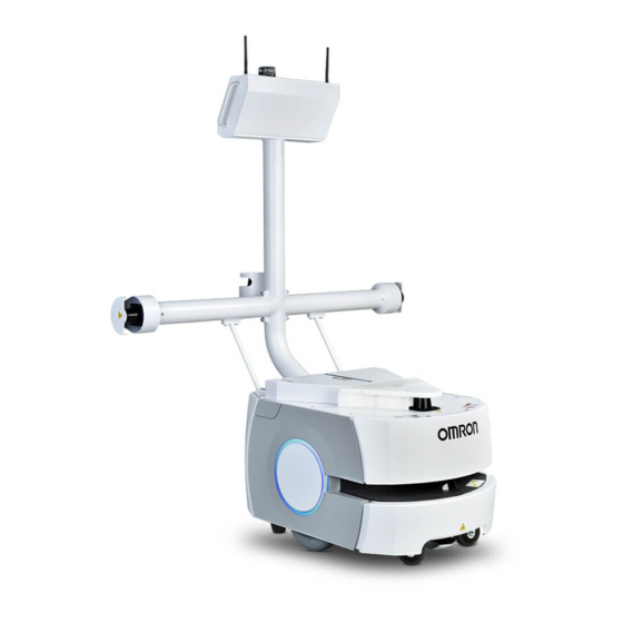
The LD Platform Cart Transporter is available in two models, designed to transport carts with a payload up to 105 kg (231 lb) for the LD-105CT and 130 kg (287 lb) for the LD-130CT plat- form. Where appropriate, differences between the models are called out. Otherwise, this manual applies to both LD Platform Cart Transporters. - Page 12 1.2 Product Description Figure 1-1. Cart and LD Platform Cart Transporter, Separate Figure 1-2. Cart and LD Platform Cart Transporter, Coupled LD Cart Transporter User's Manual 14766-000 Rev H...
-
Page 13: Ld Platform Cart Transporter
Chapter 1: Introduction LD-105CT LD-130CT Figure 1-3. LD Platform Cart Transporter Model Labels LD Platform Cart Transporter The LD Platform Cart Transporter is a mobile platform, designed for working around people while moving a cart. It is self-guided and self-charging, with an automated docking station. - Page 14 1.2 Product Description operates in a single plane, positioned at 200 mm (7.9 inches) above the floor. In most envir- onments, the sensor will provide highly-accurate data. Glass, mirrors, and other highly-reflective objects cannot be reliably detected by the laser. Cau- tion must be exercised when operating the AMR in areas that have these types of objects.
- Page 15 Chapter 1: Introduction What’s Included with an LD Platform Cart Transporter One fully-assembled platform The platform includes a safety scanning laser, a low front laser, two side lasers, a rear- facing laser, and two rear-facing sonar pairs. Each pair is one transmitter and one receiver.
-
Page 16: Cart
1.2 Product Description Cart The cart is a frame mounted on four casters, designed so that it can couple with an LD Plat- form Cart Transporter. Once coupled, the cart moves with the transporter. When the trans- porter arrives at the intended goal, it uncouples from the cart and leaves, while the cart remains at the goal. -
Page 17: User-Supplied Components / System Requirements
Chapter 1: Introduction Spare battery A spare battery can be used to minimize down-time. Swapping the battery for a fully- charged battery avoids taking the AMR out of service for more than a few minutes. Call/Door Boxes These allow an AMR to be requested from a remote location, or allow the AMR system to control an automated door, so the AMR can pass through it. - Page 18 1.3 Software Overview queuing of jobs for the AMRs remote I/O, if you are using it MobilePlanner (licensed) In order to have your AMR perform autonomous mobile activities, you need to make a map of its operating space, and configure its operating parameters. The MobilePlanner software is used to make this map and perform this configuration.
-
Page 19: Setnetgo
Support If, after reading this manual, you are having problems with your LD Platform Cart Trans- porter, contact your local Omron support. In the body of your e-mail message, provide your platform’s serial number and describe the problem you are having in as much detail as possible. -
Page 20: Including A Debuginfo File
1.4 How Can I Get Help? Including a DebugInfo File If the platform has been set up on a wireless network, skip to SetNetGo Access on page 21. Network Setup If the AMR has not been set up on a wireless network, a local area network will have to be set up on a separate PC, and configured to talk to the AMR over a TCP/IP port. - Page 21 Chapter 1: Introduction SetNetGo Access If the MobilePlanner software is available, use the SetNetGo interface within that software to access SetNetGo. Otherwise, open a web browser and enter the URL: https://1.2.3.4: You will be requested to confirm security certificates. Regardless of how you accessed SetNetGo, you should now have a window similar to the fol- lowing: 1.
-
Page 23: Chapter 2: Safety
Chapter 2: Safety 2.1 Dangers, Warnings, and Cautions Alert Levels There are three levels of alert notation used in our manuals. In descending order of import- ance, they are: DANGER: Identifies an imminently hazardous situation which, if not avoided, is likely to result in serious injury, and might result in fatality or severe property damage. -
Page 24: Falling Hazards
2.2 What to Do in an Emergency /Abnormal Situation Icon Meaning Icon Meaning This identifies a hazardous ESD situation. Falling Hazards DANGER: PERSONAL INJURY OR PROPERTY DAMAGE RISK The AMR can cause serious injury to personnel or damage to itself or other equipment if it drives off of a ledge, such as a loading dock, or down stairs. Physical Barriers The edge of a loading dock, the entrance to downward stairs, or any other substantial drop that is within the AMR’s expected operating area should be physically marked so that the... -
Page 25: Releasing An E-Stop
Chapter 2: Safety Version Information: The LD-130CT has a high gear ratio, and is difficult to move, even with the brakes released. Releasing an E-Stop CAUTION: PERSONAL INJURY OR PROPERTY DAMAGE RISK If the AMR’s E-Stop is triggered, ensure that the cause of the E-Stop is resolved, and all surrounding areas are clear releasing the E-Stop. -
Page 26: General Hazards
Do not continue to run the AMR after hair, yarn, string, or any other items have become wound around the platform’s axles, casters, or wheels. Do not use parts not authorized by Omron Robotics and Safety Technologies Do not turn on the AMR without the antennas in place. -
Page 27: Pinch And Entanglement Hazards
Chapter 2: Safety Avoid shorting the battery terminals. Do not use any charger not supplied by Omron Robotics and Safety Technologies If any liquid is spilled on the AMR, power off the AMR, clean up all possible liquid, and allow the AMR to air dry thoroughly before restoring power. -
Page 28: Magnetic Field Hazards
It is the end-user’s responsibility to ensure that all personnel who will work with or around AMRs have attended an appropriate Omron training course and have a working knowledge of the system. The user must provide any necessary additional training for all personnel who will be working with the system. -
Page 29: Payload Movement And Transfer
Chapter 2: Safety Understand the guides Will work in the manner specified by the guides Payload Movement and Transfer Monitoring and confirmation of the status of AMR payload movement and transfer to or from facility equipment is the end-user’s responsibility. Payload transfer problems must trigger an AMR E-Stop, preventing the AMR from moving until an Operator has resolved the problem and confirmed that the system is safe to use. -
Page 30: Traffic Control
2.4 Environment dynamic X, Y, Theta, size, and path-planning information with each other. AMRs then factor this data into their obstacle avoidance. This is not a physical method of preventing collisions, such as interlocked gateways or barriers. Ultimately, it is the end-user/integrator's respons- ibility to provide a physical method of preventing collisions. -
Page 31: Clearance
Chapter 2: Safety Clearance The LD Platform Cart Transporter is designed to operate in an environment that is generally level and has no doors or other restricted areas too narrow for the platform and cart. It is the user’s responsibility to ensure that adequate clearance is maintained on each side of the AMR, so that a person cannot get trapped between the AMR and a wall or other fixed object. -
Page 32: Intended And Non-Intended Use
2.5 Intended and Non-intended Use button is pressed) and the brake release is overridden, the safety system cannot stop the LD Platform since power to the motors has already been cut off. Once the fault condition is resolved, the safety system will stop reporting safety fault to the motion controllers, and the normal start-up process will initiate. -
Page 33: Non-Intended Use
The body of the AMR must not come into contact with liquids. The drive wheels can tolerate damp floors, but the body of the AMR must remain dry. If there is any doubt concerning the application, ask your local Omron support to determine if it is an intended use or not. -
Page 34: Platform Modifications
In the unlikely event that the cart becomes unlatched from the platform while in motion, the brakes are designed to stop the cart within six feet. Mobile Robot LD Safety Guide Your local Omron support provides other sources for more safety information: LD Cart Transporter User's Manual 14766-000 Rev H... -
Page 35: Disposal
WEEE (Waste Electronics and Electrical Equipment). All electrical and elec- tronic products should be disposed of separately from the municipal waste system via des- ignated collection facilities. For information about disposal of your old equipment, contact your local Omron support. 14766-000 Rev H LD Cart Transporter User's Manual... -
Page 37: Chapter 3: Setup
Chapter 3: Setup Overview In general, setup is the physical preparation of the platform and cart, and physically marking parking goal locations on your facility floor. Marking the parking goals on the floor is for human use. An LD Platform Cart Transporter will not use those markings, although we recom- mend you mark them in any case to prevent someone from placing something there that would prevent a cart from being parked. -
Page 38: Ld Platform Cart Transporter
3.1 Transport and Storage The containers must always be shipped and stored in an upright position in a clean, dry area that is free from condensation. Do not lay the containers on their sides or any other non- upright position. LD Platform Cart Transporter The LD Platform Cart Transporter system, which includes a cart, is shipped in one crate, along with the docking station, joystick, and all components except for the battery. -
Page 39: Before Unpacking
If the items received do not match the packing slip, or are damaged, do not sign the receipt. If the items received do not match your order, please contact your local Omron support immediately. Retain the containers and packing materials. These items may be necessary to settle claims or, at a later date, to relocate the equipment. - Page 40 3.3 Unpacking Figure 3-1. Battery Shipping Container The battery box measures 311 x 540 x 457 mm (12.25 x 21.25 x 18 inches). NOTE: The battery weighs 19 kg (42 lbs). There are recesses at the front and the back of the battery, to aid in lifting it. LD Cart Transporter User's Manual 14766-000 Rev H...
-
Page 41: Ld Platform Cart Transporter
Chapter 3: Setup LD Platform Cart Transporter Figure 3-2. Cart and LD Platform Cart Transporter in Crate The transporter crate measures 1257 x 1149 x 1645 mm (49.50 x 45.25 x 64.75 inches). Removing the Front Panel The front panel of the transporter crate doubles as a ramp, for rolling the platform off of the crate base. - Page 42 3.3 Unpacking Figure 3-3. Spring-loaded Latch 2. Remove the front panel, and set it aside. This will be used as a ramp, to roll the platform off of the crate base. Removing the Upper Body of the Crate 1. There are six lag bolts and washers around the base of the crate, two in the rear and two on each side.
- Page 43 Chapter 3: Setup CAUTION: PERSONAL INJURY OR PROPERTY DAMAGE RISK Due to the weight and size of the crate upper body, and the potential to damage the platform during this step, two people should work together to remove it. Removing the Cart The cart is secured under a wooden panel and a cardboard box. 1.
-
Page 44: Repacking For Relocation
3.4 Setting Up an LD Platform Cart Transporter Removing the Crate Braces 1. Remove the top brace by releasing the four spring-loaded latches, two on either side of the brace. 2. Remove the front brace by releasing the two spring-loaded latches, one on either side of the brace. -
Page 45: Rolling The Ld Platform Cart Transporter Off Of The Crate Base
Chapter 3: Setup Rolling the LD Platform Cart Transporter off of the Crate Base 1. Install the crate front onto the crate base, to serve as a ramp. There are two hanger bolts that stick up out of the front of the crate base. These fit into two holes in the end of the ramp. - Page 46 3.4 Setting Up an LD Platform Cart Transporter Figure 3-8. Wheel Pin Hole Location For each side of the platform: a. Remove the side cover a small distance from the platform. Refer to Removing Covers on page 159. The light disc PCA cable will still be attached. b.
-
Page 47: Installing The Battery
Chapter 3: Setup e. Lower the wheel to the floor. The wheels are spring-loaded, and the wheel brakes will be on. f. Put the side cover next to the platform, and attach the light disc cable to the light disc PCA. g. - Page 48 3.4 Setting Up an LD Platform Cart Transporter Figure 3-10. Pulling the Bottom of the Rear Cover Out Figure 3-11. Lowering the Rear Cover LD Cart Transporter User's Manual 14766-000 Rev H...
- Page 49 Chapter 3: Setup Refer to Removing and Installing LD Platform Cart Transporter Covers in the Maintenance sec- tion for cover removal and installation. 1. Remove the inner rear platform cover. a. Pull the bottom of the cover away from the platform chassis. This is easiest if you grip it with two hands, toward the center.
- Page 50 3.4 Setting Up an LD Platform Cart Transporter Figure 3-13. Lifting the Battery The connectors for power and data go toward the rear of the platform. 4. Attach the battery power and data cables to the connectors at the rear of the battery. Figure 3-14.
-
Page 51: Installing The Docking Station
Chapter 3: Setup Installing the Docking Station The automated docking station can be used for either manual or automated charging of your LD Platform Cart Transporter's battery. The docking station sits on the floor. It can be attached to a wall with the wall bracket, attached directly to the floor with screws through its base, or it can sit stand-alone on the floor with the floor plate, all of which will keep the docking station from moving when the trans- porter docks. - Page 52 3.4 Setting Up an LD Platform Cart Transporter 3x Ø6 8x 25 18x Ø6 98 ± 20 Figure 3-15. Docking Station, Wall Mount Bracket Detail, (A) Through Hole (units are in mm) 2. Screw the two shoulder bolts, each with a washer, into the rear of the docking station. The shoulder bolts are M5 x 4, stainless steel.
- Page 53 Chapter 3: Setup Figure 3-16. Rear View of Docking Station with Shoulder Bolts 3. Lower the docking station down, so the two shoulder bolts on the back of the docking station slide into the bracket, to secure the docking station to the wall. Floor-mount, without Floor Plate NOTE: Because this method permanently attaches the dock to the floor, it may be subject to building code regulations.
- Page 54 3.4 Setting Up an LD Platform Cart Transporter station. Attaching the Floor Plate Refer to the following figures. 1. Tip the docking station onto its back, so you can access the underside. 2. Remove the two lowest screws (M4 x 12 flat-head), if present. In the following figure, these screws are circled.
- Page 55 Chapter 3: Setup Figure 3-18. Docking Station, Mounted on Floor Plate Figure 3-19. Docking Station Floor Plate Dimensions (units are in mm) 14766-000 Rev H LD Cart Transporter User's Manual...
-
Page 56: Installing The Cart Brake Release
3.5 Installing the Cart Brake Release Power On Install the power cord and turn the power switch to ON. The power switch is next to the power plug. The blue power LED indicator should light. Docking Station Contact Adjustment The contacts on the docking station have five height settings. The station is shipped with the height in the highest setting. -
Page 57: Installation
Chapter 3: Setup Figure 3-21. Cart Caster Brake, Showing Spring and Pin To allow an Operator to release the cart brakes when there is no cart LD Platform Cart Trans- porter present, each cart comes with a brake-release cable and lever, similar to a bicycle hand brake, that releases the cart brakes when squeezed. - Page 58 3.5 Installing the Cart Brake Release Figure 3-22. Brake-release Lever CAUTION: PERSONAL INJURY RISK It is important that the brake-release handle be mounted in an ergonomically- suitable location, so an Operator can repetitively release the brakes without risk- ing injury. The actual mounting location and procedure for the brake-release handle are not covered here due to the variability that is possible in cart structure designs.
- Page 59 Chapter 3: Setup Figure 3-23. Thru-hole for Brake-release Cable, (A) 6 mm diameter (0.25 in.) pass-through hole for brake cable, through rear frame tube Figure 3-24. Thru-holes for Brake-release Cable, Plate Removed 14766-000 Rev H LD Cart Transporter User's Manual...
- Page 60 3.5 Installing the Cart Brake Release Callout Description Callout Description Route brake-release cable up to Secure brake-release cable to brake lever saddle tie 6 mm diameter (0.25 in.) hole through rear tube wall After the brake-release lever has been mounted on the cart payload: 1.
-
Page 61: Adjustment
Chapter 3: Setup 4. Run the inner wire of the cable around the pulley, through the bushing in the actuator bar, and through the lever cable clamp. 5. Pull the inner wire tight enough to remove slack, and tighten the lever cable clamp on 6. -
Page 63: Chapter 4: Configuration
Chapter 4: Configuration The LD Platform Cart Transporter comes with firmware and on-board software installed. Configuration of an LD Platform Cart Transporter is done using the MobilePlanner software. Configuration includes generation of the map that the AMR will use for navigation. The cart parking goals need to be added to that map. - Page 64 4.1 Settings and Configuration Figure 4-1. (A) PC, (B) Cat 5 Ethernet, and (C) Maintenance Access Panel The LD Platform core is preset and tested on a Class-C network (netmask for all ports 255.255.255.0). The Maintenance Ethernet port is set to IP address 1.2.3.4 and the wireless IP comes set with an AP-based ("managed") SSID of “Wireless Network”, unsecured.
-
Page 65: Setting Up Wireless Ethernet
Chapter 4: Configuration Setting Up Wireless Ethernet The SetNetGo OS is used to configure the platform wireless Ethernet, among other things. Refer to the FLOW Core User's Guide for details. NOTE: Although an LD Platform Cart Transporter is capable of working without wireless Ethernet if there are no other AMRs that it needs to know about (and to avoid), that is the exception. - Page 66 4.1 Settings and Configuration Security Settings Encryption: Disabled WEP 64-bit WEP 128-bit TKIP/RC4 CCMP/AES TKIP/CCMP/AES Authentication: OPEN WPA-PSK WPA2-PSK WEP Key Number (Key 1 - Key 4) WEP Keys WPA/WPA2-PSK PSK-Type (Passphrase or Raw Hex) Click Apply for your changes to take effect. Wireless Coverage The AMR must have wireless coverage for multi-AMR installations, or in areas where you wish to send new commands to or receive status updates from the AMR.
-
Page 67: Mapping
Chapter 4: Configuration 0.5 Mbps per AMR would easily fit within the capabilities of access points (>=54 Mbps). If you have multiple access points, this number becomes even less of a concern. Also, other factors will affect the bandwidth requirements, such as if the AMR supports a cam- era on top and streams the video through the AMR’s WiFi interface. -
Page 68: Setting Up Cart-Parking Goals
4.3 Configuring a Touchscreen you can save map collections and deploy your platform in any of your working spaces by selecting the appropriate map file. Setting Up Cart-Parking Goals Any location where you want a cart to be picked up or dropped off needs to have a cor- responding goal on the map. -
Page 69: Operating Modes
Chapter 4: Configuration Figure 4-2. Accessory and DHCP Server for Accessories Enabled Operating Modes Specify the touchscreen mode: either Choose Dropoff or Patrol Route. Choose Dropoff mode allows the Operator to input the next dropoff goals. Patrol Route mode simply drives around a specific route. The AMR will have goals that it stops at, but the Operator will not be able to alter the order of those goals. - Page 70 4.3 Configuring a Touchscreen HighDropoffPriority This is the priority assigned to any dropoff that is specified as high-priority. Higher priority jobs will be serviced before lower-priority jobs by the queuing manager. This has no effect if AllowHighPriorityDropoffs is disabled. Dropoff Buttons This is accessed under Pages > ChooseDropoffPage.
-
Page 71: Localization Goals
Chapter 4: Configuration Localization Goals You need to configure at least one localization goal. You can configure more if you want. A loc- alization goal is needed to relocalize a lost AMR from the touchscreen. Each localization goal should have: a heading The AMR will need to be aligned with the heading when relocalizing. -
Page 72: Screen Logo
In MobilePlanner, select Config > Robot Interface > Touchscreen From there, use Style/Appearance. A logo is displayed in the upper-left corner of the touchscreen. The default logo is Omron, as shown in the following figure. LD Cart Transporter User's Manual... -
Page 73: Screensaver
Click Open. 4. Click Save, to save the configuration. NOTE: If the SmallLogo field is left blank, the default Omron logo will be dis- played. NOTE: If a different version of the same file name is uploaded to the AMR, you will need to power cycle the AMR to see the change. -
Page 74: Display Language
4.3 Configuring a Touchscreen If the AMR is in motion when the screensaver comes on, it will use the Busy icon, and display a status message (where it’s going). If the AMR is not in motion, it will display the Available icon. -
Page 75: Contact Information
For use-cases where the payload can’t be decreased, or the CG can’t be brought within the recommended limits, our Field Service department can work with your system designer to input your needs into our models. Contact your local Omron support for details. 14766-000 Rev H LD Cart Transporter User's Manual... -
Page 76: Supplemental Information
AbsoluteMaxRotVel may need to be adjusted. The limits and defaults for these parameters are listed in the following table. Parameter Default AbsoluteMaxTransVel (LD-105CT) 1350 2500 AbsoluteMaxTransVel (LD-130CT) 2500 AbsoluteMaxTransNegVel (LD-105CT) -210 -2500 AbsoluteMaxTransNegVel (LD-130CT) -140 -2500 AbsoluteMaxTransAccel 1000 2000 AbsoluteMaxTransDecel 2000... -
Page 77: Chapter 5: Payloads
Chapter 5: Payloads 5.1 Safety Warning Label A No Riding label ships, unattached, with each platform. You must place this in a prominent location on the payload, so operators will see it. Other warning labels are applied at the factory. Drive Warning Light For CE compliance, an AMR is required to have a readily-visible warning light, when it is either ready to move or is moving. -
Page 78: Considerations
5.2 Considerations 5.2 Considerations Dimensions You must keep your payload no wider and no longer than the LD Platform Cart Transporter. Take care to keep all of the sensors exposed. If any of the sensors get blocked, the AMR won't be able to function as intended. - Page 79 Chapter 5: Payloads 105 kg Figure 5-1. Isometric View, 105 kg, (A) Vertical Direction, (B) Longitudinal Direction, (C) Transverse Direction (units in mm) Figure 5-2. Longitudinal View, 105 kg, (A) Vertical Direction, (B) Longitudinal Direction (units in 14766-000 Rev H LD Cart Transporter User's Manual...
- Page 80 5.2 Considerations Figure 5-3. Transverse View, 105 kg, (A) Vertical Direction, (C) Transverse Direction (units in mm) Figure 5-4. Top View, 105 kg, (B) Longitudinal Direction, (C) Transverse Direction (units in mm) LD Cart Transporter User's Manual 14766-000 Rev H...
- Page 81 Chapter 5: Payloads 130 kg Figure 5-5. Isometric View, 130 kg, (A) Vertical Direction, (B) Longitudinal Direction, (C) Transverse Direction (units in mm) Figure 5-6. Longitudinal View, 130 kg, (A) Vertical Direction, (B) Longitudinal Direction (units in 14766-000 Rev H LD Cart Transporter User's Manual...
- Page 82 5.2 Considerations Figure 5-7. Transverse View, 130 kg, (A) Vertical Direction, (C) Transverse Direction (units in mm) Figure 5-8. Top View, 130 kg, (B) Longitudinal Direction, (C) Transverse Direction (units in mm) LD Cart Transporter User's Manual 14766-000 Rev H...
-
Page 83: Chapter 6: Connectivity
Chapter 6: Connectivity Most of the connections that are available to the user are in the payload bay, which is the space between the platform and the platform top plate. These include I/O and power con- nections. Access to the payload bay is covered in Accessing the Payload Bay on page 156. For a LD Platform Cart Transporter system, most of these connections will not usually be used. -
Page 84: Cart-Specific Pca
Aux Sensors is used for both side lasers and the low front laser. Light Pole goes through the PCA to the Operator panel. User LAN goes to the Ethernet switch in the payload bay. Two ports are spares. Cart-Specific PCA NOTE: Contact your local Omron support for details. JP40 JP41 JP26... - Page 85 Chapter 6: Connectivity User EMO Switch Connector User Power Out User Power User E_Stop (USER EMO OUT), J13. Micro MATE-N-LOK, mates with TE 6C 794617-6. Pin No. Designation Notes ESTOP 2A Dry contact ESTOP 2B Dry contact BRAKE Use switch to connect to BATTERY (pin 5) for external brake release ESTOP CTRLD POWER (BAT) 1 A limit BATTERY...
- Page 86 6.2 LD Platform Cart Transporter Connections Pin No. Designation Notes N.C. SHIELD GND User I/O Outputs, J19 - J26. Micro MATE-N-LOK, mates with TE 2C 794617-2. The return is common for each bank of four outputs, with the indicated jumper. Connector Designation Notes OUT1 JP13, LED DS14...
- Page 87 Chapter 6: Connectivity VBAT JP26 9.09K 9.09K 9.09K 9.09K OUT1_H_L VBAT JP13 DS14 DS15 DS16 DS17 OUT_COM_1-4 IO_OUT1 IO_OUT2 IO_OUT3 IO_OUT4 IO_OUT_1 IO_OUT_1 6/D8,6/C3 6/D6 OUT_1 EMO OUT 1 GRN LED GRN LED GRN LED GRN LED IO_OUT_1 OUT2_H_L JP11 OUT1 6/D5 IO_OUT_1...
- Page 88 6.2 LD Platform Cart Transporter Connections Pin No. Designation Notes BATTERY 22-29 VDC, 0.4 A TOTAL HI (BAT) or LO (GND) SENSOR SHIELD GND VBAT 9.09K VBAT DS26 IO_INPUT1 3.9K IN_1 3.9K SHIELD_GND 3.9K DS27 3.9K VBAT PS2805_4 IN_2 IO_INPUT2 SHIELD_GND DS29 VBAT...
-
Page 89: Standard Platform Connections
Chapter 6: Connectivity This signal goes low when the platform is moving. It can be used to drive a beeper. Pin No. Designation Notes BATTERY 22-29 VDC, 0.1 A SOUNDER ACTIVE LOW 6.3 Standard Platform Connections NOTE: All of these are in the payload bay. If there is no conflicting connection in the Connectivity on page 83, these connections are avail- able for use with standard- and user-supplied accessories. - Page 90 6.3 Standard Platform Connections Figure 6-5. Front Upper Core Connection Type Description User LAN RJ45, General Ethernet, Auto-MDIX. Shielded Side lasers. The 13523-000L W cable is used to Aux Sensors HDB15M split this port into three laser connectors. RS-232 x 2 DB9M Port 1 and Port 2, general use CAN Bus B...
- Page 91 Chapter 6: Connectivity Designation Pin No. Hardware Software Notes INPUT_1.1 Input_1.1 0-30 V Range, R = ~3.9 kΩ INPUT_1.2 Input_1.2 0-30 V Range, R = ~3.9 kΩ INPUT_1.3 Input_1.3 0-30 V Range, R = ~3.9 kΩ INPUT_1.4 Input_1.4 0-30 V Range, R = ~3.9 kΩ...
- Page 92 6.3 Standard Platform Connections Designation Pin No. Hardware Software Notes OUTPUT_11 Output_11 OUTPUT_12 Output_12 OUTPUT_13 Output_13 OUTPUT_14 Output_14 OUTPUT_15 Output_15 OUTPUT_16 Output_16 VBAT_IO_OUT4 VBAT @ 0.5 A Max (shared with light pole) VBAT_IO_OUT3 VBAT @ 0.5 A Max VBAT_IO_OUT2 VBAT @ 0.5 A Max VBAT_IO_OUT1 VBAT @ 0.5 A Max 41, 42,...
- Page 93 Chapter 6: Connectivity Figure 6-6. Typical Digital Input Wiring Example Callout Description Callout Description Supplied Equipment Input Bank 1 User-Supplied Equipment Input Bank 2 Wiring Terminal Block Input Bank 3 Typical User Input Signal Input Bank 4 Part Present Sensor Note: all input signals can be used for either sinking or sourcing con- figurations.
- Page 94 6.3 Standard Platform Connections Table 6-1. Digital Output Specifications Parameter Value Power supply voltage range 5-30 VDC Operational current range, per channel I ≤ 500 mA ON state resistance (I = 0.5 A) ≤ 0.14 Ω @ 85°C Output leakage current ≤...
- Page 95 Chapter 6: Connectivity Pin No. Designation Notes ANALOG_IN2 0-10 V Range ANALOG_IN3 0-10 V Range ANALOG_IN4 0-10 V Range ANALOG_IN5 0-30 V Range ANALOG_IN6 0-30 V Range ANALOG_IN7 0-30 V Range ANALOG_IN8 0-30 V Range ANALOG_OUT1 0-20 V Range ANALOG_OUT2 0-20 V Range ANALOG_OUT3 0-20 V Range ANALOG_OUT4 0-20 V Range 13, 14, 15 GND...
-
Page 96: Ld Platform Core Rear, Upper
6.3 Standard Platform Connections Designation Pin No. Hardware Software Notes RS232_VERT2_RXD /dev/ttyUSB6 RS232_FOOT_RXD /dev/ttyUSB7 5V_SW3 USB_3_Power 5 V @ 1 A (shared with USB port 3) SW_20V_FOOT Foot_Laser_Power 20 V @ 150 mA RS232 1 & 2 Connector type DB9M Port 1 and 2, General Use Pin No. - Page 97 Chapter 6: Connectivity Callout Connection Type Description NOTE: The following four functions are pins on the User Interface connector. Brake- Mini-Fit 2 x 7 Pins for user-supplied brake release release Pins for user-supplied ON button Pins for user-supplied OFF button ESTOP Pins for user-supplied E-Stop (must be used or jumpered) User...
- Page 98 6.3 Standard Platform Connections Each supply has an associated LED, which, when lit, indicates that the port is actively powered. See LD Platform Core Indicators on page 128. The Safe 22 - 30 VDC supply automatically gets disconnected when the E-Stop button is pressed or an obstacle is detected.
- Page 99 Chapter 6: Connectivity User Interface ® Connector type Mini-Fit 7 x 2 Brake release, ON, OFF, E-Stop Pin No. Designation Notes 1, 2, 3 FBAT_ALWAYS Fused VBAT @ 500 mA ESTOP_USR_1L Short 4 & 11 to close ESTOP_USR_1 ESTOP_USR_2L Short 5 & 12 to close ESTOP_USR_2 ESTOP_OUT_1L Pins 6 &...
- Page 100 6.3 Standard Platform Connections CAUTION: PERSONAL INJURY OR PROPERTY DAMAGE RISK If you are using a user-supplied E-Stop, you must run the Safety Com- missioning to verify the E-Stop’s functionality before putting the AMR into ser- vice. For more information, see E-Stop and Safety Laser Commissioning on page 185.
- Page 101 Chapter 6: Connectivity Figure 6-11. E-Stop Chain Diagram Callout Description Callout Description Standard Circuits Bumper Right User-Supplied Circuits E-STOP Relay Control Logic E-STOP-Source Voltage of the Battery Ground High Power to Amplifiers Front Panel E-STOP HMI Connector User E-STOP Note: Jumper closed when not used, MUST open both channels independently if used.
- Page 102 6.3 Standard Platform Connections Callout Description Callout Description Bumper Left User Interface Connector LD Cart Transporter User's Manual 14766-000 Rev H...
- Page 103 Chapter 6: Connectivity User Bumper This connection is not used with an LD Platform Cart Transporter. Aux Power ® Connector type Mini-Fit 3 x 2 Designation Pin No. Hardware Software Notes 1, 2, 3 AUX_5V_OUT Aux_5V 5 V @ 1 A max AUX_12V_OUT Aux_12V 12 V @ 1 A max AUX_20V_OUT Aux_20V...
- Page 104 6.3 Standard Platform Connections Pin No. Designation Notes JOY_GOAL Goal Button Input JOY_EN_1H Enable channel 1 JOY_EN_2L Enable channel 2 No Connection 5 V @ 100 mA HMI Panel Connector type HDB15F Operator screen, E-Stop, Brake_Rel, ON, OFF NOTE: The HMI panel that this connects to is not the touchscreen used for the LD Platform Cart Transporter.
-
Page 105: Internal Ld Platform Core Connections
Chapter 6: Connectivity Internal LD Platform Core Connections The following connections are internal (under the platform's top deck), and not normally avail- able for the user. They are listed here so that you can reconnect them in the event that they need to be disconnected for parts replacement. -
Page 106: Core Internal Data Pinouts
6.3 Standard Platform Connections Callout Connection Type Description HDB15F Reserved USB x 3 USB Type A Reserved LIDAR HDB26M Safety Scanning Laser Right Motor HDB26F NOTE:The Right and Left Motor connectors use the same type of plug. Take care not to reverse Left Motor HDB26F them. - Page 107 Chapter 6: Connectivity LIDAR (Light Detection And Ranging) Connector type DB26M Front safety scanning laser Designation Pin No. Hardware Software Notes RS422_LIDAR_RX+ RS422_LIDAR_RX- OSSD1 OSSD2 WF_OUT O3_OUT STANDBY No Connection Connections to 10, 18 SW_20V_LIDAR Main_Laser_Power Factory-Supplied LIDAR 11 thru 17 GND RS422_LIDAR_TX+ RS422_LIDAR_TX- IN_A1...
-
Page 108: Ld Platform Core Internal Power Pinouts
6.3 Standard Platform Connections LD Platform Core Internal Power Pinouts Bumper ® Connection Mini-Fit 4 x 2 Connector type DB9F Front bumpers NOTE: The single front bumper uses four sensors for operation. The AMR comes to a complete stop when the bumpers are hit with a force of at least 67 N. Pin No. - Page 109 Chapter 6: Connectivity Batt Comm. ® Connector type Mini-Fit 3 x 2 Battery control Pin No. Designation Notes RS232_BATT_RXD RS232_BATT_TXD Connections to the Factory-Supplied Battery FBAT_ALWAYS START_BUTTON OFF_BUTTON 14766-000 Rev H LD Cart Transporter User's Manual...
-
Page 111: Chapter 7: Operator Interface
Chapter 7: Operator Interface The Operator panel comprises a touchscreen, an E-Stop button, ON and OFF buttons, a brake- release (BRAKE) button, a keyswitch, and LATCH and UNLATCH buttons. The panel is moun- ted on the HMI post, so that it is easily reached by an Operator. Figure 7-1. -
Page 112: Touchscreen Configuration
7.1 Touchscreen Figure 7-2. Screen Initialization Status Display After initialization, either the Choose Dropoff or Patrol Route screen will be displayed. Touchscreen Configuration The behavior of the touchscreen is highly configurable. See Configuring a Touchscreen on page Screen Top Bar The top of the screen shows basic AMR information. - Page 113 Chapter 7: Operator Interface Figure 7-3. Screenshot Showing Top Bar and Left, Right, and Center Panes Figure 7-4. LD Platform Cart Transporter Status Icons NOTE: The Busy icon may also include an arrow pointing down, indicating a pickup, an arrow pointing up, indicating it is doing a dropoff, or an exclamation mark, indicating an alert condition.
-
Page 114: Right Screen Pane
7.1 Touchscreen Each touch of the Stay button adds 1 minute to the time the AMR will wait before continuing to its next goal. If you touch Stay while the AMR is stopped, it will add 1 minute to the time the AMR is scheduled to wait before continuing to its next goal. - Page 115 Chapter 7: Operator Interface Config > Robot Interface > Payload Present Messages and Behavior The AlertWhenPayloadNeededForDropoff must be checked. The PayloadNeededForDropoffShortDescription must have a value. In this case, the value is “Payload Needed”, which is displayed in the screen’s left pane. The PayloadNeededForDropoffLongDescription must have a value. In this case, the value is “The robot has a destination but does not have a payload.
- Page 116 7.1 Touchscreen Alerts shows an abbreviated list of all active alert messages. Touching on a specific message will display that full message. Robot shows AMR status, such as the IP address, current task, and its mode. Position Details, within the Robot Status screen, shows the AMR’s position, heading, velocity, and localization score.
- Page 117 Chapter 7: Operator Interface Figure 7-8. Help > Contact Information Help also provides access the Replay Recorder page. Replay Recorder The replay recorder will record data for troubleshooting. Once the start page is opened, you just touch Start. When you are done recording, touch Stop. The Duration and Replay File fields are filled in by the recorder.
-
Page 118: Center Pane
7.1 Touchscreen Figure 7-10. Replay Recorder, After Touching Stop Center Pane The content of the center pane changes depending on what has been selected from the right pane. The bottom of the center pane will almost always have a Go button, to zero the Stay count-down timer, and tell the AMR to proceed to its next goal. - Page 119 Chapter 7: Operator Interface Dropoffs NOTE: Until the queuing manager has been enabled, the touchscreen will not display any of the dropoff goal buttons. Refer to the FLOW Core User's Guide. In this mode, the center of the screen displays touch-sensitive dropoff buttons, indicating the goals associated with them.
- Page 120 7.1 Touchscreen Cancel Request (X) When a dropoff button has a blue or green border, meaning its job is Pending or In Progress, the Operator can touch the button and a Cancel pop-up button (X) will be displayed on the but- ton.
-
Page 121: Patrol Route Mode
Chapter 7: Operator Interface Figure 7-12. Touchscreen Dropoff Goals Page, with Stay and Count-down Timer Stay Button If the AMR is en route to a goal when Stay is touched, that goal’s button will be turn dark blue with an orange border. If the AMR has entered a wait task associated with a goal or job, touching Stay merely extends that wait, and the button border stays green. -
Page 122: Operator Panel
7.2 Operator Panel Figure 7-13. Touchscreen, Patrol Route Page, in Stay Mode An Operator can touch Stay, to pause the AMR, and Go to release it, but the Operator cannot select the AMR‘s next goal. That is determined by the patrol route. 7.2 Operator Panel E-Stop Button When pressed, the red, latching push-button prevents any transporter motion by disabling the... -
Page 123: On Button
Chapter 7: Operator Interface In normal use, the E-Stop button is used for three primary purposes: You need to interrupt or stop the platform for some reason, to keep it from performing its currently scheduled task (and don’t have access to MobilePlanner). You are working near the platform and don’t want it to move. -
Page 124: Unlatch Button
7.3 Other Controls and Indicators UNLATCH Button The Operator can manually unlatch the platform from the cart by pressing this button. The but- ton’s light will be lit blue when this is enabled. 7.3 Other Controls and Indicators A beacon is mounted on the top of the HMI post. See Operator Panel, with Acuity Option Shown on page 111. - Page 125 Chapter 7: Operator Interface Slow pulse: Driving with Warning (doesn't prevent driving, such as low battery) The Light Discs will be orange instead of blue for Stopped, Driving, and Turn Signals. Beacon alternates green then yellow. Turn Signal with Warning (doesn't prevent driving, such as low battery) Same as Turn Signals, but both the blue rotating arc and blinking segment are orange.
- Page 126 7.3 Other Controls and Indicators Slow pulse: Obstacle Detected The Light Discs will blink yellow if the AMR is stopped for an object in its safety zone. Beacon blinks yellow. Lost When the AMR is lost, the Light Discs will each display two orange arcs, traveling from the 6 o'clock to the 12 o'clock position and back, in opposite directions.
- Page 127 Chapter 7: Operator Interface NOTE: The state of charge displayed is continuous, not limited to 25% incre- ments. E-Stop The Light Discs will blink red in an E-Stop condition. Beacon blinks red. Booting When booting, the Light Discs will display two blue arcs, traveling from the 6 o'clock to the 12 o'clock position and back, in opposite directions.
-
Page 128: Ld Platform Core Indicators
7.3 Other Controls and Indicators Light Disc Beacon Meaning Color Pattern Color Pattern Blue Pulse Green Solid Stopped, all ok Orange Moving Green Drive with warning, Circle /Yellow doesn't prevent driving e.g. low battery Orange/Orange Moving Green Turn with warning @front Circle/ /Yellow... -
Page 129: Battery And Docking Station
Chapter 7: Operator Interface Indicator Meaning Left Column LOGIC The microcontroller has power The LD Platform core and the servo controller are communicating DRIVE The drive wheels are under servo control ESTOP An E-Stop has been activated Middle Column 20 V power is available 12 V power is available 5 V power is available VBAT... -
Page 131: Chapter 8: Operation
Chapter 8: Operation Before proceeding, you need to have performed the steps covered in the Setup and Con- figuration chapters, so your platform has a map to work from. 8.1 Operating Environment Intended Use The LD Platform Cart Transporter is designed for operating in indoor industrial or pro- fessional environments. -
Page 132: Environment And Floor
8.1 Operating Environment This specifically includes wires hanging from above the AMR, which could pose a hazard if the AMR ran into them. large, highly-reflective objects Environment and Floor Environmental Limits The following environmental limits apply. Characteristic Operating Limits Temperature 5 to 40°C Humidity 5% to 95%, non-condensing... -
Page 133: Platform Getting Stuck
For best performance, OMRON recommends that all floor steps or door thresholds have a roun- ded profile or are filled to ease the transition between surface planes. -
Page 134: Cart Getting Stuck On Platform
8.2 Typical Operation Figure 8-1. Examples of the Platform or AMR Getting Stuck, (A) Platform Stuck Under Overhang, (B) AMR Option Stuck Under Overhang, (C) Driven off Ledge, and (D) Driven Over Excessive Gap Cart Getting Stuck on Platform To remove a cart that is stuck in the latched position: 1. -
Page 135: Power And Charging
Chapter 8: Operation platform over the wireless network. A direct connection, through the Maintenance Ethernet port on the platform, is also possible. IMPORTANT: The Operator Mode of the MobilePlanner software, which does not require a license to run, should be protected with user ID and password access, to prevent unauthorized operation of an AMR. -
Page 136: Docking Station
8.3 Power and Charging Figure 8-2. (A) Battery LEDs and Push-Button (Show Level), (B) Power Cable, and (C) Data Cable Pushing the “SHOW LEVEL” button displays its state of charge. This can be useful when a bat- tery is in storage, and you want to know its state of charge. NOTE: After pressing the SHOW LEVEL push button, the battery will light all LEDs for a brief time, then blinks the LEDs back and forth one LED at a time, up to the LED representing the current state of charge. - Page 137 Chapter 8: Operation Figure 8-3. Docking Station Indicators, Controls, and Connections The docking station has a power switch and two LEDs: blue indicates that power is available. yellow indicates that a charge is in progress. The power switch, located on the right side of the dock, has an integrated thermal fuse, which can shut down the dock if it becomes too hot.
-
Page 138: Manually Charging The Battery
8.3 Power and Charging The plug for connecting the manual charging cable is on the left side of the station, as viewed from the front. Environmental Requirements Ambient temperature range: 5 to 40°C (41 to 104°F) Humidity: 5% to 95% non-condensing Maintenance The docking station contacts should be cleaned quarterly with isopropyl alcohol. -
Page 139: Balancing The Battery
Chapter 8: Operation NOTE: The docking station cannot charge a platform and a separate battery at the same time. If a platform is on the station, the power to the manual charge connector is cut off. Balancing the Battery The platform battery is composed of multiple cells, which need to stay balanced in order to maintain maximum run-time. -
Page 140: Startup
8.4 Startup We recommend that you do a battery swap weekly, at a minimum. If you see a reduc- tion in run-time, you should do a swap more often than that. NOTE: The longer you wait to balance a battery, the longer it will take to balance. -
Page 141: Working With Carts
Chapter 8: Operation Joystick Use Use the joystick to drive the platform manually. Squeeze the trigger to enable the drive button. Push the drive button forward or back to make the platform move in that direction. Push the drive button to the side to make the platform rotate in that direction. Diagonal positions of the drive button move the platform in an arc. - Page 142 8.5 Working with Carts Cart brakes are only intended to prevent rolling on a slightly unlevel floor. They will not imme- diately stop a moving cart, or prevent a cart from rolling down a slope. Although it is possible to push the cart with the brakes engaged, this is not recommended because it will accelerate wear of both the braking pins and the casters themselves.
-
Page 143: Chapter 9: Options
Chapter 9: Options The LD Platform Cart Transporter is available with a number of options to enhance its per- formance and abilities. Enterprise Manager The Enterprise Manager manages a fleet of AMRs, for multi-AMR coordination and job man- agement. It includes the Enterprise Manager appliance running the Mobile Software suite. It is covered in the Enterprise Manager user`s guide. -
Page 144: Acuity Localization
See LD Platform Peripherals Guide. Acuity Localization Acuity localization uses an upward-facing camera to localize the platform using overhead lights, which it compares with lights stored in its map. This can be used in circumstances where laser localization is difficult, either because the environment has too many changing fea- tures or simply not enough features for laser localization. -
Page 145: Chapter 10: Maintenance
Chapter 10: Maintenance This chapter covers periodic maintenance and user-serviceable parts replacement for the LD Platform Cart Transporter. Figure 10-1. Major LD Platform Cart Transporter System Parts, with Acuity Camera Callout Description Callout Description Operator Panel Rear-facing Laser, Guard Side Lasers, Guard x2 Light Disc x2 Laser Support Tube x2 Rear Sonar... - Page 146 Figure 10-2. Top View of an LD Platform Cart Transporter, Side Laser Support Tubes Removed Callout Description Callout Description HMI Pose Base E-Stop, Latch, Unlatch Top Plate Light Pole (Beacon) Coupling Laser Cover Touchscreen Latch Position Sensor On/off/Brake/Key Switch Latching Mechanism Cover Operator Panel HMI Post Rear-facing Laser...
-
Page 147: Safety Aspects While Performing Maintenance
Chapter 10: Maintenance Callout Description Callout Description Platform Core Core Mounting Bracket Platform Sonar Controller Payload Bay 10.1 Safety Aspects While Performing Maintenance IMPORTANT: Only skilled or instructed persons, as defined in the Mobile Robot LD Safety Guide, should perform the procedures and replacement of parts covered in this section. -
Page 148: Magnetic Field Hazards
10.2 Safety Measures Prior and After Maintenance Magnetic Field Hazards Platform Covers WARNING: MAGNETIC FIELD - MEDICAL IMPLANT RISK Magnetic fields can be hazardous to medical implant wearers. Medical implant wearers stay back 30 cm (12 inches) from the covers, which are held in place with strong magnets. -
Page 149: Rear Lifting Area
Chapter 10: Maintenance Figure 10-4. The Upper Surface of the Laser Slot. (A) Lift Here Only, and (B) No Lift Rear Lifting Area The center underside of the platform, where the cover has a raised section. Do not lift any- where else! Refer to the following illustration: Figure 10-5. -
Page 150: Safety Inspection
10.4 Safety Inspection 10.4 Safety Inspection Item Period Reference Warning Devices 1 week Warning Devices on page 150 Warning Labels 1 week Warning Labels on page 150 Informative Labels 1 week Informative Labels on page 153 Warning Devices The following warning devices should be inspected for proper function on a weekly basis. Light Discs The light discs on each side of the transporter should be checked. - Page 151 Chapter 10: Maintenance Laser Aperture Label, 13308-000L One of these labels will be on each of these lasers: Low Front laser Left and Right Side lasers Rear laser Coupling laser Pinch Point Label, 12992-000 A pinch point label is on top of the latch mechanism cover. Hand-entanglement Label, 18180-000 A hand entanglement label is under the latch mechanism cover, near the belt and pul- ley.
- Page 152 10.4 Safety Inspection Medical Implant, Magnetic Field Warning Label, 18621-000 One magnetic field/implant label is on the transporter rear cover. A second is on the top rear bar of the cart. A third is on the underside of the transporter, on the docking funnel. This magnet is only exposed during maintenance, when the transporter is tipped on its side.
-
Page 153: Informative Labels
Chapter 10: Maintenance Automatic Vehicle Label, 18623-000 CAUTION AUTOMATIC VEHICLE An Automatic Vehicle label is attached to the rear cover of the LD Platform Cart Trans- porter. Informative Labels The following labels are on the Operator Panel, at the top of the HMI post. They should be checked on a weekly basis for being present and legible. -
Page 154: Cleaning
10.5 Cleaning Hand-Entanglement Label (under cover) On, Off, Brake Labels No Ride and No Incline Labels Magnetic Field Labels Laser Labels (Underside of Platform) Latch, Unlatch Labels Figure 10-7. Magnetic Field/Implant, and No Riding Labels on Cart Callout Description Callout Description Magnetic Field and No-ride 6 mm diameter (0.25 in.) Pass-... -
Page 155: Tires
Chapter 10: Maintenance Table 10-1. Cleaning Item Period Reference Clean docking station 3 months Docking Station Contacts on page 156 contacts Clean axles and tires As needed Tires on page 155 Clean casters As needed Casters on page 155 Clean all laser lenses - 6 months/ as Lasers on page 155 wipe clean... -
Page 156: Docking Station Contacts
10.6 Accessing the Payload Bay Docking Station Contacts The two docking station contacts occasionally need to be cleaned. The suggested interval is 3-6 months, depending on frequency of charging. WARNING: ELECTROCUTION RISK Unplug power from the docking station before cleaning. Remove the power cord at the docking station. - Page 157 Chapter 10: Maintenance Retain the M6 screws for reassembly. These are flat head, stainless screws. 3. Disconnect the cables going to the latching assembly and sensors in the Latching Mech- anism. 4. Carefully lift off the top plate. As you remove the top plate: CAUTION: PROPERTY DAMAGE RISK Take care not to scratch the laser lens when removing the top plate.
-
Page 158: Installing Top Plate
10.7 Removing and Installing LD Platform Cart Transporter Covers Installing Top Plate 1. Resintall the top plate. CAUTION: PROPERTY DAMAGE RISK Take care not to scratch the laser lens when reinstalling the top plate. 2. Reconnect the cabling to the latching motor assembly and its sensors. 3. -
Page 159: Removing Covers
Chapter 10: Maintenance Callout Description Access Panel - covers the maintenance Ethernet port and joystick con- nector. Left side skin - covers the LD left drive train. Right side skin - covers the LD right drive train. Both side skins hold a light disc and cover. NOTE: Battery door skin - covers the battery access door. - Page 160 10.7 Removing and Installing LD Platform Cart Transporter Covers The covers can be removed in the order in which they are listed above. The rear outer must wait for the rear inner and the two side covers. The front upper must wait for the two side covers. The two sides, the rear inner, and the bumper cover can all be removed without remov- ing any other covers, except that the left cover must wait for the access panel.
- Page 161 Chapter 10: Maintenance Bumper Cover This is the only cover that requires tools to remove. 1. Remove the screws at the sides of the cover. Retain the screws for reinstalling the bumper cover. 2. Pull the cover off of the bumper. It is held on with magnets, as well as screws.
-
Page 162: Installing Covers
10.7 Removing and Installing LD Platform Cart Transporter Covers Figure 10-10. Sonar Connectors, with Connectors Exposed 4. Tilt the cover down to about 45°, and slide the brace on the bottom of the cover out of its clip. This will separate two pairs of magnets, so you will feel some resistance at first. Installing Covers The covers can be installed in the reverse of the order in which they are listed above. - Page 163 Chapter 10: Maintenance Rear Outer Cover Because this cover houses the rear sonar units, they must be reconnected once the metal brace across the bottom is in the clip just below the battery access door. 1. Slide the metal brace into the clip in the chassis. Watch the two magnets on the bottom of the cover, to align them with their mating mag- nets on the chassis.
-
Page 164: Replacing Periodic Parts
10.8 Replacing Periodic Parts Figure 10-11. Right Side Cover, Showing Even Gaps at Edges NOTE: The gaps between the side covers and the bumper cover will be smaller than the other gaps, and will not be even. Access Panel 1. Slide the panel to the right, so its tab goes under the left side cover. The panel is attached with a lanyard, to prevent getting lost. -
Page 165: Maintaining And Replacing Batteries
The battery is expected to last for approximately 2000 recharge cycles. NOTE: There are no serviceable parts inside the battery case. Do not open it. IMPORTANT: Replace the battery only with an Omron Robotics and Safety Technologies battery. Dispose of the battery according to all local and national environmental regulations regarding electronic components. -
Page 166: Replacing Non-Periodic Parts
10.9 Replacing Non-Periodic Parts Figure 10-12. Battery Cable Connectors 4. Slide the battery back and out of the platform. There is a hand grip at the front and the rear of the battery, to help you lift it. Installation Refer to Installing the Battery on page 47 for instructions on installing the battery. 10.9 Replacing Non-Periodic Parts All of the following parts are replaced on an as-needed basis. -
Page 167: Docking Station Ac Power Fuse
Chapter 10: Maintenance The roller is held to the docking station with a shoulder bolt. 1. Remove the shoulder bolt from the center of the roller. Retain the shoulder bolt. 2. Remove the roller and bearing from the docking station. 3. -
Page 168: Docking Station Internal Fuse
10.9 Replacing Non-Periodic Parts The fuses are available from the factory as P/N 02212-000L. Equivalent fuses are available gen- erically. The fuses need to be 250 V, 10 A, and Time-lag. An example of a fuse that meets this LittelFuse 0215010.XP, 5x20 mm cartridge type Docking Station Internal Fuse NOTE: The following procedure applies only to legacy docking sta- tions. -
Page 169: Safety Scanning Laser
Safety Scanning Laser If the Safety Scanning Laser needs to be replaced, contact your local Omron support. Obstacle Detection and Coupling Lasers All of the lasers on the LD Platform Cart Transporter, other than the Safety Scanning Laser, are the same model laser. - Page 170 10.9 Replacing Non-Periodic Parts Figure 10-15. (A) Sonar Controller, (B) Core 1. Move the payload structure out of the way, so you have access to the payload bay. 2. Locate the sonar controller. The controller is at the front of the payload bay, screwed into the payload bay deck with two screws, and is plugged into the Sonar 1 connector on the core.
-
Page 171: Cart Latching Mechanism
Chapter 10: Maintenance Cart Latching Mechanism CAUTION: PROPERTY DAMAGE RISK The latch mechanism belt adjustment is for Omron Robotics and Safety Tech- nologies Field Service only. Changing the belt tension can lead to premature failure. The acetal end of the Latching Mechanism is subject to wear, and may need replacement. - Page 172 10.9 Replacing Non-Periodic Parts they are moving. This is only a hazard during maintenance of this part of the LD Platform Cart Transporter. 1. Remove the latching mechanism cover. See Removing Latching Mechanism Cover on page 156. 2. Rotate the cart Latching Mechanism up on its pivot: In order to replace the acetal block, the cart latch hook has to be rotated up to its vertical position.
-
Page 173: Light Discs
Chapter 10: Maintenance Insert the two screws previously removed to hold the hook-lowering block in place. 7. Reinstall the latching mechanism cover. See Installing Latching Mechanism Cover on page 158. Light Discs The two light disc assemblies and their controllers are single units, so replacing a controller also replaces all of the lights on that side of the platform. -
Page 174: Drive Assemblies
Figure 10-18. Samples of Tire Wear The wheels/tires are not user-serviceable parts. If the tires are worn or cracked, contact your Omron sales representative. Drive Assemblies The platform drive assemblies have been designed to be field-replaceable. This will replace the drive motor, gearbox, encoder, and wheel/tire assembly. - Page 175 Chapter 10: Maintenance Figure 10-19. LD Drive Assembly (arrow) 6. Lift the drive wheel up, compressing its springs, enough so that you can insert a Ø6 x 10 mm (0.24 x 0.4 inch) pin into the hole on the rear side of the assembly (there is a hole on each side).
- Page 176 10.9 Replacing Non-Periodic Parts Figure 10-21. Mounting Studs and Nuts at top of Drive Assembly Figure 10-22. Mounting Screws at Bottom-Right of Drive Assembly 8. Remove the drive assembly from the platform. The motor cable to the LD Platform core will still be attached. 9.
-
Page 177: Platform Casters
Chapter 10: Maintenance NOTE: Make sure that the pin is short enough so that you can pull it out after the assembly is in place. 2. Connect the motor cable to the new drive assembly. 3. Install the new drive assembly over the three studs at the top of its bracket. Use the nuts, screws, and washers you removed from the old drive assembly. - Page 178 10.9 Replacing Non-Periodic Parts 1. Remove the M10 x 30 mm screw holding the caster to the platform. The screw was installed with Loctite 263. Retain the screw for attaching the new caster. 4x M6 x 22 Screw, Flat Head Socket Use Loctite 263 on the M10 x 30 Screw Caster, Heavy Duty,...
-
Page 179: Cleaning Casters On Esd Platforms
Chapter 10: Maintenance Cleaning Casters on ESD Platforms Casters on the ESD platform are critical components as they provide the path to ground. As such, they require regular, periodic cleaning to preserve ESD protection capability. CAUTION: PERSONAL INJURY OR PROPERTY DAMAGE RISK This procedure requires placing the platform on its side. - Page 180 10.9 Replacing Non-Periodic Parts Figure 10-24. Front Cart Caster Screw Assembly 1. Remove the M10 screw and washer holding the caster to the cart. Threadlocker was used on this screw during assembly. Retain the screw, washer, and lock washer for mounting the new caster. 2.
- Page 181 Chapter 10: Maintenance 4. Loosen the outer brake-adjust jam nut at the actuator bar for the caster you are repla- cing. See Figure 10-26. Lift the cable and brake-adjust assembly out of the slot in the actuator bar. 5. Push the inner wire into the brake cable housing until the brake pin, which presses against the caster wheel surface, slides out of the caster mounting screw.
-
Page 182: Cart Brake Release
10.9 Replacing Non-Periodic Parts Rear Caster Installation 1. Unscrew the lock nut from the axle going through the new caster wheel. Retain the lock nut for reassembly. 2. Remove the axle and caster wheel from the caster. Do not discard. Retain the axle and caster wheel for reassembly. - Page 183 Chapter 10: Maintenance Figure 10-26. Internal Brake-Release Mechanism Callout Description Callout Description Right Brake Cable Actuator Bar Right Brake Adjust Actuator Bar Hard Stop Lever Cable Left Brake Cable Pulley Left Brake Adjust Lever Cable Anchor Lever Cable Clamp Replacing Brake Lever Cable To replace the cart brake-release cable: 1.
-
Page 184: Ld Platform Core
10.9 Replacing Non-Periodic Parts The brake lever cable should be adjusted at the lever cable clamp, shown in the prededing fig- ure. There should be just enough slack so the actuator bar touches its hard stop. Adjusting the Caster Brake Cables The two caster brake cables are adjusted at the factory. -
Page 185: E-Stop And Safety Laser Commissioning
Chapter 10: Maintenance 7. Remove the Sonar 1 cable from the core. This cable is too short to allow the core to be lifted, until the cable is removed. 8. Gently lift the LD Platform core up, until you have access to the internal connections. 9. - Page 186 AMR. The speed zones are listed in the following table. (When you press the Drive button in the wizard, the wizard will display the maximum AMR speed.) Maximum Speed (mm/s) Zone LD-105CT LD-130CT 1125 1350...
-
Page 187: Chapter 11: Technical Specifications
Chapter 11: Technical Specifications 11.1 Dimension Drawings 144.6 416.0 1393.2 504.9 1306.7 Ø101.6 133.1 626.6 84.0 195.0 1073.3 Figure 11-1. Overall LD Platform Cart Transporter Dimensions (units are mm) 10x Ø6.6 A 68.6 190.5 299.5 153.4 88.9 24.1 Figure 11-2. Coupling Plate Dimensions, Arms Removed, (A) Through hole (units are mm) 14766-000 Rev H LD Cart Transporter User's Manual... -
Page 188: Specifications
11.2 Specifications 8x M6 234.44 295.4 234.44 234.44 234.44 845.82 480.06 591.82 Figure 11-3. Cart Dimensions, (A) Threads (units in mm) If you have a factory-supplied cart, these preceding dimensions show where you will attach your payload. 11.2 Specifications LD Platform Cart Transporter Physical Description Specification Physical... -
Page 189: Ld Platform Cart Transporter Performance
Caster diameter 75 mm nominal LD Platform Cart Transporter Performance Description Specification Performance Max payload LD-105CT: 105 kg (231 lb) LD-130CT: 130 kg (287 lb) Run-time 15 h continuous, approx. Swing radius Platform or Platform and Cart: 698.5 mm Turn radius... -
Page 190: Battery Output
11.2 Specifications Description Specification Battery Run-time 15 hours, approx., no payload Duty cycle Weight 19 kg (42 lb) Voltage 22-30 VDC Capacity 72 Ah Energy 1.84 kWh nominal Recharge time 4 h, approx. Life span Approximately 2000 Cycles Sensors Safety Scanning Laser 1 at front of platform, 200 mm (7.9 inches) height 240°, 15 m range, Class 1, eye-safe... -
Page 191: Cart
Chapter 11: Technical Specifications Maximum Nominal Actual Description Current 12 VDC 12±5% VDC Switched Aux power 20 VDC 20±5% VDC Switched Aux power 22 – 30 VDC battery Switched 22 – 30 VDC battery 10 A Switched 22 – 30 VDC battery 10 A Safe, Switched... - Page 192 11.2 Specifications Description Specification with Floor plate 495 x 495.5 x 317 mm Weight 8.2 kg (18 lb) Mounting Directly to floor, wall bracket (included), or on floor (free-standing) with included floor plate Indicators Power on - blue Charging - yellow Connector For out-of-platform battery charging LD Cart Transporter User's Manual...
-
Page 193: Appendix
Appendix Appendix A.1 Parts List AMR parts and accessories are provided in the following table. Table 12-1. AMR parts Part Item Details Included Optional Number Docking Station 02212- 250 V, 10 A, and Time- AC Power Fuse 000L lag fuse Laser Aperture 13308- Laser Aperture Label... - Page 194 Skin, Rear Panel, 12804- LD-90x Standard Rear LD-90x Panel Skin, Rear Panel, 12804- LD-130CT Rear Panel LD-130CT Skin, Rear Panel, 12804- LD-105CT Rear Panel LD-105CT Skin, Rear Panel, 12804- LD-60 Standard Rear LD-60 Panel Skin, Rear Panel, 12804- LD-90 Standard Rear LD-90...
- Page 195 Appendix Part Item Details Included Optional Number Assembly, Skin 21452- Right-side ESD Skin Right, LD, ESD 350F Assembly, Skin, 12804- Standard Right-side Right Skin Assembly, Skin 21452- ESD Left-side Skin Left, LD, ESD 450F Assembly, Skin, 12804- Standard Left-side Skin Left Skin, Left Hatch, 21452-...
- Page 197 OMRON ROBOTICS AND SAFETY TECHNOLOGIES, INC. No. 438A Alexandra Road # 05-05/08 (Lobby 2), 4225 Hacienda Drive, Pleasanton, CA 94588 U.S.A © OMRON Corporation 2021 All Rights Reserved. In the Alexandra Technopark, Tel: (1) 925-245-3400/Fax: (1) 925-960-0590 interest of product improvement, specifications are...
Need help?
Do you have a question about the LD-105CT and is the answer not in the manual?
Questions and answers