Table of Contents
Advertisement
Quick Links
Advertisement
Table of Contents
Troubleshooting

Subscribe to Our Youtube Channel
Related Manuals for DEWESOFT IOLITE


Summary of Contents for DEWESOFT IOLITE
- Page 1 IOLITE® TECHNICAL REFERENCE MANUAL IOLITE® V21-1...
-
Page 2: Table Of Contents
4.3.1.2. IOLITE-R12: Cabinet Mount Chassis: Dimensions 4.3.1.3. IOLITE-GATE 4.3.1.3.1. IOLITE-GATE: Connectors 4.3.1.3.1.1. IOLITE-GATE: Power in: Pinout 4.3.1.3.1.2. IOLITE-GATE: Sync: Pinout 4.3.1.3.1.3. IOLITE-GATE: RJ45: Pinout 4.3.1.4. IOLITE-GATE: Connection of IOLITE-R12 standalone device to PC 4.3.1.5. IOLITE-GATE: Connection of IOLITE-R12 and DEWE-43A device IOLITE® V20-1 2/153... - Page 3 IOLITE® TECHNICAL REFERENCE MANUAL 4.3.1.6. IOLITE-GATE: Connection of IOLITE-R12 standalone device to IOLITE - single channel and IOLITE - multi channel 4.3.2. IOLITE-R8: Boxed Chassis 4.3.2.1. IOLITE-R8: Boxed Chassis: Renders 4.3.2.2. IOLITE-R8: Boxed Chassis: Dimensions 4.3.2.3. IOLITE-R8: Boxed Chassis: Connectors 4.3.2.3.1.
- Page 4 5.2.4.5. IOLITEi-8xLV: TBLOCK Connector: Pin out 5.2.4.6. 8xLV: TBLOCK Connector: Wiring diagram 5.2.4.6.1. 8xLV: Voltage 5.2.4.7. IOLITE-16xLV Connectors 5.2.4.8. IOLITE-16xLV: TBLOCK Power Connector: Pinout 5.2.4.9. IOLITE-16xLV: Analog input: Pinout 5.2.4.10. 16xLV: TBLOCK Connector: Wiring diagram 5.2.4.10.1. 16xLV: Voltage 5.3. LA: Low Amperage 5.3.1.
- Page 5 5.8.2.1. CNT: LEMO L1B7f Connector: Pinout 5.9. AO: Analog output module 5.9.1. IOLITE 16xAO 5.9.2. IOLITE-1xAO 5.9.3. AO: Specifications 5.9.4. IOLITE 16xAO: Terminal block Connectors 5.9.4.1. IOLITE-16xAO: TBLOCK Power Connector: Pinout 5.9.4.2. IOLITE-16xAO Terminal block connector: Pinout 5.9.4.3. IOLITE-1xAO BNC Connector: Pinout 5.10. ACC: Accelerometer 5.10.1.
- Page 6 10. Safety instructions 10.1. Safety symbols in the manual 10.2. General Safety Instructions 10.2.1. Environmental considerations 10.2.2. Product End-of-Life handling 10.2.3. System and components recycling 10.2.4. General safety and hazard warnings for all Dewesoft systems 11. Documentation version history IOLITE® V20-1 6/153...
-
Page 7: About This Document
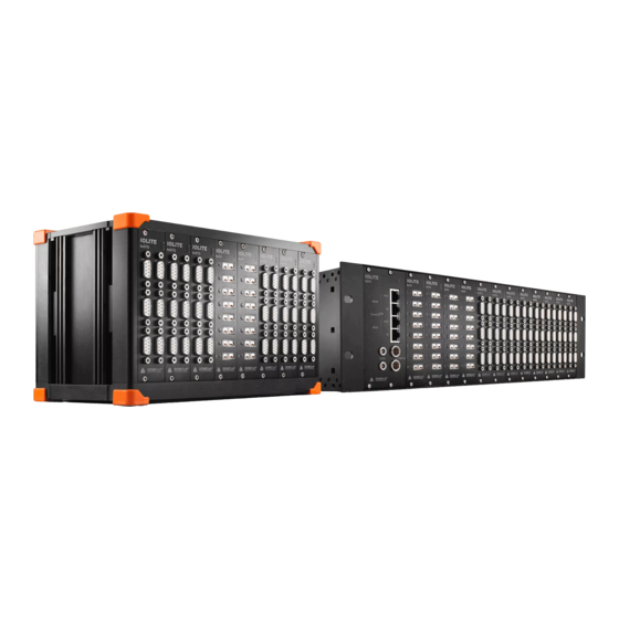
This is the Technical Reference Manual for IOLITE® Systems. IOLITE® is an industrial real time data acquisition hardware line that comes in many different form factors and can be equipped with a wide range of different amplifiers so that you can use it for virtually any measurement task. -
Page 8: Online Versions
The most recent version of this manual can be downloaded from our homepage: https://download.dewesoft.com/list/manuals-brochures/hardware-manuals In the Hardware Manuals section click the download link for the IOLITE® technical reference manual. 2.2.2. DewesoftX® User Manual The DewesoftX® User Manual document provides basics and additional information and examples for working with DewesoftX®... -
Page 9: Getting Started
TECHNICAL REFERENCE MANUAL 3. Getting started This chapter will help you to install the software, connect your IOLITE® system to the PC via EtherCAT® and will show you how to configure DewesoftX®. To follow these steps, you need the following items: your brand new Sirius system (included in the shipment) ●... -
Page 10: Connecting Iolite
First connect the power supply cable (PS-120-L1B2f) to the PWR IN 2-pin LEMO 1B male connector. Then connect a standard ethernet cable to the IN connector of BUS 1 on IOLITE-GATE. Finally connect the other side of the ethernet cable to the LAN port of PC. You can find advanced connections in chapter 3.3.1.4. - Page 11 IN connector. Finally connect the other side of the other side (RJ45) to the LAN port of the PC. You can find advanced connections in chapter 3.3.2.4. Connection of IOLITE. Connection of IOLITEi single-channel standalone device to PC IOLITE® V20-1 11/153...
-
Page 12: Dewesoftx® Settings Iolite
Settings item in the pop-up to open the DewesoftX® settings dialogue. DewesoftX® settings In the Devices section, you can see the connected IOLITE® slices. When you select one of them, the properties pane at the right will show the related data e.g. Serial number, Firmware version, etc. -
Page 13: Channel Setup Iolite
(or multiple channels) in the setup grid, the corresponding connectors in the image will be highlighted. The sampling rate will be set for all connected IOLITE® slices: of course only up to the max. sampling rate of the individual slices. - Page 14 IOLITE® TECHNICAL REFERENCE MANUAL Channel setup IOLITE-R8 IOLITE® V20-1 14/153...
-
Page 15: Simple Measurement
IOLITE® TECHNICAL REFERENCE MANUAL 3.3. Simple Measurement This chapter describes measurement basics, how to configure IOLITE® and gives some details on the measurement setup. 3.3.1. Help - Manual Note that this document is just a quick start guide. For detailed information about DewesoftX® consult ❶... -
Page 16: Analog Channel Setup
3.3.2. Analog channel setup In the analog channel setup screen you can see all channels of your connected IOLITE® systems. Per default only the first channel will be set to used. Unused channels will not show up in measure mode and can thus not be used for display, calculations or storing: thus, we will also set the other channels to ❶... -
Page 17: Sample Rate
One of the most important settings is the sample rate. The sample rate defines how many data points IOLITE® will transfer to DewesoftX®. A higher sample rate also means that more data needs to be transferred via EtherCAT® to your computer. -
Page 18: Measurement Mode
Now DewesoftX® has created a data file with all the data that you have seen during the recording session. You can now click the Analyse button (on the left-top of the screen to the right of the Measure button) to go to Analyse mode. IOLITE® V20-1 18/153... -
Page 19: Analyse Mode
Now you can use the cursors to analyse your data, zoom in and out of the data, click Offline math to add computations based on your data, etc. You can also change the design of your measurement displays, print reports based on your data and export the data to other file formats for further analysis. IOLITE® V20-1 19/153... -
Page 20: Advanced Configuration
IOLITE® TECHNICAL REFERENCE MANUAL 3.4. Advanced configuration Note, that the Dewesoft launcher has already done the hardware setup for you – you can check this in ❶ ❷ the Settings dialogue. Click the Options button – and then click the Settings menu item Open settings dialogue The settings window will appear where all the currently connected devices will be seen. -
Page 21: Firmware Upgrade
● the section Drivers. Copy the file into the Firmwares folder of your DewesoftX® installation (e.g. ● D:\DewesoftX\System\Firmwares). Connect the Dewesoft instrument to the PC and run DewesoftX®. ● Go to settings under the Update tab: ● Firmware update settings If the firmware package isn’t selected, select it by pressing the button and find the folder with... -
Page 22: Licensing
Active licenses tab All licenses regarding IOLITE® will only work when the IOLITE® system is connected to your PC and the device has been activated in the hardware setup. 3.7. Troubleshooting If your IOLITE®... -
Page 23: Additional Instructions For Troubleshooting With Ethercat Devices
TECHNICAL REFERENCE MANUAL 3.7.1. Additional instructions for troubleshooting with EtherCAT devices If the computer is still having trouble recognizing the Dewesoft EtherCAT devices, here are some additional steps: Check if there is an Ethercat DAQ Filter driver installed on your computer like shown on the ●... - Page 24 Go to network connections ○ Right-click on the connection where the EtherCAT devices are connected ○ Go to configure, advanced options, find Speed & Duplex, change the value to 100 Mbps ○ Full Duplex Ethernet advanced properties IOLITE® V20-1 24/153...
-
Page 25: System Overview
All-in-one solution for real-time control and feedback monitoring Voltage Strain / Stress Quarter Bridge Half Bridge Full Bridge Thermocouple Digital IO IEPE Charge Current LVDT TEDS Resistance EtherCAT IP40 -10 °C to +50 °C Compatible Compatible IOLITE® V20-1 25/153... -
Page 26: Main Features
IOLITE® TECHNICAL REFERENCE MANUAL 4.1. Main features DUAL ETHERCAT: IOLITE uses two EtherCAT buses in parallel. EtherCAT’s primary bus is used for ● full speed buffered data acquisition to a computer. The EtherCAT secondary bus is mainly used for real-time data to any 3rd party control system. -
Page 27: Input Slots And Amplifiers
IOLITE® TECHNICAL REFERENCE MANUAL 4.1.2. Input Slots and Amplifiers IOLITE chassis can be configured with up to 12 slots, each featuring high-quality input amplifiers. Currently, the following amplifiers are available: 6xSTG: universal analogue and strain gage ● amplifiers. Compatible with Dewesoft smart... -
Page 28: Redundant Power Supply
4.1.4. Feedback Monitoring What is really amazing is that IOLITE offers the operator to acquire and monitor the data in daily operation as well as while tuning the control systems. -
Page 29: System Specifications
Power Power supply Dual redundant 12 - 48 V DC Dual redundant 12 - 48 V DC Power consumption 9 W to 11 W (incl. IOLITE-GATE) 8 W (Max: 9 W) IOLITE-GATE: Max. 1.9 W Environmental Operating Temperature -10 to 50 °C -10 to 50 °C... - Page 30 Storage Temperature -20 to 60 °C Humidity 95 %, no condensation IP rating IP20 Physical Dimensions 82 mm x 62 mm x 52 mm (might differ for different modules) Weight 130 g (might differ for different modules) IOLITE® V20-1 30/153...
-
Page 31: Enclosure Overview
Standard IOLITE chassis is compatible and can be mounted in any 19-inch rack cabinet. This is perfect for the test-bed installations. IOLITE height is 4U and can host up to 12 IOLITE modules. It includes a cooling system with four fans on the back panel. -
Page 32: Iolite-R12: Cabinet Mount Chassis: Dimensions
IOLITE® TECHNICAL REFERENCE MANUAL Cooling system on the Back panel of IOLITE-R12 4.3.1.2. IOLITE-R12: Cabinet Mount Chassis: Dimensions Technical Drawings of IOLITE-R12 IOLITE® V20-1 32/153... -
Page 33: Iolite-Gate
Dewesoft EtherCAT devices or 3rd party control masters. It includes dual EtherCAT bus, redundant power supply inputs and provides synchronization with Dewesoft USB devices. IOLITE-GATE is mounted in the first slot from left inside the IOLITE-R12 19-inch rack cabinet chassis. IOLITE-GATE module IOLITE®... -
Page 34: Iolite-Gate: Connectors
TECHNICAL REFERENCE MANUAL 4.3.1.3.1. IOLITE-GATE: Connectors The IOLITE-GATE module includes 4x RJ45 connectors for dual EtherCAT bus. Primary bus (BUS 1) for buffered data and Secondary bus (BUS 2) for unbuffered data have IN and OUT connectors. Two 2-pin LEMO 1B connectors are used for redundant power supply (PWR IN). -
Page 35: Iolite-Gate: Power In: Pinout
USB devices for the same measurement. The signal that is transferred over sync cable makes sure that the measurement data of IOLITE and Dewesoft USB devices are perfectly synchronized to each other. The other use of a sync connector is to connect directly to IOLITE, a signal from the clock master. Hint There is no distinction between the IN and OUT –... -
Page 36: Iolite-Gate: Rj45: Pinout
The same connectors are used on Primary bus (BUS 1) for buffered data and on Secondary bus (BUS 2) for unbuffered data. Each RJ45 connector has two LEDs: GREEN LED indicates that IOLITE is connected to another device (Dewesoft EtherCAT device, PC or 3rd party control master). YELLOW LED is active only when the data transfer is active. -
Page 37: Iolite-Gate: Connection Of Iolite-R12 Standalone Device To Pc
To improve the redundancy of the system, it is recommended that the device is powered with two power supplies connected to different electrical fuses! Then connect a standard ethernet cable to the IN connector of BUS 1 on IOLITE-GATE. Finally, connect the other side of the ethernet cable to the LAN port of PC. -
Page 38: Iolite-Gate: Connection Of Iolite-R12 And Dewe-43A Device
USB cable to the USB port on PC. In order to have synchronized data between IOLITE and DEWE-43A, connect SYNC cable (e.g. L00B4m-L00B4m-0.2m) to the SYNC connector on IOLITE-GATE and the other side of cable to the SYNC connector on DEWE-43A. -
Page 39: Iolite-Gate: Connection Of Iolite-R12 Standalone Device To Iolite - Single Channel And Iolite - Multi Channel
RJ45-RJ45 cable to the IOLITE - single channel device. You need to connect the PS with the cable to the IOLITE POWER INJECTOR. Use the RJ45 to RJ45 cable again to connect the data line to IOLITE - multi channel device. The IOLITE - multi channel device will need an additional Power supply. -
Page 40: Iolite-R8: Boxed Chassis
TECHNICAL REFERENCE MANUAL 4.3.2. IOLITE-R8: Boxed Chassis In addition to 19-inch rack cabinet compatible chassis, IOLITE is also available in standalone aluminium chassis compatible with Sirius data acquisition instruments. The chassis provides 8 slots for IOLITE input and output slices to be installed. - Page 41 IOLITE® TECHNICAL REFERENCE MANUAL IOLITE-R8 Back panel IOLITE® V20-1 41/153...
-
Page 42: Iolite-R8: Boxed Chassis: Dimensions
IOLITE® TECHNICAL REFERENCE MANUAL 4.3.2.2. IOLITE-R8: Boxed Chassis: Dimensions Technical Drawings of IOLITE-R8 IOLITE® V20-1 42/153... -
Page 43: Iolite-R8: Boxed Chassis: Connectors
TECHNICAL REFERENCE MANUAL 4.3.2.3. IOLITE-R8: Boxed Chassis: Connectors The IOLITE-R8 chassis also enables dual EtherCAT bus. There are two 8-pin LEMO 1B connectors on the back panel of IOLITE-R8 used for data transfer and synchronisation on the primary bus (BUS 1) for buffered data. -
Page 44: Iolite-R8: Boxed Chassis: Sync: Pinout
USB devices for the same measurement. The signal that is transferred over sync cable makes sure that the measurement data of IOLITE and Dewesoft USB devices are perfectly synchronized to each other. The other use of a sync connector is to connect directly to IOLITE a signal from the clock master. Hint There is no distinction between the IN and OUT –... -
Page 45: Iolite-R8: Boxed Chassis: Bus 1: In: Pinout
IOLITE® TECHNICAL REFERENCE MANUAL 4.3.2.3.3. IOLITE-R8: Boxed Chassis: BUS 1: IN: Pinout IN connector of primary EtherCAT bus (BUS 1) is a 8-pin LEMO 1B male connector. Name Description TX_P Transmission + TX_N Transmission - RX_P Reception + RX_N Reception -... -
Page 46: Iolite-R8: Boxed Chassis: Bus 1: Out: Pinout
TECHNICAL REFERENCE MANUAL 4.3.2.3.4. IOLITE-R8: Boxed Chassis: BUS 1: OUT: Pinout The OUT connector of the primary EtherCAT bus (BUS 1) is a 8-pin LEMO 1B female connector. OUT connector enables power supply for external Dewesoft EtherCAT devices. Name Description... -
Page 47: Iolite-R8: Boxed Chassis: Bus 2: Rj45: Pinout
YELLOW LED is active only when the data transfer is active. Connector used on the device is a standard ethernet connector (RJ45). Standard ethernet cable with standard connector can be used to connect IOLITE-GATE with a PC. Name Description TX_P... -
Page 48: Iolite-R8: Boxed Chassis: Connection Of Iolite-R8 Standalone Device To Pc
Then connect L1T8f-RJ45-1M cable (LEMO side) to IN connector of BUS 1 on the IOLITE-R8 back panel. Finally, connect the other side of the L1T8f-RJ45-1M cable (RJ45 side) to the LAN port of the PC. -
Page 49: Iolite-R8: Boxed Chassis: Connection Of Iolite-R8 And Krypton® Device
2.3.2.4. Use EtherCAT to EtherCAT expansion cable (e.g. L1T8m-L1T8f-1M) and connect it to OUT connector on BUS 1 of IOLITE-R8 on one side and to IN connector of KRYPTON device on the other side. Connection of IOLITE-R8 and KRYPTON® device... -
Page 50: Iolite-R8: Boxed Chassis: Connection Of Iolite-R8 And Sirius® Device
Use power supply daisy chain cable (e.g. L1B2m-L1B2f-0.4m) to enable power supply for IOLITE-R8. Then connect L1T8f-RJ45-1M cable (LEMO side) to the IN connector of BUS 1 on the IOLITE-R8 back panel. Finally connect the other side of the L1T8f-RJ45-1M cable (RJ45 side) to the LAN port of PC. -
Page 51: Iolite-R8: Boxed Chassis: Connection Of Iolite Multi And Single Channel Device
Use the L1T8m-RJ-45 cable to connect the IOLITE - single channel device. An additional power cable is not needed, as the device can power over Ethernet cable. Use a RJ-45 - RJ-45 cable to connect the IOLITE - multichannel device. An additional Power supply is needed for the device with the cable. - Page 52 IOLITE® TECHNICAL REFERENCE MANUAL Function Dewesoft order code Power supply IOLITE-R8: PS-120-L1B2f (default) IOLITE-multichannel: EtherNET IOLITE-R8 to IOLITE single channel: RJ-45 - RJ-45 IOLITE single channel to IOLITE multi channel: RJ-45 - RJ-45 IOLITE® V20-1 52/153...
-
Page 53: Iolite - Multi Channel: Renders
Important For the power supply we have two TBLOCK connectors so the devices can be daisy chained with each other. 4.3.2.8. IOLITE - Multi channel: Renders IOLITE multi channel device *Old render- the new IOLITEi has two power connectors IOLITE® V20-1... -
Page 54: Iolite - Multi Channel: Connectors
IOLITE® TECHNICAL REFERENCE MANUAL 4.3.2.9. IOLITE - Multi channel: Dimension *Old dimensions - the new IOLITEi has two power connectors 4.3.2.10. IOLITE - Multi channel: Connectors 4.3.2.10.1. IOLITE - Multi channel: PWR IN IOLITE® V20-1 54/153... -
Page 55: Iolite - Multi Channel: Pwr Out
Connector (on the device): SL-SMT 5.08HC/02/90F 3.2SN BK BX Mating Connectors (for the cable): BLF 5.08HC/02/180 SN BK BX BLZP 5.08HC/02/180 SN BK BX 4.3.2.10.1. IOLITE - Multi channel: PWR OUT Name Description Supply Ground Power in connector: pin-out (2-pin male) Connector (on the device): SL-SMT 5.08HC/02/90F 3.2SN BK BX... -
Page 56: Ethernet Out
IOLITE® TECHNICAL REFERENCE MANUAL Standard ethernet cable with standard connector can be used to connect IOLITE - Multi channel to PC. Name Description TX_P Transmission + TX_N Transmission - RX_P Reception + RX_N Reception - EtherCAT connector: pin-out (RJ-45 female) 4.3.2.10.3. -
Page 57: Iolite: Single Channel Device
TECHNICAL REFERENCE MANUAL 4.3.3. IOLITE: Single channel device IOLITE single-channel modules are small and can be placed next to your measurement points. They offer screw holes for easy mounting with screws or any other method. Multiple IOLITE modules can be daisy-chained together with a single cost-effective Ethernet/EtherCAT cable with RJ45 connectors. -
Page 58: Iolite - Single Channel: Dimensions
4.3.3.3. IOLITE - Single channel: Connectors 4.3.3.3.1. EtherNET - IN (Data, Sync, PWR) Connector used on the device is a standard Ethernet connector (RJ45). Standard ethernet cable with standard connector can be used to connect IOLITE-Single channel with a Name Description... -
Page 59: Ethernet - Out (Data, Sync, Pwr)
IOLITE® TECHNICAL REFERENCE MANUAL 4.3.3.3.2. EtherNET - OUT (Data, Sync, PWR) Connector used on the device is a standard Ethernet connector (RJ45). Standard ethernet cable with standard connector can be used to connect IOLITE-Single channel with a Name Description TX_P... -
Page 60: Module Overview
Supports all High isolation, High isolation, High isolation, High isolation, High isolation functions strain types, strain types, high input high input high input support of high input low power range range range main TC types range consumption IOLITE® V20-1 60/153... - Page 61 Typ. 1.2 W, Typ. 1.2 W, Typ. 1.1 W, Max. 1.8 consumption per Max. 2.7 W Max. 1.9 W Max. 2.0 W module Advanced Pulsed excitation, Watchdog High sink current, Supercounter functions Cryogenic watchdog technology temperature range, High isolation IOLITE® V20-1 61/153...
- Page 62 82 x 62 x 28 mm 71 x 62 x 28 mm 71 x 62 x 28 mm 71 x 62 x 28 mm 82 x 62 x 28 mm Weight 130 g 130 g 130 g 130 g 130 g IOLITE® V20-1 62/153...
-
Page 63: Dio: Digital Input / Output Module
IOLITE® TECHNICAL REFERENCE MANUAL 5.1. DIO: Digital Input / Output Module IOLITE digital input / output modules are available in five different forms divided according to the number of digital inputs and outputs: 32 digital inputs ● 32 digital outputs ●... -
Page 64: Iolitei 32Xdo Module
IOLITE® TECHNICAL REFERENCE MANUAL 5.1.2. IOLITEi 32xDO Module IOLITEi-32xDO module IOLITE® V20-1 64/153... -
Page 65: Iolitei 8Xdi-4Xdo Module
IOLITE® TECHNICAL REFERENCE MANUAL 5.1.3. IOLITEi 8xDI-4xDO Module IOLITEi-8xDI-4xDO module IOLITE® V20-1 65/153... -
Page 66: Iolitei-4Xdo
Robust, isolated digital inputs are suitable for reading data off digital sensors as well as for demanding test automation tasks. Three power supply voltages (%V, 12V and device voltage supply level) available on the front connector. EtherCAT interface, signal and power over the same cable. IOLITEi-4xDI module IOLITE® V20-1 66/153... -
Page 67: Dio: Specifications
OMNIMATE SL 2.50 / BLF 2.50/180 Power supply 12 - 48 V DC Power out max. 2 A (unprotected) Power consumption Typ. 1.2 W, Max. 2.0 W Weight 230 g Slice Dimensions 128.4 x 115.4 x 30.1 mm IOLITE® V20-1 67/153... - Page 68 OMNIMATE SL 2.50 / BLF 2.50/180 Power supply 12 - 48 V DC Power out max. 2 A (unprotected) Power consumption Typ. 1.1 W, Max. 1.8 W Weight 184 g Slice Dimensions 128.4 x 115.4 x 30.1 mm IOLITE® V20-1 68/153...
- Page 69 +Vin pin Output Voltage +Vecat EtherCAT Bus Supply Voltage, 200 mA max. (see 1.) Power Power consumption 2.5 W Environmental IP rating IP20 Physical Dimensions 71 x 62 x 28mm Weight 130 g Rev: 1593518446 IOLITE® V20-1 69/153...
- Page 70 12 V +/-10 %, 100 mA max. Output Voltage +Vecat EtherCAT Bus Supply Voltage, 200 mA max. Power Power consumption 2.5 W Environmental IP rating IP20 Physical Dimensions 71 x 62 x 28 mm Weight 130 g Rev: 1593518446 IOLITE® V20-1 70/153...
-
Page 71: Dio: Connectors
/ output. 8 pins on a 9-pin connector bank are used for digital inputs and pin 9 for common GND. Additionally, there is a 2-pin terminal block connector with a 2.50 mm pitch for PWR OUT function. IOLITEi-32xDI front IOLITEi-8xDI-4xDO front IOLITEi-32xDO front IOLITE® V20-1 71/153... -
Page 72: Iolitei-32Xdi: Power Out: Pinout
Common ground DI connector (on the device): OMNIMATE Signal SL 2.50/09/90G Mating connector (for the cable): OMNIMATE Signal BLF 2.50/09/180 Important The common ground is not shared through all the 32 channels, but by groups of 8 channels. IOLITE® V20-1 72/153... -
Page 73: Iolitei-32Xdo: Digital Output: Pinout
DO 7 Digital output 7 DO 8 Digital output 8 Digital out connector: pin-out (terminal block male) Common ground DO connector (on the device): OMNIMATE Signal SL 2.50/09/90G Mating connector (for the cable): OMNIMATE Signal BLF 2.50/09/180 IOLITE® V20-1 73/153... -
Page 74: Iolitei-8Xdi-4Xdo: Power Out: Pinout
+ PWR IN DI Input voltage - PWR IN DI Input ground Power in connector: pin-out (terminal block male) PWR OUT connector (on the device): OMNIMATE Signal SL 2.50/02/90G Mating connector (for the cable): OMNIMATE Signal BLF 2.50/02/180 IOLITE® V20-1 74/153... -
Page 75: Iolitei-8Xdi-4Xdo: Digital Input: Pinout
+ PWR IN DO Input voltage - PWR IN DO Output ground Power in connector: pin-out (terminal block male) PWR OUT connector (on the device): OMNIMATE Signal SL 2.50/02/90G Mating connector (for the cable): OMNIMATE Signal BLF 2.50/02/180 IOLITE® V20-1 75/153... -
Page 76: Iolitei-8Xdi-4Xdo: Digital Output: Pinout
Digital output 3 Output ground DO 4 Digital output 4 Output ground Digital out connector: pin-out (terminal block male) DO connector (on the device): OMNIMATE Signal SL 2.50/09/90G Mating connector (for the cable): OMNIMATE Signal BLF 2.50/09/180 IOLITE® V20-1 76/153... -
Page 77: Iolitei-4Xdo And 4Xdi Connectors: Pinout
5 V supply, max. 300 mA 5 V supply, max. 300 mA +12V/130mA +12V/130mA 12 V supply, max.130 mA 12 V supply, max.130 mA Ground Ground Ground Ground /200mA Supply voltage, max. 200 mA /200mA Supply voltage, max. 200 mA supply supply IOLITE® V20-1 77/153... -
Page 78: Low Voltage Module
BNC or terminal block connectors and a range of either 10 or 100 V. On the other hand, the 16-channel version only comes with channel-to-ground isolation in the form of terminal block connectors, but a higher range of 200 V. IOLITEi-8xLV IOLITE® V20-1 78/153... -
Page 79: Iolite-16Xlv
IOLITE® TECHNICAL REFERENCE MANUAL 5.2.2. IOLITE-16xLV IOLITE-16xLV-TBLOCK modules have TBLOCK connectors for analog input. IOLITE-16xLV-TBLOCK module IOLITE® V20-1 79/153... -
Page 80: Specifications
1000 Vpeak channel to ground & channel to channel Power Consumption Typ. 2.4 W, Max. 3.5 W Input Connectors Terminal block 2 pole OMNIMATE SL 2.50 / BLF 2.50/180 Slice Dimensions 128.4 x 127.6 x 30.1 mm 128.4 x 115.4 x 30.1 mm IOLITE® V20-1 80/153... - Page 81 Isolation Voltage (channel to power supply ground) Power Consumption Typ. 3.4 W (Max. 4.2 W) Terminal block 9 pole Input Connectors OMNIMATE SL 2.50 / BLF 2.50/180 Slice Dimensions 128.4 x 115.4 x 30.1 mm Rev: 1614067200 IOLITE® V20-1 81/153...
-
Page 82: Connectors
IOLITE® TECHNICAL REFERENCE MANUAL 5.2.4. LV: Connectors 5.2.4.1. IOLITEi-8xLV: BNC Connector IOLITE LV module has 8 BNC connectors for analog input. IOLITEi-8xLV-10V front IOLITEi-8xLV front IOLITE® V20-1 82/153... -
Page 83: Iolitei-8Xlv: Bnc Connector: Pin Out
IOLITE® TECHNICAL REFERENCE MANUAL 5.2.4.2. IOLITEi-8xLV: BNC Connector: Pin out Name Description Analog input Ground LV connector: pin-out (BNC) 5.2.4.3. LV: BNC Connector: Wiring diagram 5.2.4.3.1. LV: Voltage IOLITE® V20-1 83/153... -
Page 84: Iolitei-8Xlv: Tblock Connector
IOLITE® TECHNICAL REFERENCE MANUAL 5.2.4.4. IOLITEi-8xLV: TBLOCK Connector IOLITEi-8xLV-TBLOCK and IOLITEi-8xLV-10V-TBLOCK modules have 8 TBLOCK connectors for analog input. IOLITEi-8xLV-TBLOCK front IOLITEi-8xLV-10V-TBLOCK front IOLITE® V20-1 84/153... -
Page 85: Iolitei-8Xlv: Tblock Connector: Pin Out
Analog input - LV connector: pin-out (TBLOCK male) Connector (on the device): OMNIMATE Signal SL 2.50/02/180G 3.2SN BK BX Mating connector (for the cable): OMNIMATE Signal BLF 2.50/02/180 5.2.4.6. 8xLV: TBLOCK Connector: Wiring diagram 5.2.4.6.1. 8xLV: Voltage IOLITE® V20-1 85/153... -
Page 86: Iolite-16Xlv Connectors
IOLITE® TECHNICAL REFERENCE MANUAL 5.2.4.7. IOLITE-16xLV Connectors IOLITE-16xLV TBLOCK modules have 4 TBLOCK connectors for analog input. IOLITEi-16xLV-TBLOCK front 5.2.4.8. IOLITE-16xLV: TBLOCK Power Connector: Pinout Name Description Analog input + Analog input - LV connector: pin-out (TBLOCK male) Connector (on the device): OMNIMATE Signal SL 2.50/02/90G Mating connector (for the cable): OMNIMATE Signal BLF 2.50/02/180... -
Page 87: Iolite-16Xlv: Analog Input: Pinout
IOLITE® TECHNICAL REFERENCE MANUAL 5.2.4.9. IOLITE-16xLV: Analog input: Pinout Name Description AI 1 + Analog input 1 AI 1 - Input ground 1 AI 2 + Analog input 2 AI 2 - Input ground 2 AI 3 + Analog input 3... -
Page 88: 16Xlv: Tblock Connector: Wiring Diagram
IOLITE® TECHNICAL REFERENCE MANUAL 5.2.4.10. 16xLV: TBLOCK Connector: Wiring diagram 5.2.4.10.1. 16xLV: Voltage IOLITE® V20-1 88/153... -
Page 89: La: Low Amperage
The IOLITEi-8xLA is a multi channel low current measurement module. It is a perfect device for data acquisition in control applications requiring an input current range of ±20 mA. It features channel to channel isolation and comes with either BNC or terminal block connectors. IOLITEi-8xLA modules IOLITE® V20-1 89/153... -
Page 90: La: Specifications
1000 Vpeak channel to ground & channel to channel Power Consumption Typ. 2.8 W, Max. 3.5 W Terminal block 2 pole Input Connectors OMNIMATE SL 2.50 / BLF 2.50/180 Slice Dimensions 128.4 x 127.6 x 30.1 mm 128.4 x 115.4 x 30.1 mm Rev: 1614067200 IOLITE® V20-1 90/153... -
Page 91: La: Bnc Connector
IOLITE® TECHNICAL REFERENCE MANUAL 5.3.2. LA: BNC Connector IOLITE-8xLA-BNC module 5.3.2.1. 8xLA: BNC Connector: Pinout Name Description Analog input Ground LV connector: pin-out (BNC) IOLITE® V20-1 91/153... -
Page 92: 8Xla: Bnc Connector: Wiring Diagram
IOLITE® TECHNICAL REFERENCE MANUAL 5.3.2.2. 8xLA: BNC Connector: Wiring diagram 5.3.2.2.1. 8xLA: Current IOLITE® V20-1 92/153... -
Page 93: La: T2A2F Connector
IOLITE® TECHNICAL REFERENCE MANUAL 5.3.3. LA: T2A2f Connector IOLITE-8xLA-T2A2f module 5.3.3.1. 8xLA: TBLOCK Connector: Pinout Name Description Analog input + Analog input - LA connector: pin-out (TBLOCK male) Connector (on the device): OMNIMATE Signal SL 2.50/02/180G 3.2SN BK BX Mating connector (for the cable): OMNIMATE Signal BLF 2.50/02/180 IOLITE®... -
Page 94: 8Xla: Tblock Connector: Wiring Diagram
IOLITE® TECHNICAL REFERENCE MANUAL 5.3.3.2. 8xLA: TBLOCK Connector: Wiring diagram 5.3.3.2.1. 8xLA: Current IOLITE® V20-1 94/153... -
Page 95: Rtd: Resistance Temperature Detector Module
5.4. RTD: Resistance Temperature Detector Module IOLITEi RTD module with 6-pin LEMO 0B input connectors is used for measurements with universal platinum thermometer probes, thermistors, as well as for resistance and voltage measurements. IOLITEi-8xRTD module has 8 isolated measurement channels. IOLITEi-8xRTD module IOLITE® V20-1 95/153... -
Page 96: Rtd: Specifications
LEMO 0B 6pin EEA.0B.306.CLN, Terminal Block Weidmueller SL 2.50-04 Isolation voltage 1000 Vpeak channel to ground & channel to channel Power supply 12 - 48 V DC Power consumption Typ. 2.1 W, Max. 2.7 W Weight 260 g Dimensions 128.4 x 115.4 x 30.1 mm IOLITE® V20-1 96/153... - Page 97 Lemo 0B 6pin EEA.0B.306.CLN Isolation voltage 1000 Vpeak channel to ground & channel to channel Power supply 12 - 48 V DC Power consumption Typ. 2.1 W, Max. 2.7 W Weight 260 g Dimensions 128.4 x 115.4 x 30.1 mm IOLITE® V20-1 97/153...
-
Page 98: Rtd: Lemo L0B6F Connector
IOLITE® TECHNICAL REFERENCE MANUAL 5.4.2. RTD: LEMO L0B6f Connector IOLITEi-8xRTD and IOLITEi-8xRTDp module have eight 6-pin LEMO 0B female connectors. IOLITEi-8xRTD front IOLITE® V20-1 98/153... -
Page 99: Rtd: Lemo L0B6F Connector: Pinout
Do not connect Exc+ Excitation+ Exc- Excitation- RTD connector: pin-out (6-pin LEMO female) Do not connect RTD connector (on the device): EEA.0B.306.CLN Mating connector (for the cable): FGA.0B.306.CLAD21Z 5.4.2.2. RTD: LEMO L0B6f Connector: Wiring diagram 5.4.2.2.1. RTD: Voltage IOLITE® V20-1 99/153... -
Page 100: Rtd: Resistance
IOLITE® TECHNICAL REFERENCE MANUAL 5.4.2.2.2. RTD: Resistance 3-wire 4-wire 5.4.2.2.3. RTD: Temperature 3-wire 4-wire IOLITE® V20-1 100/153... -
Page 101: Rtd-Tblock: Terminal Block Connector
IOLITE® TECHNICAL REFERENCE MANUAL 5.4.3. RTD-TBLOCK: Terminal block connector IOLITEi-8xRTD-TBLOCK module has 8 terminal block Weidmueller SL 2.50-04 female connectors. IOLITEi-8xRTD-TBLOCK front IOLITE® V20-1 101/153... -
Page 102: Rtd-Tblock: Terminal Block Connector: Pinout
IOLITE® TECHNICAL REFERENCE MANUAL 5.4.3.1. RTD-TBLOCK: Terminal block connector: Pinout Name Description Input- Input+ Exc- Excitation- Exc+ Excitation+ RTD connector: pin-out (TBLOCK male) IOLITE® V20-1 102/153... -
Page 103: Stg: Strain Gauge Module
IOLITEi 1xSTG single channel slice 5.5.1. IOLITE-6xSTG IOLITE 6xSTG modules have universal 6 channel differential voltage, current and Full / Half / Quarter bridge input with DSUB-9 connector. Compatible with DSI adapters for IEPE, CHG, 200 V, RTD, TH measurements. -
Page 104: Iolitei-1Xstg Module
IOLITE® TECHNICAL REFERENCE MANUAL 5.5.3. IOLITEi-1xSTG module 5.5.4. STG: Specifications IOLITE 6xSTG Analog inputs - Voltage Input type Voltage Full / half / quarter bridge strain Current Potentiometer Number of channels ADC Type 24-bit SAR with anti-aliasing filter Sampling Rate... - Page 105 5.4 W, Max. 11.1 W (7.9 W 120 Ω @ 5 V load, 8.8 W 350 Ω @ 10 V load) Weight 340 g Slice Dimensions 128.4 x 115.4 x 30.1 mm IOLITEi 1xSTG Analog input - Voltage Voltage, current, full bridge strain, half bridge strain, quarter bridge Input types strain Number of channels IOLITE® V20-1 105/153...
- Page 106 Protection Continuous short to ground Bridge Connection Types full bridge strain, ½ bridge strain, ¼ bridge strain (3 wire) Bridge ranges 20…10000 mV/V free programmable Internal Bridge Completion ½ bridge and ¼ bridge 120 and 350 Ω IOLITE® V20-1 106/153...
- Page 107 Shunt Resistor Accuracy 0.1 %; TCR: 10 ppm/K (others on request) Input Short, Sensor Offset Adjust Software-selectable Power Power consumption 2.5 W Environmental IP rating IP20 Physical Dimensions 71 x 62 x 28 mm Weight 130 g Rev: 1593518446 IOLITE® V20-1 107/153...
-
Page 108: Stg: Dsub-9 Connector
IOLITE® TECHNICAL REFERENCE MANUAL 5.5.5. STG: DSUB-9 Connector IOLITE-6xSTG module has 6 standard DSUB-9 female connectors for voltage or strain measurement. IOLITE-6xSTG front 5.5.5.1. DSUB-9 Connector: Pinout Name Description Exc+ Excitation+ Input+ Sns- Sense- Ground ¼ Bridge / Shunt Sns+... -
Page 109: Stg: Dsub-9 Connector: Wiring Diagram
IOLITE® TECHNICAL REFERENCE MANUAL 5.5.5.2. STG: DSUB-9 Connector: Wiring diagram 5.5.5.2.1. STG: Voltage Single ended Differential Use only when sensor Output (+) and Output (-) are referenced to Gnd. Gnd must be connected. 5.5.5.2.2. STG: Potentiometer IOLITE® V20-1 109/153... -
Page 110: Stg: Bridge
IOLITE® TECHNICAL REFERENCE MANUAL 5.5.5.2.3. STG: Bridge Full bridge Half bridge Quarter bridge IOLITE® V20-1 110/153... -
Page 111: Stg: Current
IOLITE® TECHNICAL REFERENCE MANUAL 5.5.5.2.4. STG: Current External direct shunt External loop powered shunt Internal shunt IOLITE® V20-1 111/153... -
Page 112: Stg: Resistance
IOLITE® TECHNICAL REFERENCE MANUAL 5.5.5.2.5. STG: Resistance IOLITE® V20-1 112/153... -
Page 113: Stgs: Strain Gauge Module
STGS is a dedicated module for strain measurement with a new ADC - 24-bit delta-sigma with anti-aliasing filter. The module can be found in the following options: 6xSTGS as a slot slice 6xSTGS as a standalone module IOLITE-8: STGS module IOLITE® V20-1 113/153... -
Page 114: Stgs: Specifications
Internal Shunt Resistor 100 kΩ software selecteable to SNS+ or SNS- and In+ or In- Shunt Resistor Accuracy 0.05 %; TCR: 10 ppm/K (others on request) Input Short, Sensor Offset Adjust Software-selectable Additional Specifications Input connectors Terminal block, D-SUB37, D-SUB9 Micro-D IOLITE® V20-1 114/153... -
Page 115: Stgs: Connectors
TEDS support Available for Terminal block, D-SUB9 Micro-D Power supply 9 - 48 V DC Power Consumption Typ. 2.7 W, Max. 5.1 W (120 Ω @ 5 V load) 5.6.2. STGS: Connectors 5.6.2.1. STGS: D-SUB37 Connector: Pinout IOLITE® V20-1 115/153... -
Page 116: Stgs: Wiring Diagram
IOLITE® TECHNICAL REFERENCE MANUAL 5.6.2.2. STGS: Wiring diagram 5.6.2.2.1. STGS: D-SUB37: Voltage Single ended Differential 5.6.2.2.2. STGS: D-SUB37: Potentiometer IOLITE® V20-1 116/153... -
Page 117: Stgs: D-Sub37: Bridge
Quarter bridge 5.7. TH: Thermocouple Module IOLITE TH modules are isolated DAQ devices for temperature measurements using thermocouples. Isolated thermocouple modules can acquire data from any kind of thermocouple (K, J, T, R, S, N, E, C, B). It offers sensor break detection in software as well as using LED indicators. -
Page 118: Th: Specifications
Accuracy ±0.02 % of reading ±0.5 °C ±10 μV Resolution < 0.001 °C Sampling rates 10, 20, 40, 80, 100 S/sec Typical Noise 0.007 °C RMS@Type K @ 10 S/sec 0.02 °C RMS@Type K @ 100 S/sec IOLITE® V20-1 118/153... - Page 119 Mini Thermocouple connector (copper) Isolation voltage 1000 Vpeak channel to ground & channel to channel Power supply 12 - 48 V DC Power consumption 3.2 W Weight 230 g Slice Dimensions 128.4 x 115.4 x 30.1 mm IOLITE® V20-1 119/153...
-
Page 120: Th: Miniature Thermocouple Connector
IOLITE® TECHNICAL REFERENCE MANUAL 5.7.2. TH: Miniature Thermocouple Connector IOLITEi-8xTH module has 8 miniature thermocouple-connectors for temperature measurement. IOLITEi-8xTH front 5.7.2.1. TH: Miniature Thermocouple Connector: Pinout Name Description Input+ Input- TH connector: pin-out (Mini TC female) IOLITE® V20-1 120/153... -
Page 121: Th: Miniature Thermocouple Connector: Wiring Diagram
IOLITE® TECHNICAL REFERENCE MANUAL 5.7.2.2. TH: Miniature Thermocouple Connector: Wiring diagram 5.7.2.2.1. TH: Voltage 5.7.2.2.2. TH: Temperature T-type thermocouple S-type, R-type thermocouple IOLITE® V20-1 121/153... - Page 122 IOLITE® TECHNICAL REFERENCE MANUAL N-type thermocouple K-type thermocouple J-type thermocouple E-type thermocouple B-type thermocouple C-type thermocouple IOLITE® V20-1 122/153...
-
Page 123: Cnt: Counter Module
IOLITE® TECHNICAL REFERENCE MANUAL 5.8. CNT: Counter Module IOLITE CNT has 4 channels, each capable of 3x digital inputs, 1x event counter, encoder, period, pulse-width, duty-cycle, and precise frequency and angle measurement using patented SUPERCOUNTER® technology. IOLITE-4xCNT Module IOLITE® V20-1... -
Page 124: Cnt: Specifications
Additional Specifications Input connector 7-pin LEMO 1B series EEG.1B.307.CLNY Preliminary: Terminal block OMNIMATE Signal SL Series SL 2.50/09/90G Power supply 12 - 48 V DC Slice Dimensions 128.4 x 115.4 x 30.1 mm IOLITE® V20-1 124/153... -
Page 125: Cnt: Lemo L1B7F Connector
IOLITE® TECHNICAL REFERENCE MANUAL 5.8.2. CNT: LEMO L1B7f Connector IOLITE-4xCNT module has four 7-pin LEMO connectors for digital, counter and encoder inputs. IOLITE-4xCNT Front IOLITE® V20-1 125/153... -
Page 126: Cnt: Lemo L1B7F Connector: Pinout
+12V 12 V supply Ground Connector on the module: EGG.1B.307.CLL Mating cable connector: FGG.1B.307.CLAD52 5.9. AO: Analog output module The IOLITE AO module comes in the following options: 16xAO slot slice ● 16xAO single slice ● 1xAO single channel device ●... -
Page 127: Iolite 16Xao
IOLITE® TECHNICAL REFERENCE MANUAL 5.9.1. IOLITE 16xAO IOLITE-16xAO Module 5.9.2. IOLITE-1xAO Low-latency, high precision analog output with excellent dynamic performance. Under 100 microseconds of etherCAT-to-analog delay possible(on a real-time EtherCAT controller). IOLITE-1xAO Front IOLITE® V20-1 127/153... -
Page 128: Ao: Specifications
Typ. 4.3 W, Max. 7.2 W Weight 210 g Slice Dimensions 128.4 x 115.4 x 30.1 mm Rev: 1603360800 1) Only asynchronous mode is supported in Dewesoft, function generator is not supported 2) Only DC output voltage, function generator not supported IOLITE® V20-1 128/153... - Page 129 IP rating IP20 Physical Dimensions 82 x 62 x 28 mm Weight 130 g 1) Only asynchronous mode is supported in Dewesoft, function generator is not supported 2) Only DC output voltage, function generator not supported Rev: 1593518446 IOLITE® V20-1 129/153...
-
Page 130: Iolite 16Xao: Terminal Block Connectors
IOLITE® TECHNICAL REFERENCE MANUAL 5.9.4. IOLITE 16xAO: Terminal block Connectors IOLITE-16xAO Front 5.9.4.1. IOLITE-16xAO: TBLOCK Power Connector: Pinout Name Description Analog input + Analog input - LV connector: pin-out (TBLOCK male) Connector (on the device): OMNIMATE Signal SL 2.50/02/90G Mating connector (for the cable): OMNIMATE Signal BLF 2.50/02/180 IOLITE®... -
Page 131: Iolite-16Xao Terminal Block Connector: Pinout
IOLITE® TECHNICAL REFERENCE MANUAL 5.9.4.2. IOLITE-16xAO Terminal block connector: Pinout Name Description AO 1 Analog out 1 iGND Ground AO 2 Analog out 2 iGND Ground AO 3 Analog out 3 iGND Ground AO 4 Analog out 4 AO connector: pin-out (TBLOCK male) -
Page 132: Acc: Accelerometer
0.3 μV/K + 5 ppm of range/K (max. 2 µV/K + 10 ppm of range/K) Gain Linearity < 0.02 % Input Coupling DC, AC 0.1 Hz, 1 Hz Input Impedance 1 MΩ Overvoltage Protection In+ to In-: 50 V continuous, 200 V peak (10 msec) IOLITE® V20-1 132/153... -
Page 133: Acc: Bnc Connector
Power consumption Environmental IP rating IP20 Physical Dimensions 82 x 62 x 28 mm Weight 130 g Rev: 1593518446 5.10.2. ACC: BNC Connector 5.10.2.1. ACC: BNC Connector: Pinout Name Description Input + Ground ACC connector: pin-out (BNC) IOLITE® V20-1 133/153... -
Page 134: Acc: Bnc Connector: Wiring Diagram
IOLITE® TECHNICAL REFERENCE MANUAL 5.10.2.2. ACC: BNC Connector: Wiring diagram 5.10.2.2.1. ACC: Voltage 5.10.2.2.2. ACC: IEPE IOLITE® V20-1 134/153... -
Page 135: Iolite-3Xmems-Acc
Windows PC, or alternatively to any controller running EtherCAT master on any platform. Scaling is automatic in DEWESoft software, therefore the data in g or m/s2 is readily available to the user. MEMS sensor internal temperature is also available as a data channel in DEWESoft software under System monitor channels. -
Page 136: 3Xmems-Acc: Specifications
0.1 % FS 0.1 % FS Crossaxis sensitivity -1 % MEMS Inclinometer Accuracy and resolution valid in range +-15 deg Accuracy and resolution valid for bandwidth < 0.1 deg Relative accuracy (23 degC) 0.01 deg Resolution 0.001 deg IOLITE® V20-1 136/153... -
Page 137: Ecat Accessories
6. ECAT Accessories 6.1. IOLITE Power injector IOLITE Power Injector is a passive PoE power injector. It merges a 12-48V DC power source and the EtherCAT communication into a single CAT6 cable. The IOLITE single channel devices need the IOLITE Power injector as the first device in the chain. -
Page 138: Iolite Power Injector: Connector
IOLITE® TECHNICAL REFERENCE MANUAL 6.1.2. IOLITE Power Injector: Connector 6.1.2.1. IOLITE Power Injector: 2 mm Jack Pinout Name Description Supply Ground For the power supply an unregulated DC voltage between 12 V and 48 V is required. Power in connector: pin-out (2 mm DC jack, male) Connector (on the device): 2 mm DC power jack - PJ-067A 6.1.2.2. -
Page 139: Iolite Repeater
Daisy-chains and increases the distance for signal, synchronization and power between IOLITEi single channel instruments. Suggested length of the cable is up to 50 m. 6.2.1. General specifications General specifications of the IOLITE Repeater device Digital interface EtherCAT EtherCAT connector... -
Page 140: Connectors
IOLITE® TECHNICAL REFERENCE MANUAL 6.2.2. Connectors Connector used on the device is a standard ethernet connector (RJ45). Standard ethernet cable with standard connector can be used to connect IOLITE-RPT with a device. 6.2.2.1. EtherNET - IN Name Description TX_P Transmission +... -
Page 141: Accessories
Optional Accessories and Sensors (e.g. DSI®-adapters, Battery Packs, Current Clamps, etc.) can be found in a separate document, which is available for download from our homepage: https://download.dewesoft.com/download-file/accessories-and-sensors-technical-reference-manual.pdf In the HW Manuals section click the download link for the Manual for DewesoftX® Accessories and Sensors. IOLITE® V20-1 141/153... -
Page 142: Appendix
If we use a baud rate of 2400 and a phase modulation (which can transmit four bits per baud), this means that we can transfer 9600 bit/s. 2400 baud x 4 bits per baud = 9600 bps. The baud rate (communication speed) between the DS GATE and the measurement modules can be configured via software. IOLITE® V20-1 142/153... - Page 143 A ratio in decibels is ten times the logarithm to base 10 of the ratio of two power quantities. Dewesoft Dewesoft refers to the company. DewesoftX® refers to the software suite for data acquisition, data processing, data analysis and much more.
- Page 144 LEMO is the name of the high quality push-pull connectors that are used for cable connections: e.g. the power-supply cable and the sync cables of the Sirius® system. The company that produces these www.lemo.com connectors is also called LEMO ( IOLITE® V20-1 144/153...
- Page 145 PC where DewesoftX® is installed. NET Option aka. Dewesoft’s NET, DEWE NET With DEWE-NET your measurement system can be controlled remotely with ease of use you couldn't imagine before. DEWE-NET also serves as the center of Distributed Data Acquisition systems where you have multiple systems located either together or scattered across an entire continent.
- Page 146 (usually PCs). Sirius® systems use a USB connection to connect to a PC. Windows® A PC operating system by Microsoft®. DewesoftX® will work on Windows® XP, Windows® Vista and Windows® Windows® is a registered trademark of Microsoft Corporation in the United States and other countries. IOLITE® V20-1 146/153...
-
Page 147: Warranty Information
9.2. Support Dewesoft has a team of people ready to assist you if you have any questions or any technical difficulties regarding the system. For any support please contact your local distributor first or Dewesoft directly. -
Page 148: Copyright
When used in text representing the company, product or technology name, the ® sign is not used. The Dewesoft triangle logo is a registered trademark but the ® sign is not used in the visual representation of the triangle logo. -
Page 149: Safety Instructions
Dewesoft GmbH assumes no liability for the customer’s failure to comply with these requirements. All accessories shown in this document are available as an option and will not be shipped as standard parts. -
Page 150: System And Components Recycling
This symbol indicates that this system complies with the European Union’s requirements according to Directive 2002/96/EC on waste electrical and electronic equipment (WEEE). Please find further information about recycling on the Dewesoft web site www.dewesoft.com Restriction of Hazardous Substances This product has been classified as Monitoring and Control equipment and is outside the scope of the... - Page 151 REMOVE POWER and do not use the product until the safe operation can be verified by service-trained personnel. If necessary, return the product to the Dewesoft sales and service office for service and repair to ensure that safety features are maintained.
- Page 152 Devices and systems according to IEC 61508 or IEC 61511 which are considered as “operationally well-tried”, are excluded from the scope of IEC 61326-3-1. Fire-alarm and safety-alarm systems, intended for the protection of buildings, are excluded from the scope of IEC 61326-3-1. IOLITE® V20-1 152/153...
-
Page 153: Documentation Version History
1.0.0 10.11.2019 Initial version ● V20-1 14.07.2020 Added devices: ● LV modules (IOLITEi-8xLV, IOLITEi-8xLV-10V, ○ IOLITEi-8xLV-TBLOCK, IOLITEi-8xLV-10V-TBLOCK) DIO module (IOLITEi-8xDI-4xDO) ○ RTD module (IOLITE-RTD-TBLOCK) ○ CNT module (IOLITE-4xCNT) ○ Updated template ● V21-1 25.2.21 Added devices: ● 16xLV ○ 8xLA ○...
Need help?
Do you have a question about the IOLITE and is the answer not in the manual?
Questions and answers