Table of Contents
Advertisement
Quick Links
Advertisement
Table of Contents

Related Manuals for FONESTAR PDA-207


Summary of Contents for FONESTAR PDA-207
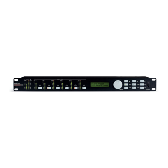
- Page 1 PD -207 LOUDSPEAKER PROCESSOR 2 INPUTS AND 6 OUTPUTS INSTRUCTION MANUAL...
- Page 2 We take this opportunity to thank you for buying this product. We recommend you read the instruction manual before switching on the machine and follow the instructions that are given. Keep the manual for future reference. SECURITY AND THE ENVIRONMENT ELECTRICAL SECURITY Check that the current in the mains connection where the machine is to be installed corresponds to the power supply of the machine.
-
Page 3: Exemption Of Liability
The characteristics of the equipment and the content of the manual can change without forewarning. FONESTAR, S.A. does not assume responsibilities regarding the inappropriate use of the equipment or the information supplied in this instruction manual, and specifically disclaims any implied liability for marketability or fitness for any other use. -
Page 4: Controls And Functions Front Panel
DESCRIPTION Loudspeaker processor with 2 inputs and 6 outputs designed to process and adapt the audio signal to the characteristics of the PA system loudspeakers offering an independent signal in each output. It incorporates equalization, frequency divider, gain control, limiter, delay and mute functions. CONTROLS AND FUNCTIONS FRONT PANEL 1.- Input level meters and CLIP: LED indicators for the signal level in inputs A and B. -
Page 5: Rear Panel
REAR PANEL 1.- AC INPUT: to connect the AC power supply cable. 2.- AES/EBU DIGITAL INPUT: AES/EBU digital type input, XLR connector. 3.- ETHERNET: computer connection port, RJ-45 connector. 4.- OUTPUTS 1-6: channel output connectors, XLR connector. 5.- INPUTS A-B: channel A and B input connectors, XLR connector. INSTRUCTIONS FOR USE GENERAL INFORMATION When you switch the equipment on, the current configuration is shown on the display:... -
Page 6: Input Configuration
INPUT CONFIGURATION The different input process functions can be set: GAIN, EQ, DELAY. To access the configuration menus press the IN button and choose the different process functions with the (a, d) selection buttons. GAIN It allows the signal level in each input to be individually adjusted. Note: as the gain is adjusted digitally, the user can select the required input level, but must be careful not to select too high a volume and saturate the signal. - Page 7 - Filter types (PEAK, LOW SH, HIGH SH). To select the filter type to be applied: Peaking Low shelving High shelving - Bypass. It allows the chosen filter to be deactivated. Central frequency/ cutoff frequency (Hz). It allows the central frequency of the peaking filter or the cut off frequency of the high or low pass filters to be chosen.
-
Page 8: Output Configuration
- DELAY. It allows a delay to be applied to the input. To set the delay, follow the instructions below: - Press the IN button and using the (a, d) selection buttons, choose the DELAY option on the menu (INA Delay or INB Delay will appear on the display). - Page 9 HPF & LPF A high pass filter and low pass filter is allowed in each output. Each output has two displays, one for each filter, where the output number and filter type appear. To set the low and high pass filters, follow the instructions below: - Press the OUT button and using the (a, d) selection buttons, choose the LPF or HPF option from the menu (OPx HPF or OPx LPF will appear on the display).
- Page 10 POLARITY It allows the output signal phase to be individually reversed. To set the output signal phase, follow the instructions below: - Press the OUT button and using the (a, d) selection buttons, choose the POLARITY option on the menu (OPx Polarity will appear on the display).
- Page 11 The configuration parameters are saved in a memory bank so that they can be later reused. When the processor is switched on, the last configuration used before the processor was switched off is loaded. LOAD PRESET The processor loads the last configuration used by default and shows it on the display. To load another setting, follow the instructions below: - Press the LOAD button.
- Page 12 - Output meters: To choose whether the point that the output level indicator signal is taken from is before or after the MUTE button. To set the point that the output level indicator signal is taken from, follow the instructions below: - Press the UTIL button and use the (a, d) selection buttons to choose the MISC SETUP option from the menu.
- Page 13 - UART ID number: Shows the number of the system connected to the installation. LOCK SUBMENU This allows the equipment to be protected against accidental or unauthorized changes. There are different types of protection: Total: all the editing functions and access to configurations are disabled. By user setting: users lock the configuration of their choice.
- Page 14 CONNECTION The digital processor PDA-207 accepts multiple configurations. 2 connection examples are described below: 4-WAY MONO SYSTEM + 2 MONITORS Input A to outputs 1, 2, 3 and 4 with independent equalization (A1234). The mix of inputs A and B to outputs 5 and 6 (S56).
- Page 15 3 -WAY STEREO SYSTEM (2 X 3 WAYS) Input A to outputs 1, 3 and 5 with independent equalization (A135). Input B to outputs 2, 4 and 6 with independent equalization (B246). - 15 -...
- Page 16 SOFTWARE The PDA-207 digital processor comes with a software CD that allows the device to be configured when it is connected to a computer. It is composed of an intuitive system of windows that allow the processor’s different functions and parameters to be configured.
-
Page 17: Block Diagram
BLOCK DIAGRAM - 17 -... -
Page 18: Technical Specifications
TECHNICAL SPECIFICATIONS PDA-207 CHARACTERISTICS Digital signal processor. Loudpeaker processor 2 inputs and 6 outputs. Parametric equalizers. Frequency divider (crossover). Compressor/limiter. 70 editable configurations. On mode selection. Front panel lock. 24 bit sigma delta convertors. 48 kHz frequency sampling. Ethernet port for PC connection. -
Page 19: Warranty
2 months after being conscious of the problem. It is only necessary to contact FONESTAR if it is impossible or imposes an undue burden for them to solve it. - Page 20 www.fonestar.com...
Need help?
Do you have a question about the PDA-207 and is the answer not in the manual?
Questions and answers