Table of Contents
Advertisement
Quick Links
Advertisement
Table of Contents

Subscribe to Our Youtube Channel
Related Manuals for Kidde GSA-REL


Summary of Contents for Kidde GSA-REL
- Page 1 GSA-REL Technical Reference Manual P/N 387515-EN • REV 008 • ISS 22SEP17...
- Page 2 Corporation, except where specifically permitted under US and international copyright law. Document number: 387348-EN Revision: 008 Trademarks and The GSA-REL name and logo are trademarks of United patents Technologies Corporation. Other trade names used in this document may be trademarks or registered trademarks of the manufacturers or vendors of the respective products.
-
Page 3: Table Of Contents
Reading the LEDs 24 Wiring the GSA-REL 25 Warning notice placards 29 Chapter 3 Programming 33 Programming the GSA-REL in the MIR2-SDU 34 Programming the GSA-REL in the QS-CU 38 Chapter 4 Testing and troubleshooting 45 Code requirements for testing 46... -
Page 4: Important Information
Operation of this equipment is likely to cause interference, in which case the user, at his own expense, will be required to take whatever measures may be required to correct the interference. GSA-REL Technical Reference Manual... - Page 5 Note: Note messages advise you of the possible loss of time or effort. They describe how to avoid the loss. Notes are also used to point out important information that you should read. GSA-REL Technical Reference Manual...
-
Page 6: Related Documents
Information contained in this document is intended to serve as a guide. Installation in accordance with the instruction sheets (provided with Signature Series devices), applicable codes, and the instructions of the AHJ is mandatory. GSA-REL Technical Reference Manual... - Page 7 EN 55022:1995 Limits and Methods of Measurement of Radio Disturbance Characteristics of Information Technology Components Other requirements Other requirements that affect the installation of this system include: • State and local building codes • Instructions of the AHJ GSA-REL Technical Reference Manual...
- Page 8 GSA-REL Technical Reference Manual...
-
Page 9: Product Design
These applications include sprinkler systems and automatic fire extinguishing systems. The GSA-REL works with manual and automatic inputs. This chapter explains how the GSA-REL fits into a fire alarm system and how it behaves during fire alarms. - Page 10 Chapter 1 Product design Automatic fire extinguishing systems 14 Fire suppression application 15 Release sequences 16 Automatic release sequence 16 Manual release sequence 18 GSA-REL Technical Reference Manual...
-
Page 11: Introducing The Gsa-Rel
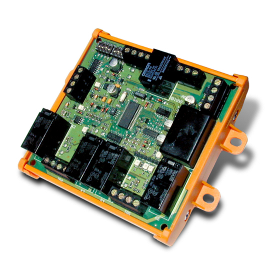
Chapter 1: Product design Introducing the GSA-REL Description The GSA-REL Releasing Module (Figure 1) is a Signature Series component consisting of: • Two supervised release circuits • Two supervised prerelease circuits • One supervised manual release input circuit • One zone relay output (Form C contact) •... -
Page 12: Fire Suppression Systems
Fire suppression systems Sprinkler systems The GSA-REL works with two types of sprinkler systems: deluge and preaction. The primary difference between these systems is the type of sprinkler head (or nozzle) that terminates the pipes. Table 1 outlines the Factory Mutual Research Corporation (FM) requirements for deluge and preaction systems. - Page 13 Carbon dioxide NFPA 12 Halon 1301 NFPA 12A Sprinklers NFPA 13 Water spray NFPA 15 Foam-water NFPA 16 Dry chemicals NFPA 17 Clean agent NFPA 2001 Table 3 outlines the FM requirements for automatic fire extinguishing systems. GSA-REL Technical Reference Manual...
-
Page 14: Compatible Panels And Devices
Compatible panels and devices Panels The GSA-REL is compatible with MIR2 and QuickStart fire alarm control panels. The GSA-REL must be installed in an enclosure dedicated to the releasing system. No other devices may be installed in the enclosure. You can install the GSA-REL in any of the following enclosures: •... - Page 15 Refer to the control panel documentation for a list of compatible appliances. Note that the GSA-REL is not designed to generate an NFPA 72 standard alarm evacuation signal, and does not meet UL 864 requirements for an audible alarm notification circuit intended for evacuation.
- Page 16 Abort stations The GSA-REL requires normally-open, momentary-action abort stations. The abort station controls only the GSA-REL to which it is connected. Abort stations must be listed with the appropriate agencies in your area. See the heading “Listing agencies” on page 9.
- Page 17 LV2LBX25 73218BN4UNLVNOC111C2 73212BN4TNLVNOC322C2 71395SN2ENJ1NOH111C2 Viking 11596 Listing agencies Listing agencies whose codes and standards may apply in your area include: • Factory Mutual Research Corporation (FM) • Underwriters Laboratories, Inc. (UL) • Underwriters Laboratories Canada (ULC) GSA-REL Technical Reference Manual...
-
Page 18: Specifications
Chapter 1 Product design Specifications Table 6: GSA-REL specifications Power riser Input voltage 18.4 to 27.4 VDC Supervisory current 25 mA, max. Alarm current 190 mA min., 4 A max. (depends on output circuit loading) Line resistance See Table 7... - Page 19 [1] Riser current: The total current of the prerelease and release circuits is limited to 3.83 A. This is the power riser maximum input current of 4 A, minus 170 mA. Table 7: Power riser Total riser Distance from GSA-REL to power supply Wire current (A) resistance [1] 12 AWG 2.5 sq mm...
- Page 20 REL. Abort station The abort station controls only the GSA-REL to which it is connected. However, activation of the abort switch must be annunciated at all panels in a network.
-
Page 21: Application Block Diagrams
“Specifications,” earlier in this chapter. Preaction or deluge sprinkler systems Figure 2 illustrates the integration of the GSA-REL with the fire alarm control panel and a preaction or deluge sprinkler system. Sprinkler systems do not include service disconnect stations, abort stations, or manual release stations. - Page 22 The GSA-REL also supports automatic extinguishing systems, which provide manual actuation of abort, release, and service-disconnect functions. Figure 3 illustrates the integration of the GSA-REL with a fire alarm control panel in an automatic fire extinguishing system. Figure 3: Integration of the GSA-REL with an automatic extinguishing system...
-
Page 23: Fire Suppression Application
Chapter 1: Product design Fire suppression application The GSA-REL includes two releasing circuits, which can provide fire suppression in two separate areas. The releasing circuits operate in unison and cannot be controlled separately. The computer room illustrated in Figure 4 is a typical application for the Releasing Module. -
Page 24: Release Sequences
“Programming” for details on AND group rules. To create AND groups, see the MIR2 System Programming Manual and the MIR2-SDU Online Help. The GSA-REL horn circuit is not designed to generate an NFPA 72 standard alarm evacuation signal, and does not meet UL 864 requirements for audible alarm notification circuits intended for evacuation. - Page 25 (steady). The automatic delay timer expires and the release circuits activate. A manual reset at the fire alarm control panel deactivates the release solenoids and the Releasing Module returns to the normal state. GSA-REL Technical Reference Manual...
- Page 26 (steady). The manual delay timer expires and the release circuits activate. A manual reset at the fire alarm control panel deactivates the release solenoids and the Releasing Module returns to the normal state. GSA-REL Technical Reference Manual...
-
Page 27: Installation
Chapter 2 Installation Summary This chapter shows you how to mount and wire the GSA-REL. When you install the GSA-REL, be sure to follow agency and local requirements along with the instructions in this manual. Content Mounting the GSA-REL 20... -
Page 28: Mounting The Gsa-Rel
GSA-REL. To mount the GSA-REL in an MFC-A cabinet: 1. Align the GSA-REL to the designated mounting holes in the MFC-A (Figure 7 and Figure 8). 2. Secure the GSA-REL to the MFC-A using the screws and washers provided. - Page 29 Chapter 2: Installation Figure 8: MFC-A/GSA-REL footprint Conduit knockout MFC-A Releasing Module footprint Conduit knockout Figure 9: GSA-REL mounting holes in compatible cabinets Releasing Module Interior surface of enclosure Notes #6-32 Mounting space Self-tapping [1] Mark the mounting hole locations...
-
Page 30: Setting Abort Mode And Delay Times
10 seconds. Setting the DIP switches Figure 10 shows the default DIP switch settings of the GSA-REL. DIP switch settings for the GSA-REL abort modes and delay time settings are shown in Table 11 through Table 14. - Page 31 Chapter 2: Installation Figure 10: GSA-REL DIP switches 1 = On 0 = Off 0 0 0 1 1 0 0 1 Releasing Module 1 2 3 4 5 6 7 8 Table 11: Abort mode settings Abort mode 1 (Default)
-
Page 32: Reading The Leds
Chapter 2: Installation Reading the LEDs Figure 11 shows the location of the LEDs on the GSA-REL. These are labeled DS1 through DS7. Figure 11: GSA-REL LEDs Releasing Module Table 15: GSA-REL LEDs Color Pattern Function Flashing Data (alarm conditions) -
Page 33: Wiring The Gsa-Rel
Caution: Do not connect the releasing solenoids before the system has been programmed and tested, and the Signature loop controller and GSA-REL have reached their normal state. See Chapter 3 “Programming” and Chapter 4, “Testing and troubleshooting” for details. Failure to follow these instructions can result in unexpected release of the fire suppression agent. - Page 34 Chapter 2: Installation Figure 12: GSA-REL wiring Manual release circuit [12] Abort circuit [12] Zone relay output [10] [8] [9] Class B Class A or Class B Signature Data Circuit [8] [13] [14] 24 VDC in 24 VDC out Releasing Module...
- Page 35 Listed 24 VDC nonpolarized valve. The releasing solenoid valve wiring is not supervised. Run the connection to the valve in conduit within 20 feet of the RELA-EOL relay. Polarity of circuit shown in supervisory state. On alarm, polarity reverses. Supervised and power-limited. See “ GSA-REL Technical Reference Manual...
- Page 36 RELA-EOL Personality: (3) Active B Text 1: REL1 RELEASE 1 Text 2: DISCONNECT SW ( ) ( ) ( ) ( ) DATA IN from DATA OUT to previous device next device GSA-REL Technical Reference Manual...
-
Page 37: Warning Notice Placards
To ensure safety with the GSA-REL: • Copy Figure 15. Cut out the photocopied placard along the perforated line, and post it next to the GSA-REL. • Copy Figure 16. Cut out the photocopied placard along the perforated line, and post it next to the fire alarm control panel. - Page 38 Chapter 2: Installation Figure 15: GSA-REL warning notice WARNING! Disconnect all wiring on TB4 of the Releasing Module (release circuits 1 and 2) during system service. Disabled points will not prevent activation of the release circuits. Failure to follow these instructions may result in loss of life, serious injury, or property damage.
- Page 39 All releasing circuits must be returned to their normal operating conditions upon completion of system test or service. Failure to follow these instructions may result in loss of life, serious injury, or property damage. GSA-REL Technical Reference Manual...
- Page 40 Chapter 2: Installation GSA-REL Technical Reference Manual...
-
Page 41: Programming
Read the configuration and programming topics that apply to your fire alarm system. GSA-REL programming is almost identical for all systems. The greatest differences exist in the rules required and the configuration of AND groups. The GSA-REL programming steps require strict adherence. Follow each instruction carefully. -
Page 42: Programming The Gsa-Rel In The Mir2-Sdu
Incorrect programming may result in loss of life, serious injury, or property damage. The GSA-REL is a single module with six serial numbers. Addresses will differ for each installation, but they must be consecutive. Note: If you are adding other Signature Series devices to the project database, add the GSA-REL last. - Page 43 6. In the Signature Series mapping tool, open the Actual vs. Expected Data dialog box (F9 key). 7. For the first two GSA-REL devices, click Commit Expected. 8. For the third GSA-REL device, click Break Chain, select the first available address (the release circuit), and click Commit Expected. Break chain button 9.
- Page 44 0212 Prerelease_2 Prerelease_2 GSA-REL [1] These addresses illustrate that the GSA-REL should occupy six consecutive addresses. The actual addresses in your system may differ. Creating an abort confirmation LED WARNING: If the abort circuit is shorted, the system interprets this as a manual abort.
- Page 45 CONFIRMATION DOORCONTROL 'RELEASE_1' : ON LED 'LED_1_2'; [ABORT LED] MONITOR MONITOR 'ABORT' : ON LED 'LED_1_3'; Caution: Do not program the Drill switch to test the GSA-REL. Notes • [ALARM_1] and [ALARM_2] require the addition of two Signature Series alarm devices to the SDC Configuration. Make sure that the object labels in the rules match the labels assigned in the Object Configuration.
-
Page 46: Programming The Gsa-Rel In The Qs-Cu
2. The smoke detectors must have their primary and alternate verification properties set to None. The GSA-REL has six addressable circuits. To add the GSA-REL to the loop controller database, you must add three GSA-RELs. The first GSA-REL is for the abort switch and manual release switch circuits, the second for the two release circuits, and the third for the two prerelease circuits. - Page 47 1. Click Configure, and then click Cabinets. 2. Select the SLIC connected to the GSA-REL, and then click Configure. 3. Click the Modules tab, and then set the Quantity box to 1. 4. Enter the following information:...
- Page 48 2. Click the Zones tab, and then click Add Zones. 3. Click the Members tab, and then click Add Device. 4. Select only the devices required to activate the GSA-REL prerelease circuits, and then click OK. GSA-REL Technical Reference Manual...
- Page 49 Add the prerelease response, create the delay, and then add the release response in that order. 1. Click the Devices tab, and then select the circuit labeled GSA-REL A002 MAN RELEASE. GSA-REL Technical Reference Manual...
- Page 50 5 and 6, the prerelease relay. Configure the GSA-CT2 module as follows: 1st Device represents 1st Device Type: Monitor 1st Personality:(3) Active B 1st Text 1: REL1_RELEASE 1st Text 2: CKT_ACTIVE 2nd Device Type: Monitor 2nd Personality:(3) Active B GSA-REL Technical Reference Manual...
- Page 51 Step 11: Retrieve the loop data from the SLIC 1. Click Configure, and then click Cabinets. 2. Select the SLIC connected to the GSA-REL, and then click Configure. 3. Set the Communications Port setting for the COM port used to connect the service computer to the control panel.
- Page 52 REL in the string. 3. If the serial number displayed in the Module Properties dialog is not the same as the serial number shown on the bar code attached to the GSA-REL, click Close, and then double-click the next REL in the string.
-
Page 53: Testing And Troubleshooting
Code requirements for testing 46 System testing 46 Checking your work 46 Testing MIR2 systems 47 Testing QuickStart systems 47 Connecting the releasing solenoids 47 GSA-REL fault messages on MIR2 panels 48 GSA-REL fault messages on QuickStart panels 49 GSA-REL Technical Reference Manual... -
Page 54: Code Requirements For Testing
Some events after a download or an upload may destabilize the system enough to activate the release circuits. Do not connect the releasing solenoids until system testing is complete and the system is stable. Check your installation and programming work before you connect the releasing solenoids. GSA-REL Technical Reference Manual... - Page 55 If not, a second Reset switch activation may be necessary. Avoid using the Drill switch to test the GSA-REL. If you activate a Drill, press the Reset switch to deactivate it. The deactivation of the Drill switch, alone, does not silence the prerelease tones.
-
Page 56: Gsa-Rel Fault Messages On Mir2 Panels
Signature Series Configuration Form. Select the Status tab. In the Mapping Progress group, the Expected and Actual numbers should match. 3. Check the DS1, DS3, and DS7 LEDs on the GSA-REL to make sure that it is not active. There should be no red or yellow LEDs. Check the output terminals with a voltmeter prior to connecting the releasing solenoids. -
Page 57: Gsa-Rel Fault Messages On Quickstart Panels
When programming is complete, the control panel resets itself and maps the line controller card. During the reset, device supervision may cause the panel to generate a common trouble message for each GSA-REL circuit. This is a normal indication, and should clear within minutes. Table 20 lists other messages related to the GSA-REL. - Page 58 Chapter 4: Testing and troubleshooting Table 20: GSA-REL fault messages Device Condition LCD message Abort Short Monitor Monitor (Abort) Open Trouble Trouble ABORT SW [1] Help message: TROUBLE OPEN Manual Short Alarm Alarm Active MAN RELEASE [1] Open Trouble Trouble...
-
Page 59: Index
15 adding circuits to QS-CU projects, 39 configuring abort delay time, 23 addresses configuring abort mode, 22, 23 MIR2-SDU, 35 configuring AND groups QS-CU, 40 MIR2-SDU, 36 agencies, listing, iv, 9 QS-CU, 38, 41 GSA-REL Technical Reference Manual... - Page 60 FM requirements automatic fire extinguishing systems, 6 deluge and preaction systems, 4 M276A-REL manual release station, 7 footprint of GSA-REL, 21 M278A-REL manual release station, 7 manual delay time, 23 manual delay timer, 18 manual release circuit, 10, 26, 39...
- Page 61 34, 35 QS-CU, 40 Accept Actual command, 35, 36 silencing, 43 adding a GSA-REL, 34 specifications, 10 configuration settings for GSA-REL, 35 wiring lengths, 11 Drill switch, 37 prerelease horn circuit, 17, 18 programming, 34 prerelease NACs, 47...
- Page 62 MIR2, 48 MIR2-SDU, 35, 36 disconnecting in QuickStart, 49 QS-CU, 43, 44 manual release sequence, 18 Signature data circuit, 11, 26 on the GSA-REL, 13 Signature map QS-CU, 39 MIR2-SDU, 36 specifications, 10 QS-CU, 44 wiring diagram, 26...
- Page 63 NAC circuit, 26 warning notice placards, 29 wet pilot sprinkler line, 4 wire lengths, 11 wire separation, 20 wiring diagram, 26 wiring the GSA-REL, 25 writing rules MIR2-SDU, 37 zone relay compliance requirements, 11 output circuit, 26 output specifications, 10...
- Page 64 Index GSA-REL Technical Reference Manual...
Need help?
Do you have a question about the GSA-REL and is the answer not in the manual?
Questions and answers