Table of Contents
Advertisement
Quick Links
INSTRUCTIONS FOR SAFE OPERATION AND MAINTENANCE
WARNING
TASK FORCE TIPS, Inc.
MADE IN USA •www.tft.com
©Copyright Task Force Tips, Inc. 2002-2005
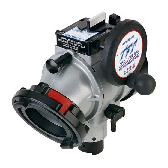
MANUAL: Ball Intake Valve™
Read instruction manual before use. Operation of this device without
understanding the manual and receiving proper training is a misuse of this
equipment. A person who has not read and understood all operating and safety
instructions is not qualified to operate the Ball Intake Valve.
This instruction manual is intended to familiarize firefighters and maintenance
personnel with the operation, servicing and safety procedures associated with
the Ball Intake Valve.
This manual should be kept available to all operating and maintenance
personnel.
www.tft.com
®
1-219-462-6161
1-800-348-2686
A1306
2800 E. Evans Ave, Valparaiso, IN 46383-6940 USA
800-348-2686 • 219-462-6161 • Fax 219-464-7155
OPERATING RANGE:
Pressure Max 250 PSI
Pressure Min Full Vac.
Hydrostatic
Proof Test:
900 PSI
LIA-200 December 9, 2005 Rev 08
Advertisement
Table of Contents

Related Manuals for TFT Ball Intake Valve


Summary of Contents for TFT Ball Intake Valve
- Page 1 A person who has not read and understood all operating and safety instructions is not qualified to operate the Ball Intake Valve. This instruction manual is intended to familiarize firefighters and maintenance personnel with the operation, servicing and safety procedures associated with the Ball Intake Valve.
- Page 2 DRAWINGS AND PARTS LISTS manufacturer’s instructions. MAINTENANCE 6. Failure to follow these guidelines may result in death, burns or other 10.0 BALL INTAKE VALVE PRESSURE LOSS severe injury. 11.0 WARRANTY FEMSA Fire and Emergency Manufacturers and Services Association, Inc.
- Page 3 3.0 GENERAL INFORMATION The Ball Intake Valve is intended for use on the intake manifold of a fire engine. The valve is kept closed while the water supply from a hydrant or another pumper to the engine is being established. This prevents the pump from sucking air through the intake manifold and losing its prime.
- Page 4 5.0 USE 5.1 INTAKE ELBOW The intake elbow swivels 360 degrees to help prevent hose kinks, and make connection of suction lines easier. The intake can be turned forward or backward to help make connections in tight places if the water supply is in front of or behind the truck.
- Page 5 8.0 DRAWINGS AND PARTS LISTS 62 63 45 46 ©Copyright Task Force Tips, Inc. 2002-2005 LIA-200 December 9, 2005 Rev 08...
- Page 6 8.0 DRAWINGS AND PARTS LISTS Ball Intake Valve Parts List Index Description Part # BGIV BODY - POWDER COAT A1015 O-RING-236 3-1/4 ID 1/8 C/S VO-236 BACK RING STAINLESS STEEL A1201S VALVE SEAT A1520 PLASTIC STRIP 7.00" A1290 SEAL RETAINER A1521S COUPLING 5.0"NHF X PSF7.0-NFS...
- Page 7 8.0 DRAWINGS AND PARTS LISTS Index Description Part # COUPLING HEAD STORZ 6" X 5.25PSF *X696SX-LOCK INSERT 6.0"BSPM X PSF5.25 A4765 COUPLING HNDL 4.0"NHF X PSF5.25 A4560N COUPLING HNDL 4.5”NHF X PSF5.25 A4565N COUPLING SH 5.0"NHF X PSF7.0 NFS A1261NT MATE PSF5.25 X PSM7.0-NFS A4745 PLASTIC STRIP 5.25"...
- Page 8 TFT, at 2800 East Evans Avenue, Valparaiso, Indiana 46383, within a reasonable time after discovery of the defect. TFT will examine the equipment. If TFT determines that there is a defect attributable to it, TFT will correct the problem within a reasonable time.
Need help?
Do you have a question about the Ball Intake Valve and is the answer not in the manual?
Questions and answers