Subscribe to Our Youtube Channel
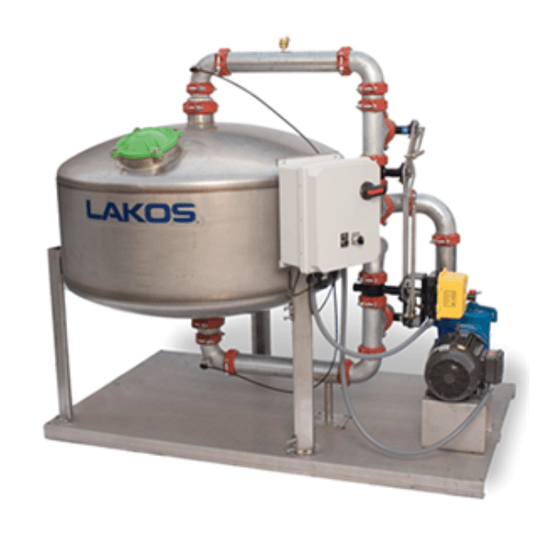
Summary of Contents for Lakos STS Series
- Page 1 Installation and Operators Manual Model: Tower System Media Filters STS FRESNO, CALIFORNIA, USA LS-644E (Rev. 12/20)
- Page 2 10%-20% based on the full- stream flow of the system. The standard STS Series Sand Filters can be filled with media for either 10 micron filtration @ 95% removal efficiency (standard), or 5 micron filtration @ 90% removal efficiency (optional).
-
Page 3: Warranty
Look for crate damage, pierced or torn boxes or any other signs of handling, which may suggest damage to the system. LAKOS STS Series Media Filters are shipped with all major components assembled onto the skid. Selected small items, such as the pressure... - Page 4 LAKOS sand media is shipped separately in 50 lb. bags and gravel shipped in 80 lb. bags. The exact number of bags is determined by the actual system size (see chart below). Do not introduce media sand or gravel into the STS system until the system is placed in its final operating position.
- Page 5 All LAKOS STS systems are configured for either Source (S) or City (C) backwash. If your system is designed for City (C) backwash, city (or other external) water supply piping will need to be plumbed to the system backwash inlet connection (see drawing STS-0002).
- Page 6 Once all pipe connections are installed and properly secure, open the STS Media filter’s top access port. Inspect the PVC underdrain to be sure all parts (laterals) and connections are secure and nothing is broken. Fill the STS about one-third to half full with water. Then, SLOWLY add the appropriate amount of sand (refer to media sand chart above).
- Page 7 STS - HOW IT WORKS SCHEMATIC The Basic Steps of Media Filtration Unfiltered system water enters the pump suction INLET. Water is pumped to top and is uniformly dispersed over the media bed. Water passes thru the media bed leaving debris behind. Filtered water exits the OUTLET.
-
Page 8: Start-Up And Operation
Positive Suction Head Required (NPSHR) to avoid air intrusion or cavitation (vortexing at point of source). See appropriate pump curve included with this manual. This is also very important when LAKOS Hydroboosters are in use Make sure that there is water in the main inlet line to provide flooded suction to the STS system pump. - Page 9 Check STS system inlet and outlet pressure gauges. Proper operating parameters will result in an inlet pressure from approximately 17-20 psi (1.2- 1.4 bar) above the system flow pressure to the STS system and an outlet pressure of 16-19 psi (1.1-1.3 bar) above the system pressure flow pressure to the STS system.
- Page 10 the suction strainer). Use a compressed air hose to remove any water trapped in the pump casing or flush the system with antifreeze. Do not replace the plugs. Store them in the strainer basket for the winter. Alternatively, remove the pump and motor from the plumbing entirely. Store them indoors in a warm and dry place.
-
Page 11: Maintenance
Isolate the strainer by closing the isolation valves installed before the pump and after the separator outlet. These are not provided as a standard option by Lakos, but are available if a valve kit is ordered. Loosen the nuts or threaded stud and remove the lid. -
Page 12: Pressure Gauges
opposite side. Wipe it clean. Whenever motor is required to be unhooked/ repaired, follow shut-off lock-out procedure and refer to the pump/motor manufacturers I&O manual as required. CONTROL PANEL/PUMP STARTER: A blown-out fuse and/or consistently kicked-back circuit breaker is indicative of a motor overloading/overheating. The built-in thermostat in the motor is experiencing an excessive rise in temperature, which might be caused by sudden voltage increase/drop, phase imbalance or over-torqued shaft. - Page 13 STS Operation and Maintenance Schedule Type of Start Up Monthly Semi- Shutdown Annually Service annually General Condition of Unit Drain Condensate As Required As Required As Required As Required from air line to Required pneumatic actuator (if applicable) Clean pre-strainer As Required As Required As Required...
-
Page 14: Troubleshooting Procedures
Bleed off trapped air in system. disruption of the media sand bed. Incorrect media sand. Replace with proper media sand. Consult your LAKOS representative. Excessively high pressure Backwash more often at lower differential before backwashing, differential pressure. which forces contaminants through filter bed. - Page 15 VII. TROUBLE SHOOTING PROCEDURES (con’t) PROBLEM POSSIBLE CAUSES SOLUTIONS Be sure wiring is connected correctly. Controller power may Automatic Replace circuit fuses. Turn on power. be off or circuit fuses tripped. Backwash Fails to Controller may be faulty and need Cycle replacement.
- Page 16 VII. TROUBLE SHOOTING PROCEDURES (con’t) POSSIBLE PROBLEM SOLUTIONS CAUSES Check and clean out pump suction pre- Suction line is not Pump will not prime flooded with water. strainer as required. (standard, not self- priming) Debris in basket Check and clean pump pre-strainer as strainer.
- Page 17 PRESSURE AT OUTLET OF SAND FILTER: BACKWASH DURATION: ADDITIONAL OBSERVATIONS/REMARKS: Please complete this form and send a copy to LAKOS; keep a copy for your records. 1365 North Clovis Avenue ~ Fresno, California 93727 USA (559) 255-1601 • Fax:(559) 255-8093 • info@lakos.com 1365 North Clovis Avenue ~ Fresno, California 93727 USA (559) 255-1601 •...


Need help?
Do you have a question about the STS Series and is the answer not in the manual?
Questions and answers