Table of Contents
Advertisement
Available languages
Available languages
Installer and user manual
CONNECT BASE MIX 1 LE
CONNECT BASE MIX 2 LE
CONNECT BASE MIX 1 LE
CONNECT BASE MIX 2 LE
ISTRUZIONI PER L'INSTALLATORE E PER IL SERVIZIO
IT
TECNICO DI ASSISTENZA
INSTRUCTIONS FOR THE INSTALLER AND FOR
EN
TECHNICAL ASSISTANCE
INSTRUKCJA MONTAŻU I OBSŁUGI
PL
CONNECT BASE MIX 1 LE
Advertisement
Chapters
Table of Contents

Related Manuals for Beretta CONNECT BASE MIX 1 LE

Summary of Contents for Beretta CONNECT BASE MIX 1 LE
- Page 1 Installer and user manual CONNECT BASE MIX 1 LE CONNECT BASE MIX 2 LE ISTRUZIONI PER L’INSTALLATORE E PER IL SERVIZIO TECNICO DI ASSISTENZA INSTRUCTIONS FOR THE INSTALLER AND FOR TECHNICAL ASSISTANCE INSTRUKCJA MONTAŻU I OBSŁUGI CONNECT BASE MIX 1 LE...
-
Page 2: Table Of Contents
CONNeCT BASe MIx 2 Le 20084766 Rinnovati ringraziamenti Beretta ACCESSORI Per gli accessori dedicati vedere il Catalogo Beretta e la scheda prodotto. CONFORmITà INDICE Il CONNECT LE è conforme a: - Direttiva Compatibilità Elettromagnetica 2004/108/CE - Direttiva Bassa Tensione 2006/95/CE GeNeRALITà... -
Page 3: Generalità
GeNeRALITà 1.1 Avvertenze generali 1.2 Regole fondamentali di sicurezza Ricordiamo che l’utilizzo di prodotti che impiegano combustibili, energia elettrica ed Al ricevimento del prodotto assicurarsi dell’integrità e della completezza della acqua comporta l’osservanza di alcune regole fondamentali di sicurezza quali: fornitura ed in caso di non rispondenza a quanto ordinato, rivolgersi all’Agenzia che ha venduto l’apparecchio. -
Page 4: Struttura
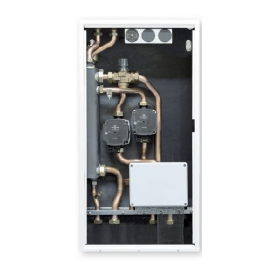
1.4 Struttura CONNECT BASE MIX 2 LE CONNECT BASE MIX 1 LE Rubinetto di scarico 10 Valvola miscelatrice impianto bassa temperatura 2 Bottiglia di miscela 11 Circolatore impianto bassa temperatura 2 Circolatore impianto bassa temperatura 1 12 Scatola connessioni elettriche... -
Page 5: Dati Tecnici
4 1.7 Attacchi idraulici Le caratteristiche degli attacchi idraulici sono le seguenti: CONNECT BASE MIX 2 LE CONNECT BASE MIX 1 LE Entrata dalla caldaia (Ø 3/4”) Uscita dalla caldaia (Ø 3/4”) Mandata impianto diretto alta Uc Ec temperatura (Ø... -
Page 6: Circolatori
1.8 Circolatori è equipaggiato di circolatori ad alta efficienza e controllo elettronico le cui prestazioni, da utilizzare per il dimensionamento degli impianti, sono riportate nel CONNECT LE grafico. Prevalenza utile del circolatore Potenza assorbita dal circolatore Portata (m Portata (m Prevalenza residua disponibile all’impianto Prevalenza residua disponibile all’impianto ALTA TEmPERATURA... -
Page 7: Schemi Elettrici
1.9 Schemi elettrici 1.9.1 Schema elettrico CONNeCT Le BASe MIx 2 INGRESSO RICHIESTA CALORE CALDAIA o GENERATORE 5-24 4-14 4-14 5-24 4-14 5-24 marrone marrone marrone marrone marrone marrone nero 3/14 nero nero 4/11 nero 6-21 3-11 3-11 6-21 3-11 6-21 marrone marrone... -
Page 8: Schema Elettrico Connect Le Base Mix 1
1.9.2 Schema elettrico CONNeCT Le BASe MIx 1 INGRESSO RICHIESTA CALORE CALDAIA o GENERATORE 5-24 4-14 4-14 5-24 marrone marrone marrone marrone nero 3/14 nero nero 4/11 nero 3-11 6-21 6-21 3-11 marrone marrone marrone marrone A2 blu marrone marrone marrone Fusibile 3.15A F TA1 rosso... -
Page 9: Installazione
INSTALLAZIONE 2.2 Dimensioni e pesi 2.1 Ricevimento del prodotto Il CONNECT LE (1) viene fornito in collo unico protetto da un imballo in cartone (2) all’interno del quale si trova una busta di plastica che contiene: - Rampe collegamenti idraulici (3) verso il generatore di calore - Termometri (4), per le sole zone di bassa temperatura, e clip fissaggio dei rispettivi bulbi - Staffa (5) e scatola cablaggi (6) - Page 10 Per l’installazione del CONNECT LE all’interno del box, effettuare le seguenti opera- - Fissare, utilizzando le apposite clip, i bulbi dei termometri con questa sequen- zioni: za (partendo dal lato sinistro): termometro (T1) alla rampa (C1) posta sotto - Inserire il lato destro del CONNECT LE all’interno del box e ruotare il lato si- il circolatore impianto BT1 e termometro (T2) alla rampa (C2) posta sotto il nistro fino a far entrare completamente il CONNECT LE facendo attenzione a circolatore impianto BT2...
-
Page 11: Zone Minime Di Rispetto
2.4 zone minime di rispetto 2.5 Schema di principio installazione tipica La figura mostra un esempio tipico di installazione del CONNECT LE . NOTA: Per l’installazione di eventuali rubinetti (non forniti) occorre predisporre la nic- chia di dimensione tale da poterli installare sotto il CONNECT LE stesso. Caldaia Caldaia 230V~50Hz... -
Page 12: Collegamenti Elettrici
2.6 Collegamenti elettrici CONNECT LE BASE MIX 1 Il CONNECT LE è predisposto con dei passacavi in gomma (1) posti nella parte supe- riore del box per il passaggio dei cablaggi elettrici. TA1 rosso TA3 grigio supply cable input 230V Di seguito verrà... -
Page 13: Messa In Servizio
mESSA IN SERVIZIO Indicazione dello stato di allarme Se il circolatore ha rilevato uno o più allarmi il LED bicolore (B) è rosso. I quattro LED gialli (C) indicano la tipologia di allarme come evidenziato nella tabella seguente. Descrizione Stato Eventuale 3.1 Prima messa in servizio Stato LED... - Page 14 Prevalenza proporzionale visualizzazione Il circolatore lavora in funzione della domanda di calore dell’impianto. Il punto di lavoro stato di del circolatore e la curva di prevalenza proporzionale selezionata si sposteranno in > 2 s impostazione funzionamento funzione della domanda di calore del sistema. visualizzazione impostazione 10 s...
-
Page 15: Impostazione Impianto Bassa Temperatura
3.3 Impostazione impianto bassa temperatura 4.2 Svuotamento del CONNECT LE Fissare la temperatura di mandata dell’impianto bassa temperatura regolando ma- Prima di iniziare le operazioni di svuotamento posizionare l’interruttore generale su nualmente la valvola miscelatrice riferendosi alla tabella seguente. “spento”. Per svuotare il CONNECT LE : Posizione manopola Temperatura (°C) - Page 16 CONNeCT BASe MIx 2 Le 20084766 Thank you once again Riello S.p.A. ACCESSORIES Please refer to the Beretta price list and the product information sheet for the CONFORmITy specific accessories. The CONNECT LE conforms to: TABLe OF CONTeNTS - Electromagnetic Compatibility (EMC) Directive 2004/108/EC - Low Voltage Directive 2006/95/EC GeNeRAL.
-
Page 17: General
( CONNeCT BASe MIx 1 Le ) or three zones ( CONNECT BASe MIx 2 Le ) which are at different temperatures. -
Page 18: Structure
1.4 Structure CONNECT BASE MIX 2 LE CONNECT BASE MIX 1 LE Drain cock 10 Mixing valve low temperature system 2 Mixing bottle 11 Circulation unit low temperature system 2 Circulation unit low temperature system 1 12 Electrical connection box... -
Page 19: Technical Data
1.7 Plumbing connections The characteristics of the plumbing connections are as follows: Inlet from boiler (Ø 3/4”) CONNECT BASE MIX 2 LE CONNECT BASE MIX 1 LE Outlet to boiler (Ø 3/4”) High temperature system delivery line (Ø 3/4”) Mbt1... -
Page 20: Circulation Units
1.8 Circulation units is equipped with high efficiency electronically controlled circulation units. The performance data of these units to be used to size the system is shown in the graph. CONNECT LE Available head of the circulation unit Power absorbed by the circulation unit Flow rate (m3/h) Flow rate (m3/h) Residual head available to the system... -
Page 21: Wiring Diagram
1.9 Wiring diagram 1.9.1 CONNeCT Le 2 BASe 2 MIx wiring diagram INGRESSO RICHIESTA CALORE CALDAIA o GENERATORE 5-24 4-14 4-14 5-24 4-14 5-24 marrone marrone marrone marrone marrone marrone nero 3/14 nero nero 4/11 nero 6-21 3-11 3-11 6-21 3-11 6-21 marrone... -
Page 22: Connect Le Base Mix 1 Wiring Diagram
1.9.2 CONNeCT Le BASe MIx 1 wiring diagram INGRESSO RICHIESTA CALORE CALDAIA o GENERATORE 4-14 5-24 4-14 5-24 marrone marrone marrone marrone nero 3/14 nero nero 4/11 nero 3-11 6-21 6-21 3-11 marrone marrone marrone marrone A2 blu marrone marrone marrone Fusibile 3.15A F TA3 grigio... -
Page 23: Installation
INSTALLATION 2.2 Dimensions and weights 2.1 Receiving the product The CONNECT LE (1) is supplied in one package, protected by cardboard packaging (2) inside of which there is a plastic envelope containing: - Plumbing connection ramps (3) towards the heat generator - Thermometers (4), only for low temperature zones and retaining clip for the relative bulbs - Brackets (5) and wiring case (6) - Page 24 To install CONNECT LE inside the box, proceed as follows: - Using the designated clips, secure the thermometer bulbs following the se- - Insert the right side of the CONNECT LE inside the box and rotate the left side quence (from left to right): thermometer (T1) to the ramp (C1) located below until the CONNECT LE enters completely making sure that the insulator cover- the BT1 system circulation unit and the thermometer (T2) to the ramp (C2) ing the mixing bottle is not damaged...
-
Page 25: Minimum Distances
2.4 minimum distances 2.5 Typical installation layout The figure shows an example of a typical installation of the CONNECT LE . N.B.: For the installation of any cocks, (not supplied), a niche must be formed of a sufficient size to allow them to be fitted below the CONNECT LE itself. Boiler Boiler 230V~50Hz... -
Page 26: Electrical Connections
2.6 Electrical connections CONNeCT Le 1 MIx The CONNECT LE is prearranged with rubber cable feed-throughs (1) located in the top section of the box allowing wiring to be passed through. TA3 grigio TA1 rosso supply cable input 230V TBT 1 Below is an explanation of how to correctly connect the CONNECT LE to the various devices and the boiler. -
Page 27: Commissioning
COMMISSIONING Indication of the alarm status If the circulation unit has detected one or more than one alarm, the two-colour LED (B) is red. The four yellow LEDs (C) indicate the type of alarm as shown in the table below. ALARm CIRCULATION Possible... - Page 28 operating status display > 2 s setting LOW proportional head curve setting AVERAGE proportional head curve display HIGH proportional head curve 10 s Constant head The circulation unit works at constant head, irrespective of the heat request. The work- ing point of the circulation unit will move along the selected curve on the basis of the heat request.
-
Page 29: Setting The Low Temperature System
3.3 Setting the low temperature system 4.2 Draining the CONNeCT Le Set the low temperature system delivery temperature by manually adjusting the mixing Before starting draining operations, set the main switch to "off". valve and referring to the following table. To drain the CONNECT LE : - Close the shut-off cocks on the side of the system (if present) Knob position... - Page 30 Schemat podłączeń elektrycznych CONNECT BASE MIX 2 LE ..35 1.9.2. Schemat podłączeń elektrycznych CONNECT BASE MIX 1 LE ..36 UWAGI DLA UŻYTKOWNIKA: urządzenie nie wymaga jakiejkolwiek regulacji lub kontroli ze strony użytkownika. W związku z tym zabrania się otwierania przedniej INSTALACJA .
-
Page 31: Informacje Ogólne
CONNeCT BASe MIx Le jest rozdzielaczem hydraulicznym, który może być stosowa- ny w połączeniu z każdym kotłem; służy do rozdzielenia obiegów grzewczych na dwie (CONNeCT BASe MIx 1 Le) lub trzy strefy (CONNeCT BASe MIx 2 Le) mające różne temperatury. Zestaw składa się ze sprzęgła hydraulicznego, płyty elektronicznej, dwóch/ trzech modulowanych pomp obiegowych i jednego/dwóch 3-drogowych termostatycznych... -
Page 32: Budowa
1.4 Budowa CONNECT BASE MIX 2 LE CONNECT BASE MIX 1 LE Zawór spustowy 10 Zawór mieszający obiegu niskotemperaturowego 2 Sprzęgło hydrauliczne 11 Pompa obiegowa obiegu niskotemperaturowego 2 Pompa obiegowa obiegu niskotemperaturowego 1 12 Skrzynka przyłączy elektrycznych Pompa obiegowa obiegu wysokotemperaturowego 1 13 Automatyczne przestawianie termostatu granicznej temperatury Zawór zwrotny (wewnątrz rury) -
Page 33: Dane Techniczne
Temperatura otoczenia wymagana do instalacji °C wyższa niż 4 1.7 Przyłącza hydrauliczne Opis i wymiary przyłączy hydraulicznych: CONNECT BASE MIX 2 LE CONNECT BASE MIX 1 LE Zasilanie z kotła (Ø 3/4”) Powrót do kotła (Ø 3/4”) Zasilanie strefy wysokotem- peraturowej (ogrzewania Uc Ec grzejnikowego) (Ø... -
Page 34: Pompy Obiegowe
1.8 Pompy obiegowe CONNECT LE jest wyposażony w energooszczędne, sterowane elektronicznie pompy obiegowe. Dane dotyczące osiągów tych pomp niezbędne do zwymiarowania instalacji przedst- awiono na wykresach Wysokość podnoszenia Pobór mocy przez pompę obiegową Natężenie przepływu (m3/h) Natężenie przepływu (m3/h) Wysokość podnoszenia w obiegu Wysokość... -
Page 35: Schemat Podłączeń Elektrycznych
1.9 Schemat podłączeń elektrycznych 1.9.1 Schemat podłączeń CONNeCT BASe MIx 2 Le INGRESSO RICHIESTA CALORE CALDAIA o GENERATORE 5-24 4-14 4-14 5-24 4-14 5-24 marrone marrone marrone marrone marrone marrone nero 3/14 nero nero 4/11 nero 6-21 3-11 3-11 6-21 3-11 6-21 marrone... -
Page 36: Schemat Podłączeń Elektrycznych Connect Base Mix 1 Le
1.9.2 Schemat podłączeń CONNeCT BASe MIx 1 Le INGRESSO RICHIESTA CALORE CALDAIA o GENERATORE 4-14 5-24 4-14 5-24 marrone marrone marrone marrone nero 3/14 nero nero 4/11 nero 3-11 6-21 6-21 3-11 marrone marrone marrone marrone A2 blu marrone marrone marrone Fusibile 3.15A F... -
Page 37: Instalacja
INSTALACJA 2.2 Wymiary i waga 2.1 Odbiór urządzenia CONNECT LE (1) jest dostarczany w opakowaniu kartonowym (2) wewnątrz, którego znajduje się opakowanie z tworzywa sztucznego zawierające: - Przyłącza hydrauliczne (3) do kotła - Termometry (4), tylko dla stref niskiej temperatury i zacisk mocujące - Uchwyty (5) i skrzynkę... - Page 38 W celu zamontowania zestawu CONNECT LE w obudowie należy postępować w nas- - Przy pomocy przeznaczonych do tego zacisków, zamocować sondy ter- tępujący sposób: mometrów przestrzegając kolejności (od lewej do prawej): termometr (T1) do - Wsunąć prawy bok CONNECT LE do obudowy i obracać lewy bok dopóki przyłącza (C1) znajdującego się...
-
Page 39: Minimalne Odległości
2.4 Minimalne odległości 2.5 Typowy przykład instalacji Poniższy schemat przedstawia przykład typowej instalacji CONNECT LE. Uwaga: W celu instalacji jakichkolwiek zaworów (nie będących na wyposażeniu) należy przewidzieć dodatkową przestrzeń umożliwiającą ich zamontowanie poniżej zestawu CONNECT LE Kocioł Kocioł 230V~50Hz IBT1 strefa 1 TA-CT1 IBT2... -
Page 40: Przyłącza Elektryczne
2.6 Przyłącza elektryczne CONNeCT Le 1 MIx CONNECT LE jest wyposażony w gumowe otwory przelotowe (1) znajdujące się w górnej części obudowy, umożliwiające przełożenie przez nie przewodów. TA3 grigio TA1 rosso supply cable input 230V TBT 1 Poniżej przedstawiono wyjaśnienie w jaki sposób można prawidłowo podłączyć zest- aw CONNECT LE do kotła oraz innych urządzeń. -
Page 41: Uruchomienie
URUCHOmIENIE Sygnalizacja statusu alarmu Jeśli pompa obiegowa wykryła jeden lub więcej alarmów, dwukolorowa dioda LED (B) będzie świecić na czerwono. Natomiast żółte diody LED (C) będą sygnalizować rodzaj alarmu w sposób przedstawiony w poniższej tabeli. 3.1 Pierwsze uruchomienie Status POmPy Możliwe RO- status LED Opis ALARMU... - Page 42 Wyświetlanie statusu pracy pompy > 2 s Kon guracja NISKA krzywa ciśnienia proporcjonalnego ŚREDNIA krzywa ciśnienia proporcjonalnego Wyświetlanie WYSOKA krzywa ciśnienia proporcjonalnego ustawień Ciśnienie stałe 10 s Pompa obiegowa pracuje ze wysokością podnoszenia, niezależnie od zapotrzebowa- nia na ciepło. Punkt pracy pompy obiegowej będzie przemieszczać się wzdłuż wy- branej krzywej ciśnienia stałego zgodnie z zapotrzebowaniem na ciepło.
-
Page 43: Konfiguracja Strefy Niskiej Temperatury
3.3 Konfiguracja strefy niskiej temperatury 4.2 Opróżnianie zestawu CONNeCT Le Temperaturę zasilania strefy niskiej temperatury należy ustawić ręcznie na zaworze Przed rozpoczęciem opróżniania, należy ustawić główny wyłącznik w pozycji „off” mieszającym biorąc pod uwagę wyjaśnienie oznaczeń z poniższej tabeli. (wyłączony). Aby opróżnić... - Page 48 Tel. +39 0341 277111 Fax +39 0341 277263 info@berettaboilers.com www.berettaboilers.com In order to improve its products, Beretta reserves the right to modify the characteristics and information contained in this manual at any time and without prior notice. Consumers statutory rights are not aected.
Need help?
Do you have a question about the CONNECT BASE MIX 1 LE and is the answer not in the manual?
Questions and answers