Table of Contents
Advertisement
Quick Links
User manual
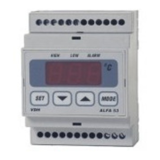
ALFANET 53
Alarm thermostat.
(With and without buzzer)
VDH doc. 080334
Software: ALFA(NET)53
* Installation.
On the connection diagram of the ALFANET 53 is shown how the sensors, power supply and
relays has to be connected. After connecting the ALFANET 53 to the power supply, a self test
function is started. As this test is finished, the measured temperature will appear on the display.
* Control.
The ALFANET 53 thermostat can be controlled by four pushbuttons on the front These keys are:
SET
- view / change set point and reset the alarm
(UP)
- increase the set point.
(DOWN) - decrease the set point.
MODE
- relays status key.
* Viewing setpoints.
Viewing Maximum alarm set point:
By pushing the SET key simultaneously with the UP key, the adjusted maximum alarm set point
will be shown.
Viewing Minimum alarm set point:
By pushing the SET key simultaneously with the DOWN key, the adjusted maximum alarm set
point will be shown.
A few seconds after releasing the SET key the set point disappears and the measured
temperature will be visible again.
* Changing the set points.
Push the SET key simultaneously with the UP or DOWN key till the maximum alarm set point or the
minimum alarm set point appears. Release the SET key.
Push the SET key again and now the set point can be changed with the UP or DOWN key. A few
seconds after releasing the keys measured temperature will be visible again.
* Status of the Relays.
By pushing the MODE key the display shows the status of the relays. Each digit shows the status
of one relay output, showing 0=off and 1=on. The code 110 means relay 1 and 2 are on and relay
3 is off.
Versie: v1.0
File: Do080334.WPD
1
Datum: 06-03-2008
Bereik: -50/+50,0
C
Advertisement
Table of Contents

Subscribe to Our Youtube Channel
Related Manuals for VDH ALFANET 53


Summary of Contents for VDH ALFANET 53
- Page 1 On the connection diagram of the ALFANET 53 is shown how the sensors, power supply and relays has to be connected. After connecting the ALFANET 53 to the power supply, a self test function is started. As this test is finished, the measured temperature will appear on the display.
- Page 2 If the required parameter is selected, the value can be read-out by pushing the SET key. Pushing the UP or DOWN key to change the value of this parameter. If 20 seconds no key is pushed, the ALFANET 53 changes to the normal operation mode. * Adjustment sensor.
- Page 3 * Parameters ALFANET 53 Para- Description Parameter Range Default meter Function Relay 1 0..7 0 = Non 1 = Minimum Control alarm 2 = Maximum Control alarm 3 = Minimum Fail safe alarm 4 = Maximum Fail safe alarm 5 = Minimum Fail safe alarm...
- Page 4 * Dimensions. * Connections.
Need help?
Do you have a question about the ALFANET 53 and is the answer not in the manual?
Questions and answers