Table of Contents
Advertisement
Quick Links
User manual
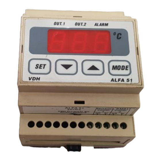
ALFA 51 PI -10/+90 C
Rail-Thermostat.
VDH doc. 070033
Software: ALFA51-PI (–10+90)
* Installation.
On the connection diagram of the ALFA 51 PI is shown how the sensors, analogue output, power supply
and relays are to be connected. After connecting the ALFA 51 PI to the power supply, a self test function
is started. As this test is finished, the measured temperature appears in the display.
* Control.
The ALFA 51 PI thermostat can be controlled by four pushbuttons on the front. These keys are:
SET
- view / change the setpoint.
UP
- increase the setpoint.
DOWN
- decrease the setpoint.
MODE
- relay status key.
* Viewing setpoint.
By pushing the SET key the setpoint appears in the display. The decimal point of the last display starts
blinking. A few seconds after releasing the SET key the setpoint disappears and the measured
temperature is shown again in the display.
* Changing setpoint.
Push the SET key and the setpoint appears in the display. Release the SET key. Now push the SET key
again together with the UP or DOWN keys to change the setpoint. A few seconds after releasing the keys
the measured temperature shows again in the display.
* Viewing the individual sensors.
By pressing the UP and DOWN key together, the individual sensors can be shown in the display. After
releasing the keys, the measured temperature of sensor-1 can be shown by pushing the UP key or the
measured temperature of sensor-2 can be shown by pushing the DOWN key. A few seconds after
releasing the keys the (average) temperature shows again in the display.
* Status of the Relays.
By pushing the MODE key the display shows the status of the relays. Each display segment shows the
status of the relay output, showing 0=off and 1=on. The code 110 means relay 1 and 2 are on and relay 3
is off.
Version: v1.0
File: Do070033.WPD
1
Date: 27-09-2007
Range: -10/+90,0C
Advertisement
Table of Contents

Related Manuals for VDH ALFA 51 PI


Summary of Contents for VDH ALFA 51 PI
- Page 1 On the connection diagram of the ALFA 51 PI is shown how the sensors, analogue output, power supply and relays are to be connected. After connecting the ALFA 51 PI to the power supply, a self test function is started. As this test is finished, the measured temperature appears in the display.
- Page 2 If the required parameter is selected, the value can be read-out by pushing the SET key. Pushing the UP or DOWN key to change the value of this parameter. If after 20 seconds no key is pushed, the ALFA 51 PI changes to the normal operation mode. * Adjustment sensors.
- Page 3 * Parameters ALFA 51 PI Para- Description Parameter Range Standard Meter value Function Relay 1 1 = Cool 2 = Heat 3 = Alarm Function Relay 2 1 = Cool 2 = Heat 3 = Alarm Function Relay 3 1 = Cool...
- Page 4 * Dimensions. * Connections. * Address. VDH Products BV Tel: +31 (0)50 30 28 900 Produktieweg 1 Fax: +31 (0)50 30 28 980 9301 ZS Roden Email: info@vdhproducts.nl The Netherlands Internet: www.vdhproducts.nl...
Need help?
Do you have a question about the ALFA 51 PI and is the answer not in the manual?
Questions and answers