Table of Contents
Advertisement
Quick Links
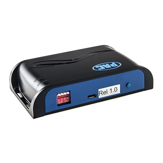
BCI-CH21
Introduction & Features
Class 2
VPW
Arbitration
J1850
1 0 0 0 1 1 1 0 1 1 1 1 0 0 1 0 0 1 1 0 1 1 0 0
The BCI-CH21 will program your Chrysler / Dodge / Jeep radio to allow the addition of a reverse camera input if the
vehicle is not equipped with one from the factory (reverse camera sold separately). The BCI-CH21 will allow the factory
navigation features of your radio to be used by the passenger at anytime. The interface also offers extra features such
as: adding Blind Spot Cameras, Front Camera, VES activation & Audio/Video input capabilities.
Important Notes
1.
It is very important to follow the exact sequence of installation steps as listed below. Failure to do so will result in the interface not
working as intended.
2.
If you change the dipswitch settings, you must disconnect and reconnect power for the change to take effect
3.
To activate the Blind Spot Camera input, a VS41 (sold separately) must be connected.
4.
To activate the Front Camera input, a VS41 (sold separately) must be connected in addition to turning on DIP switch 4
5.
The navigation unlock feature must be activated every time the key is cycled.
6.
The AVS21 A/V switcher must be used in order to use more than one video source with the BCI-CH21.
7.
If the vehicle is equipped with an external VES Player, the RCAs labeled "Audio/Video To Head Unit" will not allow an additional input
to the head unit. You must use the factory A/V aux in located in the rear of the vehicle.
8.
If the vehicle's reverse lights come on when the reverse camera feature is engaged the diode is not wired properly. Please refer to "Fig.
C" on page two for proper diode wiring.
9.
If the factory radio does not come on or "flickers" off & on, the factory amplifier does not turn on or you are receiving audio on only one
side of the vehicle, please make sure that the male pins in the BCI-CH21 plug are not bent or out of place.
10. In order to see the text generated by the BCI-CH21 on the multi-function display (MFD), it must be set to display audio text.
Set DIP switches to the ON position to activate the corresponding features.
Set DIP switches to the OFF position for any features that are not desired.
Aftermarket Reverse Camera
1 2 3 4
DIP
ON
1.
Turn on the DIP switches that correspond with the features you want to add.
These dipswitches must be set to the proper configuration before connecting the
interface to the vehicle.
2.
Depending on the vehicle you are installing the BCI-CH21 into, you may need to
cut the white/red loop in the harness. Please refer to the chart to the right to see if
you need to cut the loop. If your vehicle is listed, cut the loop. If not, do not cut the
loop. Please see the Troubleshooting section on page 4 for further explanation of
the loop and its purpose.
3.
If the vehicle is not equipped with an MFD or external Uconnect module mount
the LED in a location that is visible to the driver. In vehicles equipped with a Multi-
Function Display (MFD) in the instrument cluster or an external Uconnect module
it is not necessary to connect and mount the LED. The best way to determine if
the UConnect is external is if the vehicle has an external iPod or USB input (not
including the one built into the front of the radio).
4.
Remove the factory radio and disconnect the factory harness(es).
5.
Connect the BCI-CH21 harness to the back of the factory radio.
6.
If adding reverse camera or additional A/V inputs, connect the BCI-CH21-AUX
Harness to the back of the factory radio.
7.
Connect the aftermarket reverse camera's video output to the female yellow RCA
located on the radio side of the BCI-CH21-AUX harness. Use the BCI-CH21's
red camera turn on wire to power the aftermarket reverse camera. If you are only
using the BCI-CH21 as a navigation unlock, this step is not necessary.
Pacific Accessory Corporation
J1850
EOD
CRC
Class 2
1 1 1 0 1 0 0 0 0 1 1 0 1 1 0 1 1 1 0 0 1 1 0 0
Navigation Unlock
1
PAC
| Ph. 866-931-8021 | support@pac-audio.com
®
©2016 Pacific Accessory Corporation
www.pac-audio.com
Reverse Camera Input and Navigation Unlock
Interface for Chrysler / Dodge / Jeep Vehicles
Class 2
1 0 0 0 1 1 1 0 1 1 1 1 0 0 1 0 0 1 1 0 1 1 0 0
VES
2
3
Cut Red/White Loop in These Vehicles
Make
Chrysler
Chrysler
Chrysler
Dodge
Dodge
Dodge
Dodge
Dodge
Dodge
Jeep
Jeep
Jeep
Jeep
Jeep
J1850
1 1 1 0 1 0 0 0 0 1 1 0 1 1 0 1 1 1 0 0 1 1 0 0
Front Camera
4
Model
Year
200
2011‐2014
300
2008‐2010
Sebring
2008‐2010
Avenger
2008‐2013
Caliber
2010‐2012
Challenger
2008‐2014
Charger
2008‐2010
Dakota
2008‐2010
Durango
2008‐2009
Commander
2008‐2010
Compass
2009‐2013
Grand Cherokee 2008‐2010
Liberty
2008‐2013
Patriot
2008‐2015
Rev. 090916
Class 2
Page 1
Advertisement
Table of Contents

Related Manuals for PAC BCI-CH21


Summary of Contents for PAC BCI-CH21
- Page 1 BCI-CH21 plug are not bent or out of place. 10. In order to see the text generated by the BCI-CH21 on the multi-function display (MFD), it must be set to display audio text.
- Page 2 If you are adding an additional A/V input: Connect the A/V outputs from the source to the A/V inputs on the radio side of the BCI-CH21- AUX harness. If you have more than one source, the AVS21 must be used (sold seperately).
- Page 3 In order to avoid distraction, which could lead to an accident, the driver should never utilize systems unlocked by the BCI-CH21 when the vehicle is in motion. Even when operated by the passenger, the vehicle driver should maintain their attention on the road at all times.
- Page 4 LED is blinking, you may need to re-connect or cut the loop (depending on what you did initially). The LEDs on the module can tell you what the BCI-CH21 is doing. Loop Please refer to the chart below for LED status patterns and possible troubleshooting actions.
- Page 5 Connect the 10-pin harness from the VS41 harness into the Expansion Port on the BCI-CH21. Do not manually wire the trigger wires, or power and ground leads, when using the Expansion Port connector. See the illustration on the next page for an overview of the BCI-CH21 and VS41 connections. | Ph. 866-931-8021 | support@pac-audio.com ®...
- Page 6 In this configuration, there is no need to manually wire the input triggers on the VS41. Simply connect your camera leads into the video inputs on the VS41, and connect the 10-pin harness into the Expansion Port on the BCI-CH21.
Need help?
Do you have a question about the BCI-CH21 and is the answer not in the manual?
Questions and answers