Advertisement
Quick Links
Advertisement

Subscribe to Our Youtube Channel
Related Manuals for Steren BL-526-108


Summary of Contents for Steren BL-526-108
- Page 1 BL-526-108 Optical Power Meter Optical Power Meter BL-526-108 User Manual V2.0...
-
Page 2: Table Of Contents
BL-526-108 Optical Power Meter Contents 1. Summary ............1 2. Functions ............2 3. Specifications ..........3 4. Layout ............. 4 5. Operation ............5 6. Maintenance ..........11 7. Troubleshooting ..........13 8. Appendix A ............ 14 9. Appendix B ............ 16 10. -
Page 3: Summary
BL-526-108 Optical Power Meter 1. Summary The Steren BL-526-108 Optical Power Meter is a high-performance optical network test meter and comes equipped with the latest laser exploration and processing technology to perform fast field-testing. This tester is an integrated optical power meter aimed at optical network operation and maintenance, as well as equipment research and development. -
Page 4: Functions
BL-526-108 Optical Power Meter 2. Functions 2.1 Multi-wavelength precise measurement 2.2 Absolute power measurement of dBm or xW 2.3 Relative power measurement of dB 2.4 Auto-Off function 2.5 270, 330, 1K, 2KHz frequency light identification and indication 2.6 Low voltage indication 2.7 Automatic wavelength identification (with the help of light... -
Page 5: Specifications
BL-526-108 Optical Power Meter 3. Specifications 3.1 Wavelength range (nm): 800~1700 3.2 Detector type: InGaAs 3.3 Measurement range (dBm): -50~+26, -70~+10 3.4 Uncertainty: ±5% 3.5 Resolution: Linearity display: 0.1% Logarithm display 0.01 dBm 3.6 Auto-Off duration (min): 10 3.7 Battery: Rechargeable lithium battery 3.8 Battery-hold duration (h): no less than 75 (2000mAh) -
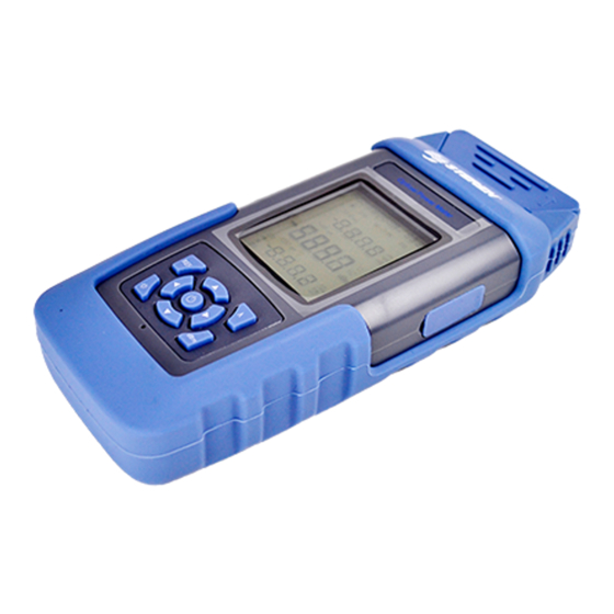
Page 6: Layout
BL-526-108 Optical Power Meter 4. Layout Signal Wavelength Logarithm Power Frequency light identification Linearity Power Battery Indicator Auto-OFF λ key REF key Power key Fig. 01... -
Page 7: Operation
BL-526-108 Optical Power Meter 5. Operation 1. Turn On / Turn Off • Press and hold the button for 3 seconds to turn on the Optical Power Meter. The Home display will appear as shown below. (Fig. 02) Fig. 02 Auto-OFF •... - Page 8 BL-526-108 Optical Power Meter 2. dBm Button • Press the dBm button to show absolute optical power measurement value. • While press the REF button to set the reference value, press the dBm button shortly to clear the reference value.
- Page 9 BL-526-108 Optical Power Meter 6. 270, 330, 1K, 2KHz Frequency Light Identification • Press and hold the λ button for 3 seconds to activate auto mode. • When the entering light is 270, 330, 1K & 2KHz modulated light, the meter identifies the frequency automatically and shows it on the LCD.
- Page 10 BL-526-108 Optical Power Meter 7. Automatic wavelength identification • Works with the laser light source to automatically identify wavelength from the source. 8. VFL Function • ▲ Press button shortly to output continuous light ▲ source; press button again to output pulse light source;...
- Page 11 BL-526-108 Optical Power Meter • Time Setting mode will exit automatically if left idle for 10 seconds. 10. Save Record • Short press the ◄ button to enter into the record storage interface. The record number for storing will be displayed on the screen. (Fig. 05) •...
- Page 12 BL-526-108 Optical Power Meter 11. Browse Record • Press ► shortly to enter into the record browse interface; browse records using the ◄ and ► buttons. • Press λ shortly to delete the current record. • Press shortly to exit.
-
Page 13: Maintenance
BL-526-108 Optical Power Meter 6. Maintenance • It is important to keep the sensor surface clean. Do not use dirty or non-standard adapters; do not insert a poorly polished connector into the port, otherwise it will damage the sensor end. - Page 14 BL-526-108 Optical Power Meter Safety Take appropriate eye-safe precautions when handling live fiber. Avoid condensation • This instrument is resistant to normal dust and moisture; however, it is not waterproof. • If moisture gets into the instrument, remove the battery and dry out the meter for at least one hour...
-
Page 15: Troubleshooting
BL-526-108 Optical Power Meter 7. Troubleshooting Issue Reason Solution LCD display is Low voltage Charge or dark replace battery. Sensor’s surface is Test result = Clean sensor. error dirty. Charge or Low voltage. replace battery. No display when The battery is under... - Page 16 BL-526-108 Optical Power Meter 8. Appendix A Testing Loss of Installed Fiber Optic Cable Plant 1) Test Diagram Fig. 07 2) Test Procedure • Clean all connectors and mating adapters. • Turn on equipment and allow time to warm-up. •...
- Page 17 BL-526-108 Optical Power Meter Fig. 08 Fig. 09...
- Page 18 BL-526-108 Optical Power Meter Fig. 10 9. Appendix B Testing Loss of Fiber Optic Cables, Single-Ended 1) Test Diagram Fig. 11...
- Page 19 BL-526-108 Optical Power Meter 2) Test Procedure • Clean all connectors and mating adapters. • Turn on equipment and allow time to warm-up. • Attach launch cable to source. This should remain connected to source for the duration of the test.
- Page 20 BL-526-108 Optical Power Meter 10. Appendix C Measuring Optical Power in Fiber Optic Systems 1) Test Diagram Fig. 13 2) Test Procedure • Clean all connectors and mating adapters. • Turn on equipment and allow time to warm-up • Set meter to wavelength of source and “dBm” to measure calibrated optical power meter.
- Page 21 BL-526-108 Optical Power Meter receiver power, disconnect the system cable that is connected to the receiver, and attach it to the power meter to measure.
-
Page 22: Management Software
BL-526-108 Optical Power Meter 11. Management Software About this software: The Management Software is used for data reading, function setup, and test file analysis, as well as management of the optical power meter. Software User Guide Contents: I. Installation of Optical Power Meter management software. - Page 23 BL-526-108 Optical Power Meter The main interface of the management software should display as below: Fig. 14...
- Page 24 BL-526-108 Optical Power Meter . Installation Double-click the installation icon Optical Power Meter management software V1.0 setup.exe to install the software. After successful installation, there will be a shortcut icon on the desktop. The user manual is mainly used to describe “Optical Power Meter management software V1.0.exe”.
- Page 25 BL-526-108 Optical Power Meter Fig. 15 2. Read: Read the parameters on meters History data – check Bit map of signal path in graphics mode Fig. 16...
- Page 26 BL-526-108 Optical Power Meter 3. Set: Set up parameters of meter through software Set clock – Set clock shown on meter display Fig. 17...
- Page 27 BL-526-108 Optical Power Meter 4. Help: Relevant menus about help Help – Show the on-line content for help About – About this software Fig. 18...
- Page 28 BL-526-108 Optical Power Meter III. Toolbar The management software toolbar appears as follows: Fig. 19 From left to right, the functions are: History data: Shows the historical testing results in the power meter Delete single item: Deletes a selected history testing data Delete all: Deletes all history testing data Set clock: Calibrates the power meter’s clock...
- Page 29 BL-526-108 Optical Power Meter Various Connection Status Images: Original Status: Successful Connection: Failed Connection:...
- Page 30 BL-526-108 Optical Power Meter IV. Operating Procedures 1. Launching software • After installation, Click Start->Program->"Optical Power Meter management software v1.0.exe" from the computer or click the shortcut icon on the computer desktop to launch the software. • Note: When starting the software for the first time, it should install the driver program automatically.
- Page 31 BL-526-108 Optical Power Meter status appears as , the connection is unsuccessful. Check the connection between the meter and computer, and / or whether the driver of the power meter has been installed. Then, continue attempting to connect until the status shows .
- Page 32 BL-526-108 Optical Power Meter 3. Read history data The Optical Power Meter can store up to 1000 groups of history testing records. Testing records can conveniently be uploaded to a computer for analysis and storage. • Connect the meter to a PC, then click” File->read history data”, or click the...
- Page 33 BL-526-108 Optical Power Meter After reading the history data, click in the toolbar to store the data. To edit or add notes to the data, double-click column “No." and "Description." A maximum of 10 alpha-numeric characters per column may be input into the “No.”...
- Page 34 BL-526-108 Optical Power Meter 5. Delete All To delete all history testing data: • Connect meter with PC and download the history testing data to computer. Click “read→ Delete All” or click the button to delete all the history testing data.
- Page 35 BL-526-108 Optical Power Meter • Click the “OK” button to set the clock; clicking the “Cancel” button will close the dialog box. 7. Save data Data read by the software can be stored in a computer for future analysis and management: •...
- Page 36 BL-526-108 Optical Power Meter 9. Export files Data files from the management software may be exported in ".xls or .cvs" file formats: • After reading or opening the desired file(s), click "File →Export" or click the button. • The program then shows the export file dialog box.
- Page 37 BL-526-108 Optical Power Meter 10. Print To print the read data: • After reading or opening files, click "File →Export" or click the button.
- Page 38 BL-526-108 Optical Power Meter . Software Troubleshooting Issue Reason and analysis Solution 1. Please check the physical 1. Physical connection between the connection is not computer and the optical power Clicking good. meter. “Connecting 2. The power meter 2. Check whether the power Equipment”...
- Page 39 BL-526-108 Optical Power Meter 12. Appendix D Notes on Connecting Equipment The connection of the meter is the first step to using the management software. Prior to using the software and clicking the “Connection of Equipment” button on the toolbar, please ensure the following: •...
- Page 40 BL-526-108 Optical Power Meter • When the “Link Status” in the toolbar turns green, it means connection is successful, and the user can perform other operations. • If “Link Status” is red, the connection has failed. Please check the physical connection of the drive installation until “Link Status”...
Need help?
Do you have a question about the BL-526-108 and is the answer not in the manual?
Questions and answers