
Related Manuals for Steren WIAT Wireless Display Tester


Summary of Contents for Steren WIAT Wireless Display Tester
- Page 1 WIRELESS Display Tester User Manual BL-526-106 Rev-03 Copyright © 2019 Steren Electronics Int’l, LLC. All rights reserved...
-
Page 3: Table Of Contents
Table of Contents Introduction Features P2-P3 Buttons Function Introduction P4-P5 Operating Instructions P6-P28 1.0. Power On 2.0. Standby Mode 3.0. Wake Up 4.0. Power Off 5.0. Introduction of the Basic Interface 5.1. Interface of Power On P6-P7 5.2. Interface of Menu 5.3. -
Page 4: Introduction P2
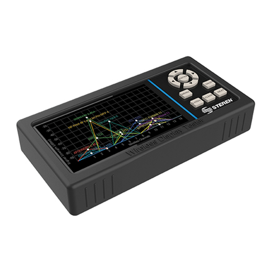
Introduction The Steren Wireless Display Tester (WDT) is a portable Wi-Fi signal testing device that is designed to aid field technicians in the testing of Wi-Fi device signal quality. It also assists in analyzing installation issues and in troubleshooting residential and small / medium business (SMB) wireless networks. - Page 5 • Roughly measures the distance between the Wi-Fi device and WDT (precision dependent on the environment). • Checks the data quantity of Wi-Fi device channels, signal strength, Time Graph of AP, APs quantity etc. • Indicates signal information without interference with a color-coded indication of Bad, Fair, or Good status for AP (Access Point) signal strength.
-
Page 6: Buttons Function Introduction
Buttons Function Introduction Fig. 1 Unit outline view Note: This device should be stored in a cool, dry area. During extended periods of non-use, the device should be charged once every 3 months. If the device cannot be turned on due to low battery, charge for 3.5 - 4.5 hours or until battery is fully charged. - Page 7 Buttons Function “Up” button, move to up selection. “Down” button, move to down selection. “Left” button, move to left selection. “Right” button, move to right selection. “ENTER” button, select item. “ON/OFF” button, power on or off the device. “MENU” button, show the function of menu. “2.4/5Ghz”...
-
Page 8: Operating Instructions
Operating Instructions 1.0. Power On Press and hold the “ON/OFF” button for 3 seconds to power on the unit. 2.0. Standby Mode Shortly press the “ON/OFF” button to go to standby mode. Note: Green LED blinks during standby mode. 3.0. Wake Up Shortly press the “ON/OFF”... -
Page 9: Interface Of Menu
Fig. 3 The loading screen 5.2. Interface of Menu Operating Instructions: Press “MENU” button, the menu list pops up on the left side of the screen. Press again, the menu list hides. Press “Up” and “Down” buttons to select the target function and then press the “ENTER”... - Page 10 Function: On the 2.4GHz to 5GHz Wireless band, the graph of the discovered Wireless network will be displayed. Each channel is 22MHz wide and the channels can overlap and interfere with each other. Channel 14 will not overlap with channel 1, 6, 11 and generally represent the best alignment.
-
Page 11: 5Ghz Bandwidth Channel Graph
Fig. 5 2.4GHz Bandwidth Channel Graph 5.3.2. 5GHz Bandwidth Channel Graph Function: The 5GHz channel graph will show a graphical representation of the Wireless network found on the 5.15GHz to 5.835GHz Wireless band. Each channel is 20MHz, 40MHz or 80MHz wide. Operating Instructions: a. - Page 12 2) The graphic of vertical coordinates can be auto-scaled based on the Signal strength. 3) The symbol “^” in the headline e.g. 36^64 means the Wireless channels signal exist in these channels range. Refer to Fig. 6 and Fig. 8. The symbol “-” e.g. 100-144 means no Wireless channels signal (less than -90dBm) in these channels range.
- Page 13 Fig. 8 5GHz Bandwidth Channel Graph CH149-CH165 channel * Explanation: Above picture Fig. 8, an AP named “JM 5G 153(155)”, the “JM 5G” is the APs SSID’s name, the 153(155) is the APs channel. The channel number display depends on the router setting, for example: 1) If channel setting is “153”, Bandwidth setting is 80MHz, then you will see the APs channel display 153(155).
-
Page 14: Channel Occupancy Interface P12
Fig. 10 Router bandwidth settings Fig. 11 5GHz Wi-Fi signal channel distribution map 5.4. Channel Occupancy Interface 5.4.1. 2.4GHz Bandwidth Channel Occupancy Function: The 2.4GHz bandwidth channel occupancy interface will clearly show the stacking of Wireless networks found on the 2.4GHz to 2.5GHz Wireless band channel. -
Page 15: Ghz Bandwidth Channel Occupancy
b. 2.4GHz Channel occupancy of 2.4GHz and 5GHz can be switched by pressing the “2.4/5Ghz” button. c. Press the “ENTER” button to run or pause the channel scanning function. When the device is in run mode, the icon is shown, when it’s in pause mode, the icon is shown. - Page 16 c. Press the “NEXT” button to check the occupancy of CH36- CH64, CH100-CH144, CH149-CH165. Refer to Fig. 13 and Note: The symbol “^” in the headline e.g. 36^64 means the Wireless channels signal exist in these channels range. Refer to Fig. 6 and Fig. 8. The symbol “-” e.g. 100-144 means no Wireless channels in these channels range and displays “No Signal”...
-
Page 17: Interface Of Time Graph
Fig. 15 5GHz Bandwidth Channel Occupancy CH149-CH165 Channel 5.5. Interface of Time Graph Function: The time graph mainly shows the variations of wireless network signal intensity with scanning time. Operating Instructions: a. Press the “MENU” button, the menu list pops up on the left side of the screen, select “Time Graph”... - Page 18 Fig. 16 2.4GHz Bandwidth Time Graph Fig. 17 5GHz Bandwidth Time Graph Fig. 18 The smoother curve of the time graph...
-
Page 19: Channel Rating
5.6. Channel Rating Function: Channel Rating shows the quality of wireless network channel. The more points present, the better channel quality is. Green indicates the best channel quality, yellow indicates fair channel quality, red indicates poor channel quality, and grey indicates the lost rating scores. -
Page 20: Interface Of Access Points (Ap) List
Fig. 20 5GHz bandwidth Channel Rating 5.7. Interface of Access Points (AP) List Function: Access Points (AP) list shows the SSID, frequency and channel of the wireless access point (WAP), MAC address and signal security configuration such as WPA, WPA2, distance between the wireless access point and the tester. -
Page 21: Interface Of Signal Meter
Fig. 21 Interface of Access Points Fig. 22 Interface of Access Points No Signal screen 5.8. Interface of Signal Meter Function: Signal Meter indicates the signal intensity of the wireless network. It shows the signal strength through the sound frequency of built-in speaker and visual meter scale (-100 to 0 dBm). -
Page 22: Setting Interface
Operating Instructions: a. Press the “MENU” button, the menu list pops up on the left side of the screen, select “Signal Meter” and press “ENTER” button, see Fig. 23. b. While the AP is scanned, press “Up” or “Down” button to check more of APs on the list. - Page 23 Operating Instructions: a. Press “MENU” button, the menu list pops up on the left side of the screen, select “Settings” and press “ENTER” button. b. Press “Up” or “Down” buttons to select target setting. c. Select “Scan interval”, then click “ENTER” button to set scan interval.
- Page 24 Fig. 24 Interface of Scan Interval Settings Fig. 25 Interface of Signal Range Settings Fig. 26 Interface of Wireless Connection...
- Page 25 Fig. 27 Interface of Brightness Adjustment Fig. 28 Interface of automatic Sleep Mode Fig. 29 Interface of Language settings...
-
Page 26: Interface Of About P24
Fig. 30 Interface of Factory reset 6.0. Interface of About Function: 1. About product information & version introduction. Refer to Fig.31 2. Check if there is new version to be upgraded. Operating Instructions: While you are connected to the internet, the updated software will automatically pop up. -
Page 27: Battery Icon And Led Indication
6.1. Battery Icon and LED Indication General Information: 1. The green LED on the top left of the buttons panel. 1.1. State 1, when the LED blinks slowly, the device is in sleep mode. 1.2. State 2, when the LED flashes, the device is being charged. 1.3. - Page 28 b. Press and hold the “ON/OFF” button for 3s and select “OK” to power off the device, if you plug in the USB cable with AC Adaptor (Note: ensure the AC Adaptor with voltage output) to charge the device, the battery icon will appear and is present for 5s to 7s then disappear and the green LED starts to flash.
- Page 29 Fig. 35 The battery icon displays during power off charging mode Fig. 36 Empty battery warning icon Fig. 37 Fully charge battery icon during power off mode...
- Page 30 Fig. 38 Charging the device using the provided Micro USB Cable and AC adapter.
- Page 32 Printed in China...
Need help?
Do you have a question about the WIAT Wireless Display Tester and is the answer not in the manual?
Questions and answers