Advertisement

2021/02/10 22:25:21 (GMT+09:00)
SERVICE MANUAL
Conditions of Use:
(1)
Please use this information only for the purpose of performing repair, maintenance and/or confi guration services of the Sony products (hereinafter the "Repair services") under the ser-
vice agreement entered into with the Sony group company (hereinafter the "Service agreement"). Using this information for any purpose other than the purpose described foregoing is
forbidden.
(2)
Only the Authorized Servicer's offi cers, employees or subcontractors (including their offi cers and employees) whose duties justify a need-to-know and who have agreed to hold
confi dential this information (collectively hereinafter the "Permitted users") are permitted to access and use this information. To disclose or disseminate to any person other than the
Permitted users is forbidden.
(3)
Destroy or erase any and all portion of this information promptly in an irrecoverable and secure fashion after achieving the purpose described in Section (1) above.
(4)
Do not copy, replicate, reproduce, alter, translate, transmit, sell, lease, or distribute this information in whole or in part without the prior written permission of the author.
(Notwithstanding foregoing, it is permitted to copy and distribute this information to the Permitted users.)
(5)
Please notify immediately any leakage, loss, theft, misappropriation, or other misuse of this information by e-mail to the following address:
somk-gcs-tissnexim-adm@jp.sony.com
(6)
In addition to the above, the terms and conditions of the Service agreement shall be applied to using this information.
Revision of Information:
This information may be changed or updated at any time without any prior notice. Please confi rm that this information is up-to-date before using it.
Note:
Be sure to keep your PC used for service and
checking of this unit always updated with the
latest version of your anti-virus software.
In case a virus aff ected unit was found during
service, contact your Service Headquarters.
Sony CONFIDENTIAL
For Authorized Servicer
9-896-642-05
2021B33-1
©
2021.02
Sony Home Entertainment &
Sound Products Inc.
HT-S20R
SA-WS20R/SS-S20R/SS20R
SYS SET

Advertisement

Table of Contents
loading

Summary of Contents for Sony HT-S20R

  • Page 1 Conditions of Use: Please use this information only for the purpose of performing repair, maintenance and/or confi guration services of the Sony products (hereinafter the “Repair services”) under the ser- vice agreement entered into with the Sony group company (hereinafter the “Service agreement”). Using this information for any purpose other than the purpose described foregoing is forbidden.
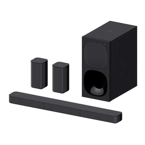
  • Page 2 E Model Photo: SS-SS20R (L-ch/R-ch) Photo: SS-S20R • All of the units included in the HT-S20R (SA-WS20R/SS-S20R/SS20R/ Remote control) are required to confi rming operation of this unit. Check in advance that you have all of the units and accessories.
  • Page 3: Table Of Contents

    2-6. Front Panel Block-1 (SA-WS20R) ........12 registered trademarks owned by Bluetooth SIG, 2-7. Front Panel Block-2 (SA-WS20R) ........13 Inc. and any use of such marks by Sony 2-8. USB Board, DISPLAY Board (SA-WS20R) ..... 14 Corporation is under license. Other trademarks 2-9.
  • Page 4: Servicing Notes

    ADVANCE PREPARATION WHEN CONFIRMING OPER- ATION – MAIN Board (Component Side) – All of the units included in the HT-S20R (SA-WS20R/SS-S20R/ SS20R/Remote control) are required to confi rming operation of this unit. Check in advance that you have all of the units and accessories.
  • Page 5 Parts for Chinese production (Type C) and parts for Vietnam produc- tion (Type V) are compatible. Therefore, it is no problem which type of parts is used. When distinguishing the type of HT-S20R to be repaired, refer to “MODEL IDENTIFICATION” on the following, and check the con- 5-011-763-01 tents of model number label.
  • Page 6 NOTE OF REPLACING THE ELECTRICAL PARTS ON struction manual of Bluetooth device. EACH BOARD FOR REPAIRING 4. Select the “HT-S20R” from the list searched by the Bluetooth Among mounted electrical parts on each board, only parts that are device and connect.
  • Page 7: Disassembly

    2021/02/10 22:25:21 (GMT+09:00) HT-S20R Sony CONFIDENTIAL Ver. 1.3 SECTION 2 For Authorized Servicer DISASSEMBLY • This set can be disassembled in the order shown below. 2-1. DISASSEMBLY FLOW (SA-WS20R/SS-S20R) • JIG SA-WS20R (SUBWOOFER) When disassembling the unit, use the following jig for speaker removal.
  • Page 8: Amp Block (Sa-Ws20R)

    2021/02/10 22:25:21 (GMT+09:00) HT-S20R Sony CONFIDENTIAL For Authorized Servicer Note: Follow the disassembly procedure in the numerical order given. 2-2. AMP BLOCK (SA-WS20R) Note 1: When removing the AMP block, removing the four top side top side 1 seven tapping screws (3.5 1 seven tapping screws (3.5...
  • Page 9: Main Board (Sa-Ws20R)

    2021/02/10 22:25:21 (GMT+09:00) HT-S20R Sony CONFIDENTIAL For Authorized Servicer 2-3. MAIN BOARD (SA-WS20R) top side AMP block rear side Caulking is top side – – upward. 3 ground wire FFC cable terminal assy MAIN board 2 screw MAIN board (BTP3 Caulking is downward.
  • Page 10: Power Board (Sa-Ws20R)

    2021/02/10 22:25:21 (GMT+09:00) HT-S20R Sony CONFIDENTIAL For Authorized Servicer 2-4. POWER BOARD (SA-WS20R) top side AMP block rear side 1 two screws (BTP3 2 Peel the POWER board block off of the cushion. cushion boss 1 three screws (BTP3 boss bottom side...
  • Page 11: Bt Module (Sa-Ws20R)

    2021/02/10 22:25:21 (GMT+09:00) HT-S20R Sony CONFIDENTIAL For Authorized Servicer 2-5. BT MODULE (SA-WS20R) Note 1: When the BT module is replaced, refer to “BLUETOOTH CONNECTION METHOD” on page 6. Caulking is Caulking is upward. downward. top side AMP block rear side 5 BT module (See Note 1)
  • Page 12: Front Panel Block-1 (Sa-Ws20R)

    2021/02/10 22:25:21 (GMT+09:00) HT-S20R Sony CONFIDENTIAL For Authorized Servicer 2-6. FRONT PANEL BLOCK-1 (SA-WS20R) • Continued on 2-7 (page 13). 1 Insert a flat-head screwdriver into the two slits on the bottom of the unit, and open a gap between the front panel block and speaker cabinet.
  • Page 13: Front Panel Block-2 (Sa-Ws20R)

    2021/02/10 22:25:21 (GMT+09:00) HT-S20R Sony CONFIDENTIAL For Authorized Servicer 2-7. FRONT PANEL BLOCK-2 (SA-WS20R) top side 1 Open the front panel block in the direction of the arrow. left side front panel block front side bottom side 5 front panel block soft cloth, etc.
  • Page 14: Usb Board, Display Board (Sa-Ws20R)

    2021/02/10 22:25:21 (GMT+09:00) HT-S20R Sony CONFIDENTIAL For Authorized Servicer 2-8. USB BOARD, DISPLAY BOARD (SA-WS20R) 1 two screws 2 USB board (PTP2.5 Note 2: When installing the USB board, align the two holes and two bosses. hole hole soft cloth, etc. top side...
  • Page 15: Front Panel Assy, Touch Key Board (Sa-Ws20R)

    2021/02/10 22:25:21 (GMT+09:00) HT-S20R Sony CONFIDENTIAL For Authorized Servicer 2-9. FRONT PANEL ASSY, TOUCH KEY BOARD (SA-WS20R) Note about installing the TOUCH KEY board block top side front panel assy Slant. Gap. – Inner view – TOUCH KEY board block 1 Peel the TOUCH KEY board block 4 double tape off of the front panel assy.
  • Page 16: Spk Unit (Subwoofer), Wood Box Assy (Sa-Ws20R)

    2021/02/10 22:25:21 (GMT+09:00) HT-S20R Sony CONFIDENTIAL Ver. 1.3 For Authorized Servicer 2-10. SPK UNIT (SUBWOOFER), WOOD BOX ASSY (SA-WS20R) 1 four screws • Installation direction for the SPK unit (BVTP4 Note 1: When installing the SPK unit, make the position of terminals as shown in the figure below.
  • Page 17: Speaker Block-1 (Ss-S20R)

    2021/02/10 22:25:21 (GMT+09:00) HT-S20R Sony CONFIDENTIAL For Authorized Servicer 2-11. SPEAKER BLOCK-1 (SS-S20R) • Continued on 2-12 (page 18). Note 1: The left side, center and right side of speaker block can be removed using the same procedure. This explanation uses illustrations from the left side.
  • Page 18: Speaker Block-2 (Ss-S20R)

    2021/02/10 22:25:21 (GMT+09:00) HT-S20R Sony CONFIDENTIAL For Authorized Servicer 2-12. SPEAKER BLOCK-2 (SS-S20R) Note 1: The left side, center and right side of speaker block can be removed using 1 Insert a flat-head screwdriver into the gap the same procedure. This explanation uses illustrations from the left side.
  • Page 19: Grille Assy_L (Left Side) (Ss-S20R)

    2021/02/10 22:25:21 (GMT+09:00) HT-S20R Sony CONFIDENTIAL For Authorized Servicer 2-13. GRILLE ASSY_L (LEFT SIDE) (SS-S20R) 1 two screws (BTP3 2 claw 1 three screws (BTP3 2 claw 2 claw 2 claw 2 claw 1 two screws speaker block (BTP3 (left side) 2 claw...
  • Page 20: Grille Assy_R (Right Side) (Ss-S20R)

    2021/02/10 22:25:21 (GMT+09:00) HT-S20R Sony CONFIDENTIAL For Authorized Servicer 2-15. GRILLE ASSY_R (RIGHT SIDE) (SS-S20R) 2 claw 1 five screws (BTP3 2 claw 2 claw 2 claw 2 claw speaker block 1 five screws (right side) (BTP3 2 claw 4 grille assy_R (right side) 2-16.
  • Page 21: Rubber Foot, Cushion Foot, Rear Panel Block (Ss-S20R)

    2021/02/10 22:25:21 (GMT+09:00) HT-S20R Sony CONFIDENTIAL For Authorized Servicer 2-17. RUBBER FOOT, CUSHION FOOT, REAR PANEL BLOCK (SS-S20R) 3 cushion foot 3 cushion foot 1 model number label left side bottom side 2 rubber foot 4 rear panel block rear side 3 cushion...
  • Page 22: Troubleshooting

    2021/02/10 22:25:21 (GMT+09:00) HT-S20R Sony CONFIDENTIAL SECTION 3 For Authorized Servicer TROUBLESHOOTING 1. Starting up (SA-WS20R) “HELLO” is displayed in the front panel The cable of 9 pin connecting the display when the AC power cord is POWER board and the MAIN board is Insert the cable into the correct position.
  • Page 23 2021/02/10 22:25:21 (GMT+09:00) HT-S20R Sony CONFIDENTIAL For Authorized Servicer 3. Check the audio output (SA-WS20R) The stereo mini cable is inserted properly The sound of the “ANALOG” function is Insert the stereo mini cable into the into the ANALOG IN jack (JK300) on the output normally.
  • Page 24: Diagrams

    2021/02/10 22:25:21 (GMT+09:00) HT-S20R Sony CONFIDENTIAL SECTION 4 For Authorized Servicer DIAGRAMS 4-1. BLOCK DIAGRAM BT Internal Antenna Flash IC201 To CN200 TX+/TX- 16Mbit HDMI Out BT Module JK201 WB116A(EX3) BT UART control & Reset AB1520 SPIDF-IN(BT OUT) 18PIN P0.5 FFC SPK_OUT (BTL)
  • Page 25 2021/02/10 22:25:21 (GMT+09:00) HT-S20R Sony CONFIDENTIAL For Authorized Servicer THIS NOTE IS COMMON FOR PRINTED WIRING BOARDS AND SCHEMATIC DIAGRAMS. (In addition to this, the necessary note is printed in each block.) For Printed Wiring Boards. For Schematic Diagrams. Note: Note: • All capacitors are in μF unless otherwise noted. (p: pF) •...
  • Page 26: Printed Wiring Board - Main Board (Sa-Ws20R)

    2021/02/10 22:25:21 (GMT+09:00) HT-S20R Sony CONFIDENTIAL Ver. 1.2 For Authorized Servicer 4-2. PRINTED WIRING BOARD - MAIN Board (SA-WS20R) - • See page 25 for Circuit Boards Location. • : Uses unleaded solder. MAIN BOARD MAIN BOARD (COMPONENT SIDE) (CONDUCTOR SIDE) Note: When the IC501, IC502, IC503 on the MAIN board, or the complete MAIN board is replaced with a new part, spread the compound for heat radiation to the touching portion between the IC501, IC502, IC503 on the MAIN board and the heatsink.
  • Page 27: Main Board (1/2) (Sa-Ws20R)

    2021/02/10 22:25:21 (GMT+09:00) HT-S20R Sony CONFIDENTIAL For Authorized Servicer 4-3. SCHEMATIC DIAGRAM - MAIN Board (1/2) (SA-WS20R) - • See page 34 for IC Block Diagrams. • See page 36 for IC Pin Function Description. MAIN BOARD (1/2) SUB 60W 30% 4 OHM...
  • Page 28: Main Board (2/2) (Sa-Ws20R)

    2021/02/10 22:25:21 (GMT+09:00) HT-S20R Sony CONFIDENTIAL For Authorized Servicer 4-4. SCHEMATIC DIAGRAM - MAIN Board (2/2) (SA-WS20R) - MAIN BOARD (2/2) CN200 C365 0.5mm/18pin JK300 IC303 PCM1808 BL_3.3V IC202 WB6332 BK5.2V C354 10U/10V TP201 TP300 C350 10U/10V BT_SDA MP3R FB304 R314 MP3_R...
  • Page 29: Printed Wiring Board - Usb Board (Sa-Ws20R)

    2021/02/10 22:25:21 (GMT+09:00) HT-S20R Sony CONFIDENTIAL For Authorized Servicer 4-5. PRINTED WIRING BOARD - USB Board (SA-WS20R) - • See page 25 for Circuit Boards Location. • : Uses unleaded solder. USB BOARD (COMPONENT SIDE) USB BOARD (CONDUCTOR SIDE) 4-6. SCHEMATIC DIAGRAM - USB Board (SA-WS20R) -...
  • Page 30: Printed Wiring Board - Display Board (Sa-Ws20R)

    2021/02/10 22:25:21 (GMT+09:00) HT-S20R Sony CONFIDENTIAL For Authorized Servicer 4-7. PRINTED WIRING BOARD - DISPLAY Board (SA-WS20R) - • See page 25 for Circuit Boards Location. • : Uses unleaded solder. DISPLAY BOARD (COMPONENT SIDE) DISPLAY BOARD (CONDUCTOR SIDE) 4-8. SCHEMATIC DIAGRAM - DISPLAY Board (SA-WS20R) -...
  • Page 31: Printed Wiring Board - Touch Key Board (Sa-Ws20R)

    2021/02/10 22:25:21 (GMT+09:00) HT-S20R Sony CONFIDENTIAL For Authorized Servicer 4-9. PRINTED WIRING BOARD - TOUCH KEY Board (SA-WS20R) - • See page 25 for Circuit Boards Location. • : Uses unleaded solder. TOUCH KEY BOARD (SIDE A) TOUCH KEY BOARD (SIDE B) 4-10.
  • Page 32: Printed Wiring Board - Power Board (Sa-Ws20R)

    2021/02/10 22:25:21 (GMT+09:00) HT-S20R Sony CONFIDENTIAL For Authorized Servicer 4-11. PRINTED WIRING BOARD - POWER Board (SA-WS20R) - • See page 25 for Circuit Boards Location. • : Uses unleaded solder. POWER BOARD (COMPONENT SIDE) POWER BOARD (CONDUCTOR SIDE) HT-S20R SYS SET...
  • Page 33: Schematic Diagram - Power Board (Sa-Ws20R)

    2021/02/10 22:25:21 (GMT+09:00) HT-S20R Sony CONFIDENTIAL For Authorized Servicer 4-12. SCHEMATIC DIAGRAM - POWER Board (SA-WS20R) - POWER BOARD R940 100 ohm*5 C934 102-500V C902 R941 BK22V R942 220p-400V R944 R945 L-6UH C905 CN901 100P 1KV BK21.5V C915 L903 CN9P-25 C906 TP904...
  • Page 34 2021/02/10 22:25:21 (GMT+09:00) HT-S20R Sony CONFIDENTIAL For Authorized Servicer • IC Block Diagrams – MAIN Board – IC500 TAS5538 Output Control 2 Crossbar Mixer 8 Crossbar Mixer AVSS AVDD DVSS DVDD DAP Control PWM Control VR_PWM VR_ANA VBGAP System Control AVDD_REF VR_DIG Clock, PLL, and Serial Data I/F SYS SET...
  • Page 35 2021/02/10 22:25:21 (GMT+09:00) HT-S20R Sony CONFIDENTIAL For Authorized Servicer IC501 – 503 TAS5614LA /CLIP /OTW /FAULT BST_X GVDD_X AVDD DVDD /RESET MODE1-3 POWER-UP RESET AVDD AVDD TEMP SENSE DVDD CB3C OVER- DVDD LOAD PROTECTION STARTUP CONTROL C_START BST_A PVDD_AB INPUT_A PWM &...
  • Page 36 2021/02/10 22:25:21 (GMT+09:00) HT-S20R Sony CONFIDENTIAL For Authorized Servicer • IC Pin Function Description MAIN BOARD IC304 MT8307OQE (AUDIO DSP, DOLBY DIGITAL SURROUND) Pin No. Pin Name Description AVDD12_2 Power supply terminal (+1.2V) (analog system) AVDD33_1 Power supply terminal (+3.3V) (analog system)
  • Page 37 2021/02/10 22:25:21 (GMT+09:00) HT-S20R Sony CONFIDENTIAL For Authorized Servicer Pin No. Pin Name Description 77 to 81 RA10, RA0 to RA3 Address signal output terminal for SD-RAM DVDD12 Power supply terminal (+1.2V) (digital system) SPDIF/GPIO12 HDMI +5V power on/off control signal output terminal...
  • Page 38: Exploded Views

    2021/02/10 22:25:21 (GMT+09:00) HT-S20R Sony CONFIDENTIAL Ver. 1.3 SECTION 5 For Authorized Servicer EXPLODED VIEWS Note: • -XX and -X mean standardized parts, so • The mechanical parts with no reference they may have some diff erence from the number in the exploded views are not sup- original one.
  • Page 39: Subwoofer Amp Section (Sa-Ws20R)

    2021/02/10 22:25:21 (GMT+09:00) HT-S20R Sony CONFIDENTIAL Ver. 1.4 For Authorized Servicer 5-2. SUBWOOFER AMP SECTION (SA-WS20R) (See Note 2) not supplied not supplied not supplied not supplied (See Note 1, 2, 3) FFC1 (model number label) (heatsink) supplied not supplied supplied not supplied...
  • Page 40: Bar Speaker Section (Ss-S20R)

    2021/02/10 22:25:21 (GMT+09:00) HT-S20R Sony CONFIDENTIAL Ver. 1.2 For Authorized Servicer 5-3. BAR SPEAKER SECTION (SS-S20R) not supplied (See Note) not supplied #3 #3 (model number label) (See Note) #4 #4 not supplied not supplied not supplied supplied (See Note) not supplied...
  • Page 41: Surround Speaker Section (Ss-Ss20R)

    2021/02/10 22:25:21 (GMT+09:00) HT-S20R Sony CONFIDENTIAL Ver. 1.2 For Authorized Servicer 5-4. SURROUND SPEAKER SECTION (SS-SS20R) – L-ch – – R-ch – Note: The production country has been changed from China to Vietnam in the midway of production. In this service manual, parts for Chinese production are described to as “Type C”...
  • Page 42: Electrical Parts List

    Parts for “Type C” and “Type V” are compatible. Therefore, it is no problem which type of parts is used. When distinguishing the type of HT-S20R, refer to “MODEL Note 3: When the BT module (Ref. No. BT1) is replaced, refer to “BLUE- IDENTIFICATION”...
  • Page 43: Accessories

    Parts for “Type C” and “Type V” are compatible. Therefore, it is no problem which type of parts is used. When distinguishing the type of HT-S20R, refer to “MODEL IDENTIFICATION” on page 5. In addition, it can also distinguish by referring to the Part No. or printing country (“Printed in China”...
  • Page 44 2021/02/10 22:25:21 (GMT+09:00) HT-S20R Sony CONFIDENTIAL Ver. 1.2 For Authorized Servicer Ref. No. Part No. Description Remark 149348511 REMOTE COMMANDER (RMT-AH412U) (Remote control) 930100365 AV CABLE (Stereo Mini cable) (IND) Remote control (1) 930100366 OPT CABLE (Optical digital cable) (AEP, UK, SP, AR, LA, AF)
  • Page 45 2021/02/10 22:25:21 (GMT+09:00) HT-S20R Sony CONFIDENTIAL For Authorized Servicer REVISION HISTORY Ver. Date Description of Revision 2019.12 2020.04 Addition of SP, AR and LA models Addition of “NOTE OF REPLACING THE FUSE” on SERVICING NOTES (SMR-20002) 2020.09 Change of Production Country from the China to the Vietnam (AEP, UK, IND, LA, AF) Deletion of Information for AUS model Correction of Ref.

This manual is also suitable for:

Sa-ws20rSs-s20rSs-ss20r

Table of Contents