Table of Contents
Advertisement
HCD-DH50R/DH70SWR
SERVICE MANUAL
Ver. 1.1 2009.07
• HCD-DH50R is the amplifi er, USB, disc player and
tuner section in CMT-DH50R.
• HCD-DH70SWR is the amplifi er, USB, disc player and
tuner section in CMT-DH70SWR.
• When the operation of the HCD-DH70SWR is con-
fi rmed, it is necessary to connect the SA-WDH70SWR.
Confi rm the HCD-DH70SWR and SA-WDH70SWR
are prepared beforehand when you repair.
•
This product incorporates copyright protection technol-
ogy that is protected by U.S. patents and other intellectual
property rights. Use of this copyright protection technol-
ogy must be authorized by Macrovision, and is intended
for home and other limited viewing uses only unless oth-
erwise authorized by Macrovision. Reverse engineering or
disassembly is prohibited.
•
This system incorporates Dolby1) Digital and DTS2)
Digital Surround System.
1) Manufactured under license from Dolby Laboratories.
"Dolby" and the double- D symbol are trademarks of
Dolby Laboratories.
2) Manufactured under license under U.S. Patent
#'s: 5,451,942; 5,956,674; 5,974,380; 5,978,762;
6,487,535 & other U.S. and worldwide patents issued
& pending. DTS and DTS 2.0 + Digital Out are regis-
tered trademarks and the DTS logos and Symbol are
trademarks of DTS, Inc. ©1996-2008 DTS, Inc. All
Rights Reserved.
•
"DVD+RW," "DVD-RW," "DVD+R," "DVD VIDEO,"
and the "CD" logos are trademarks.
•
DivX® is a video fi le compression technology, developed
by DivX, Inc. DivX, DivX Certifi ed, and associated logos
are trademarks of DivX, Inc. and are used under license.
This product is an offi cial DivX® certifi ed product.
•
MPEG Layer-3 audio coding technology and patents li-
censed from Fraunhofer IIS and Thomson.
•
This system incorporates High-Defi nition Multimedia In-
terface (HDMITM) technology. HDMI, the HDMI logo
and High-Defi nition Multimedia Interface are trademarks
or registered trademarks of HDMI Licensing LLC.
•
"BRAVIA" is a trademark of Sony Corporation.
•
Control for HDMI is a mutual control function standard
used by CEC (Consumer Electronics Control) for HDMI
(High-Defi nition Multimedia Interface).
•
Windows Media is a registered trademark of Microsoft
Corporation in the United States and/or other countries.
•
THIS PRODUCT IS LICENSED UNDER THE MPEG-
4 VISUAL PATENT PORTFOLIO LICENSE FOR THE
PERSONAL AND NON-COMMERCIAL USE OF A
CONSUMER FOR
(i) ENCODING VIDEO IN COMPLIANCE WITH THE
MPEG-4 VISUAL STANDARD ("MPEG-4 VIDEO")
AND/OR
(ii) DECODING MPEG-4 VIDEO THAT WAS ENCOD-
ED BY A CONSUMER ENGAGED IN A PERSONAL
AND NONCOMMERCIAL ACTIVITY AND/OR WAS
OBTAINED FROM A VIDEO PROVIDER LICENSED
BY MPEG LA TO PROVIDE MPEG-4 VIDEO.
NO LICENSE IS GRANTED OR SHALL BE IMPLIED
FOR ANY OTHER USE. ADDITIONAL INFORMA-
TION INCLUDING THAT RELATING TO PROMO-
TIONAL, INTERNAL AND COMMERCIAL USES
AND LICENSING MAY BE OBTAINED FROM MPEG
LA, LLC. SEE http://www.mpegla.com/
Sony Corporation
9-889-569-02
2009G05-1
Audio&Video Business Group
©
2009.07
Published by Sony Techno Create Corporation
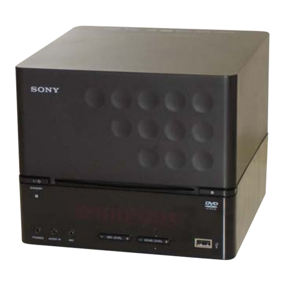
Photo: HCD-DH50R
Model Name Using Similar Mechanism
DVD Mechanism Type
Optical Pick-up Block Name
Amplifier section
HCD-DH70SWR
DIN power output (rated)
45 + 45 watts (5.5 ohms at 1 kHz,
DIN)
Continuous RMS power output (reference)
60 + 60 watts (5.5 ohms at 1 kHz, 10%
THD)
Music power output (reference):
60 + 60 watts (5.5 ohms at 1 kHz, 10%
THD)
HCD-DH50R
DIN power output (rated)
60 + 60 watts (4 ohms at 1 kHz, DIN)
Continuous RMS power output (reference)
80 + 80 watts (4 ohms at 1 kHz, 10%
THD)
Music power output (reference):
80 + 80 watts (4 ohms at 1 kHz, 10%
THD)
Inputs
TV/VIDEO AUDIO IN (phono jack):
voltage 450 mV/250 mV, impedance
47 kilohms
AUDIO IN (stereo mini jack):
voltage 700 mV, impedance
47 kilohms
MIC (mini jack):
sensitivity 0.8 mV, impedance
10 kilohms
Outputs
VIDEO OUT (phono jack):
max. output level 1 Vp-p, unbalanced,
Sync negative, load impedance
75 ohms
COMPONENT VIDEO OUT:
Y
: 1 Vp-p, 75 ohms
P
/C
: 0.7 V
p-p, 75 ohms
B
B
P
/C
: 0.7 V
p-p, 75 ohms
R
R
HDMI OUT: Type A (19 pins)
DIGITAL OUT OPTICAL (square optical
connector jack, rear panel):
Wavelength 660 nm
PHONES (stereo mini jack):
accepts headphones of 8 ohms or
more
AEP Model
HCD-DH50R/DH70SWR
Singapore Model
Taiwan Model
Korean Model
Thai Model
SPECIFICATIONS
FRONT SPEAKER
HCD-DH70SWR: Use only the
supplied speakers SS-CDH70SWR.
HCD-DH50R: Use only the supplied
speakers SS-CDH50R2 (only for
European and Russian models)/SS-
CDH50R (only for Asian models).
SUBWOOFER (HCD-DH70SWR only):
Use only the supplied subwoofer SA-
WDH70SWR.
USB section
Supported bit rate
MP3 (MPEG1 Audio Layer-3):
32 — 320 kbps
WMA: 48 — 192 kbps
AAC: 48 — 320 kbps
Sampling frequencies
MP3 (MPEG1 Audio Layer-3):
32/44.1/48 kHz
WMA: 44.1 kHz
AAC: 44.1 kHz
(USB) port:
Maximum current:
500 mA
Disc player section
System:
Compact disc and digital audio and
video system
Laser Diode Properties
Emission duration: Continuous
Laser Output*: Less than 1000μW
*
This output is the value measurement
at a distance of 200mm from the
objective lens surface on the Optical
Pick-up Block with 7mm aperture.
Frequency response
DVD (PCM 48 kHz): 2 Hz — 22 kHz
(±1 dB)
CD: 2 Hz — 20 kHz (±0.5 dB)
Video color system format
European and Russian models: PAL
Other models: NTSC and PAL
– Continued on next page –
DVD RECEIVER
HCD-DH50R
NEW
CDM86A-DVBU101
KHM-313CAB
Advertisement
Table of Contents

Related Manuals for Sony HCD-DH50R


Summary of Contents for Sony HCD-DH50R
- Page 1 Korean Model Ver. 1.1 2009.07 Thai Model HCD-DH50R • HCD-DH50R is the amplifi er, USB, disc player and tuner section in CMT-DH50R. • HCD-DH70SWR is the amplifi er, USB, disc player and tuner section in CMT-DH70SWR. • When the operation of the HCD-DH70SWR is con- fi...
- Page 2 87.5 — 108.0 MHz (50 kHz step) When the self-diagnosis function Although this is not a malfunction and Antenna: is activated to prevent the system for Sony service use only, normal system DivX FM lead antenna from malfunctioning, a 5-character File extension: .avi/.divx Antenna terminals: service number (e.g.
-
Page 3: Table Of Contents
HCD-DH50R/DH70SWR TABLE OF CONTENTS SERVICING NOTES 5-5. Printed Wiring Boards - DVD SERVO Section - ... 31 ..........5-6. Schematic Diagram - DVD SERVO Section (1/4) - ..32 5-7. Schematic Diagram - DVD SERVO Section (2/4) - ..33 DISASSEMBLY 5-8. -
Page 4: Servicing Notes
UNLEADED SOLDER Model Part No. Boards requiring use of unleaded solder are printed with the lead- HCD-DH50R: AEP 4-141-531-0[] free mark (LF) indicating the solder contains no lead. (Caution: Some printed circuit boards may not come printed with HCD-DH50R: Russian... - Page 5 HCD-DH50R/DH70SWR HOW TO EJECT THE DISC WHEN POWER SWITCH TURNS OFF • Please work after taking out DVD mechanism deck of the set. disc Turn the gear (IDL-B) to the direction of the arrow. DVD mechanism deck – Bottom view –...
- Page 6 HCD-DH50R/DH70SWR POW-SUPPLY BOARD SERVICE POSITION front side rear side POW-SUPPLY board MAIN BOARD SERVICE POSITION • Please connect following extension jig. Jig No. Part No. Cores Length (mm) J-2501-102-A J-2501-199-A J-2501-241-A J-2501-244-A Connect extension jig 4 to the MAIN board (CN503) and wire (flat type) (21 core).
- Page 7 HCD-DH50R/DH70SWR ARRANGEMENT OF POWER CORD power cord line filter coil (T1) 15 mm or more POW-SUPPLY board (bottom view) ARRANGEMENT OF WIRE ROD AND DC FAN LEAD WIRE Note 1: The wire rod must not leak to the board. Note 2: Bind CN702 from clamp filter and the wire rod of CN703 with clamp.
- Page 8 HCD-DH50R/DH70SWR Ver. 1.1 ARRANGEMENT OF FLEXIBLE FLAT CABLE flexible flat cable (5 core) front side hook flexible flat cable (25 core) flexible flat cable lead wire (11 core) (AEP), flexible flat cable flexible flat cable (11 core) (AEP), (21 core) (RU, SP, TW, KR, TH)
- Page 9 HCD-DH50R/DH70SWR ARRANGEMENT OF LEAD WIRE lead wire lead wire...
-
Page 10: Disassembly
HCD-DH50R/DH70SWR SECTION 2 DISASSEMBLY • This set can be disassembled in the order shown below. 2-1. DISASSEMBLY FLOW 2-2. BACK COVER, SIDE_L/R (Page 11) 2-3. TOUCH PANEL ASSY, TOP ASSY (Page 11) 2-4. DC FAN (M002) (Page 12) 2-5. POW-SUPPLY BOARD (Page 12) 2-6. -
Page 11: Back Cover, Side_L/R
HCD-DH50R/DH70SWR Note: Follow the disassembly procedure in the numerical order given. 2-2. BACK COVER, SIDE_L/R 7 cushion (10 3 screw (BVTP3 6 three claws 8 side_L 1 five screws (BVTP3 2 back cover 4 screw (BV3 3-CR) 7 three cushions (10... -
Page 12: Dc Fan (M002)
HCD-DH50R/DH70SWR 2-4. DC FAN (M002) 1 four screws (DH70SWR) (BV3 2 screw (BV/ring) 5 two screws (BVTP3 2 screw (BV/ ring) 1 three screws (BV3 6 rear cover 7 DC fan (M002) 4 DC fan connector (CN672) 2-5. POW-SUPPLY BOARD q;... -
Page 13: Front Panel Block
HCD-DH50R/DH70SWR 2-6. FRONT PANEL BLOCK 3 screw 4 terminal (BVTP2.6 3CR) 2 flexible flat cable (7 core) (CN510) 1 flexible flat cable (13 core) (CN511) 6 two claws 7 front panel block 5 two screws (BVTT3 2-7. SP-CONN BOARD Note: This illustration sees the set from rear side. -
Page 14: Main Board
HCD-DH50R/DH70SWR Ver. 1.1 2-8. MAIN BOARD Note: This illustration sees the set from rear side. • Abbreviation 7 flexible flat cable (11 core) qh heat sink (S-master) (AEP: CN505), : Korean model flexible flat cable (9 core) : Russian model... -
Page 15: Dvd Mechanism Deck (Cdm86A-Dvbu101)
HCD-DH50R/DH70SWR 2-10. DVD MECHANISM DECK (CDM86A-DVBU101) 3 Lift up the FFC holder. PRECAUTION WHEN REMOVING GOOD OPTICAL PICK-UP BLOCK 4 Be sure to bridge here, and then disconnect the wire (flat type) (24 core). 1 two claws (optical pick-up block will be destroyed 7 DVD mechanism deck without bridging.) -
Page 16: Chassis (Top)
HCD-DH50R/DH70SWR 2-12. CHASSIS (TOP) 4 three screws 1 screw (B2.6 (B2.6 3 two screws 2 lever (CL UP2) 5 chassis (top) 2-13. MS-214 BOARD 2 two screws (B2.6 5 MS-214 board 3 Remove two solders. 4 motor (pully) assy (loading) -
Page 17: Holder (Bu) Assy
HCD-DH50R/DH70SWR 2-14. HOLDER (BU) ASSY 1 screw (B2.6 2 lever (CL UP2) 6 holder (BU) assy 4 LHL support 5 floating screw (PTPWH M2.6) 3 two screws 5 floating screw (PTPWH M2.6) 2-15. LEVER (BU LOCK) Note: This illustration sees the mechanism deck from bottom side. -
Page 18: Close Lever
HCD-DH50R/DH70SWR 2-16. CLOSE LEVER Note: This illustration sees the mechanism deck from bottom side. 1 washer (3-1-0.4) 5 close lever 3 claw 2 SPR-E lever close 4 shaft disc stop 2-17. LEVER (DIR), GEAR (IDL-B) Note: This illustration sees the mechanism deck from bottom side. -
Page 19: Lever (Loading-L/R)
HCD-DH50R/DH70SWR 2-18. LEVER (LOADING-L/R) SPT-T (loading-R) SPR-T (loading-L) 5 lever (loading-R) 2 two hooks 4 two hooks 3 lever (loading-L) PRECAUTION DURING LEVER (LOADING R/L) INSTALLATION – Bottom view – Align the horizontal position. lever (loading-L) lever (loading-R) Install the both levers so that they move symmetrically. -
Page 20: Lever (Disc Sensor)/(Disc Stop)
HCD-DH50R/DH70SWR 2-19. LEVER (DISC SENSOR)/(DISC STOP) 1 gear (cap) 2 gear (IDL-L) PRECAUTION DURING DISC STOP LEVER INSTALLATION chassis (top) hole 5 two hooks 3 two claws lever (disc stop) 6 lever (disc stop) hole Install the lever (disc stop) so that the both holes 4 lever (disc sensor) are aligned. -
Page 21: Test Mode
HCD-DH50R/DH70SWR SECTION 3 TEST MODE COLD RESET TUNER STEP CHANGE Reset the system to its factory default settings. (Except AEP and Russian models only) Procedure: The step interval of AM channels can be toggled between 9 kHz 1. Press the [ ] button to turn on the system. - Page 22 HCD-DH50R/DH70SWR DVD VERSION VIEW DVD SECTION This mode is executed while connected with the TV monitor. The GENERAL DESCRIPTION DVD version is displayed in the TV monitor. The IOP measurement allows you to make diagnosis and adjust- Procedure: ment simply by using the remote commander and monitor TV. The 1.
- Page 23 HCD-DH50R/DH70SWR 2. Select “2. Drive Manual Operation” by pressing the [2] button 1-2. EMERGENCY HISTORY on the remote commander. The screen will appear as shown. To check the emergency history, please follow the following pro- cedure. 1. From the Top Menu of Remocon Diagnosis Menu, select “3.
- Page 24 HCD-DH50R/DH70SWR Spindle stop error 1-2-4. Return to the Top Menu of Remocon Diagnosis Focus on error Menu Seek fail error Press [0] button on the remote commander. Read Q data/ID error Lead in data read fail 1-3. CHECK VERSION INFORMATION...
-
Page 25: Electrical Check
HCD-DH50R/DH70SWR SECTION 4 ELECTRICAL CHECK FM TUNE LEVEL CHECK signal generator Procedure: 1. Turn on the set. 2. Input the following signal from signal generator to FM antenna input directly. Carrier frequency : A = 87.5 MHz, B = 98 MHz, C = 108 MHz... -
Page 26: Diagrams
HCD-DH50R/DH70SWR Ver. 1.1 SECTION 5 DIAGRAMS 5-1. BLOCK DIAGRAM - DVD SERVO Section - OPTICAL DIGITAL OUT SPDIF 215 TRANSMITTER OPTICAL IC651 DVDRF IP D/A CONVERTER VOA/A DVDA IC1002 VOB/B DVDB LOUT (Page 28) ASDATA0 226 SDTI L OUT 11... -
Page 27: Block Diagram - Video Section
HCD-DH50R/DH70SWR 5-2. BLOCK DIAGRAM - VIDEO Section - SD-RAM VIDEO AMP, 75Ω DRIVER IC2009 IC5001 J651 VIDEO R-ch is omitted due to same as L-ch. CVBS 187 CVBS IN CV OUT 30 VIDEO OUT SIGNAL PATH CV SAG 29 : AUDIO J652 DQ0 –... -
Page 28: Block Diagram - Audio Section
HCD-DH50R/DH70SWR Ver. 1.1 5-3. BLOCK DIAGRAM - AUDIO Section - (DH50R: RU, SP, TW, KR, TH/DH70SWR: RU) MIC SCORE DIGITAL ECHO R-ch is omitted due to same as L-ch. IC251 SIGNAL PATH (Page 26) MCO 21 : AUDIO J251 MIC AMP... -
Page 29: Block Diagram - Panel/Power Supply Section
HCD-DH50R/DH70SWR Ver. 1.1 5-4. BLOCK DIAGRAM - PANEL/POWER SUPPLY Section - +1.8V CPU +1.8V REGULATOR IC2004 D907 +3.3V +5.5V USB_OCD, SW +3.3V REGULATOR REGULATOR OVER CURRENT USB_SW USB_OCD IC6002 IC903 (Page 27) DETECT IC6001 USB +5V REGULATOR IC7004 USB_SW Q906... - Page 30 HCD-DH50R/DH70SWR Ver. 1.1 THIS NOTE IS COMMON FOR PRINTED WIRING BOARDS AND SCHEMATIC DIAGRAMS. • Circuit Boards Location (In addition to this, the necessary note is printed in each block.) POW-SUPPLY board For Printed Wiring Boards. For Schematic Diagrams. Note:...
-
Page 31: Printed Wiring Boards - Dvd Servo Section
HCD-DH50R/DH70SWR Ver. 1.1 5-5. PRINTED WIRING BOARDS - DVD SERVO Section - • See page 30 for Circuit Boards Location. • : Uses unleaded solder. DMB20 BOARD (COMPONENT SIDE) VIDEO-OUT (Page 40) DMB20 BOARD (CONDUCTOR SIDE) BOARD CN652 CL2027 CN2006... -
Page 32: Schematic Diagram - Dvd Servo Section (1/4)
HCD-DH50R/DH70SWR Ver. 1.1 5-6. SCHEMATIC DIAGRAM - DVD SERVO Section (1/4) - • See page 45 for Waveforms. • See page 48 for IC Block Diagrams. • See page 54 for IC Pin Function Description. (Page 34) (Page 33) (Page 34) -
Page 33: Schematic Diagram - Dvd Servo Section (2/4)
HCD-DH50R/DH70SWR Ver. 1.1 5-7. SCHEMATIC DIAGRAM - DVD SERVO Section (2/4) - • See page 48 for IC Block Diagrams. DMB20 BOARD (2/4) SW+3.3V DMB20 BOARD SW+9V (4/4) (Page 35) SW+5V CN2006 HDMI OUT C2113 C2105 0.22 +5 POWER 0.22... -
Page 34: Schematic Diagram - Dvd Servo Section (3/4)
HCD-DH50R/DH70SWR Ver. 1.1 5-8. SCHEMATIC DIAGRAM - DVD SERVO Section (3/4) - • See page 45 for Waveforms. • See page 48 for IC Block Diagrams. (3/4) DMB20 BOARD (Page 32) SPDATA DMB20 ACLK BOARD ABCK (1/4) ALRCK CVBS DMB20... -
Page 35: Schematic Diagram - Dvd Servo Section (4/4)
HCD-DH50R/DH70SWR 5-9. SCHEMATIC DIAGRAM - DVD SERVO Section (4/4) - DMB20 BOARD (4/4) FCS- R3033 FCS- FCS+ CL3001 R3029 FCS+ R3024 VREFO TRK+ 100k TRK+ DMB20 TRK- TRK- BOARD C3005 C3006 R3020 R3025 4700p R3036 (1/4) 0.033 LIMITSW R3052 (Page 32) -
Page 36: Printed Wiring Boards - Main Section
HCD-DH50R/DH70SWR Ver. 1.1 5-10. PRINTED WIRING BOARDS - MAIN Section - • See page 30 for Circuit Boards Location. • : Uses unleaded solder. (Page 42) PANEL BOARD MAIN BOARD (SIDE A) MAIN BOARD (SIDE B) CN622 DH50R: AEP/ CL438... -
Page 37: Schematic Diagram - Main Section (1/3)
HCD-DH50R/DH70SWR Ver. 1.1 5-11. SCHEMATIC DIAGRAM - MAIN Section (1/3) - • See page 45 for Waveforms. • See page 48 for IC Block Diagrams. • See page 54 for IC Pin Function Description. (1/3) MAIN BOARD MAIN BOARD DH50R: RU, SP, TW, KR, TH/... -
Page 38: Schematic Diagram - Main Section (2/3)
HCD-DH50R/DH70SWR Ver. 1.1 5-12. SCHEMATIC DIAGRAM - MAIN Section (2/3) - • See page 48 for IC Block Diagrams. MAIN BOARD (2/3) (DH50R: AEP/DH70SWR: AEP) CN502 HP OUT R HEADPHONE-GND HP OUT L AUDIO-GND A IN R Q571 AUDIO-GND JACK... -
Page 39: Schematic Diagram - Main Section (3/3)
HCD-DH50R/DH70SWR 5-13. SCHEMATIC DIAGRAM - MAIN Section (3/3) - • See page 45 for Waveforms. • See page 48 for IC Block Diagrams. MAIN BOARD (3/3) CL719 CL730 R716 D713 UDZW-TE17-2.4B 12.1 GREG R702 C707 R715 RGND L710 12.1 10uH... -
Page 40: Printed Wiring Boards - Video/Audio Section
HCD-DH50R/DH70SWR 5-14. PRINTED WIRING BOARDS - VIDEO/AUDIO Section - 5-15. SCHEMATIC DIAGRAM - VIDEO-OUT Board - • See page 30 for Circuit Boards Location. • : Uses unleaded solder. VIDEO-OUT BOARD C659 J652 J651 COMPONENT VIDEO OUT IC651 C665 (CHASSIS) -
Page 41: Schematic Diagram - Sp-Conn Board
HCD-DH50R/DH70SWR 5-16. SCHEMATIC DIAGRAM - SP-CONN Board - SP-CONN BOARD C671 R665 C676 C687 R695 R668 R664 C689 C690 C692 C688 R697 R662 4.7k R661 3.9k R696 IC666 LOW-PASS FILTER IC666 NJM4558M-TE2 (Page39) CN667 MAIN BOARD (3/3) CN702 (DH70SWR) MAIN... -
Page 42: Printed Wiring Boards - Panel Section
HCD-DH50R/DH70SWR Ver. 1.1 5-17. PRINTED WIRING BOARDS - PANEL Section - • See page 30 for Circuit Boards Location. • : Uses unleaded solder. (Page 36) USB BOARD MAIN BOARD USB BOARD (COMPONENT SIDE) (CONDUCTOR SIDE) CN401 CN353 S621 CN354... -
Page 43: Schematic Diagram - Panel Board
HCD-DH50R/DH70SWR Ver. 1.1 5-18. SCHEMATIC DIAGRAM - PANEL Board - • See page 45 for Waveforms. • See page 48 for IC Block Diagrams. PANEL BOARD ND621 FLUORESCENT INDICATOR TUBE BZ621 10 11 12 23 24 49 50 (DH50R: RU, SP, TW, KR, TH/DH70SWR: RU) -
Page 44: Schematic Diagram - Jack/Usb Boards
HCD-DH50R/DH70SWR Ver. 1.1 5-19. SCHEMATIC DIAGRAM - JACK/USB Boards - • See page 48 for IC Block Diagrams. JACK BOARD C259 C266 C267 R319 2.2k 6.3V (DH50R: RU, SP, TW, KR, TH/DH70SWR: RU) R318 2.2k (DH50R:KR) R255 C261 R317 2.2k... - Page 45 HCD-DH50R/DH70SWR • Waveforms – DMB20 Board – – MAIN Board – – PANEL Board – IC2006 0 (DVDRF IP) IC2006 <z,c (B/Cb/Pb) IC5001 qk (Cr OUT) IC401 oa (XT2) IC703 qs (DAT-2) IC621 ta (OSCO) 1.4 Vp-p 2.7 Vp-p 4.6 Vp-p 4.5 Vp-p...
-
Page 46: Printed Wiring Board - Pow-Supply Board
HCD-DH50R/DH70SWR Ver. 1.1 5-20. PRINTED WIRING BOARD - POW-SUPPLY Board - • See page 30 for Circuit Boards Location. • : Uses unleaded solder. (AC IN) POW-SUPPLY BOARD PH11, 601, 602 (Page 36) MAIN BOARD CN704 C908 R904 TK901 CN904... -
Page 47: Schematic Diagram - Pow-Supply Board
HCD-DH50R/DH70SWR Ver. 1.1 5-21. SCHEMATIC DIAGRAM - POW-SUPPLY Board - • See page 48 for IC Block Diagrams. • See page 54 for IC Pin Function Description. POW-SUPPLY BOARD CN902 T603 L901 Q901- 903 R926 P-MONI-2 10uH POWER ON/OFF CONTROL... - Page 48 HCD-DH50R/DH70SWR • IC Block Diagrams – DMB20 Board – IC5001 BH7868FS-E2 IC1002 AK4388AET-E2 6MHz VCC1 16 DZF 32 C OUT 15 DEM CLOCK DE-EMPHASIS 14 VDD MCLK DIVIDER CONTROL 13 VSS S-DC OUT 31 S-DC OUT S1/S2 12 VCOM C IN...
- Page 49 HCD-DH50R/DH70SWR IC503 S-80929CNMC-G8ZT2G IC504 TK11150CSCL-G IC505, 702 TK11133CSCL-G IC704 TK11118CSCL-G OUT 1 VDD 2 – DELAY CIRCUIT OVER HEAT & OVER CURRENT PROTECTION VREF CONTROL – CIRCUIT VSS 3 BANDGAP REFERENCE IC701 PCM1808PWR ANTIALIAS VINR LOW-PASS FILTER ANTIALIAS VINL LOW-PASS FILTER...
- Page 50 HCD-DH50R/DH70SWR IC703 MC74VHC74DTR2 13 12 11 1 2 3 4 5 6 IC705 CXD9788AR CLOCK CLOCK GENERATOR 36 XFSIIN GENERATOR (SECONDARY) (PRIMARY) XVSS 35 DVDD VSUBC 34 TEST 33 BFVSS VSSR OUTR2 32 BFVDD VDDR DATA FILTER & SAMPLING OUTR1...
- Page 51 HCD-DH50R/DH70SWR IC707, 708 CXD9774M GVDD B GVDD GVDD B BST B DVDD DREG DREG GND 1 PVDD B GATE PWM BP 2 PVDD B RECEIVER DRIVE OUT B TIMING GND 3 OUT B CONTROL DGND & PROTECTION RESET 4 GATE...
- Page 52 HCD-DH50R/DH70SWR – JACK Board – IC251 TC9488FG VREF VREF VREF POST ADPCM DELAY ADPCM DECODE DRAM ENCODE VREF VREF VOLUME CONTROL – POW-SUPPLY Board – IC601 MIP2F20MS1SO 6.6V 8 SOURCE 7 SOURCE VDD CLAMP ILIMIT CIRCUIT CONSTANT CORRECTION CURRENT CIRCUIT...
- Page 53 HCD-DH50R/DH70SWR IC903, 904 SI-8050S-LF1101 OVER REGULATOR CURRENT PROTECTOR LATCH RESET & DRIVER OVER HEAT – PROTECTOR COMPARATOR – VREF ERROR AMP IC907 TK11133CSCL-G OVER HEAT & OVER CURRENT PROTECTION CONTROL – CIRCUIT BANDGAP REFERENCE...
- Page 54 HCD-DH50R/DH70SWR • IC Pin Function Description DMB20 BOARD IC2006 CXD9894R-A (RF AMP, SERVO DSP, MPEG DECODER, AUDIO PROCESSOR) Pin No. Pin Name Description RF offset cancellation capacitor connecting terminal RFGC RF AGC loop capacitor connecting terminal for DVD-ROM IREF Reference current input terminal AVDD3 Power supply terminal (+3.3V)
- Page 55 HCD-DH50R/DH70SWR Pin No. Pin Name Description Write enable signal output to the fl ash ROM 67 to 75 HA16 to HA9, HA20 Address signal output to the fl ash ROM XROMCS Chip select signal output to the fl ash ROM Address signal output to the fl...
- Page 56 HCD-DH50R/DH70SWR Pin No. Pin Name Description DVDD18 Power supply terminal (+1.8V) DDC_CLK Two-way I2C clock bus with the HDMI OUT connector HTPLG HDMI hot-plug detection signal input from the HDMI OUT connector AGND3 Ground terminal EXT_RES External resister connecting terminal...
- Page 57 HCD-DH50R/DH70SWR Pin No. Pin Name Description 222, 223 ASDATA3, ASDATA2 Audio serial data output terminal Not used AVCM Not used ASDATA1 Audio serial data output terminal Not used ASDATA0 Audio serial data output to the D/A converter AUD_C Audio (center) signal output terminal...
- Page 58 HCD-DH50R/DH70SWR MAIN BOARD IC401 μPD78F1106GF (S)-GAS-AX (SYSTEM CONTROLLER) Pin No. Pin Name Description O-TOUCH_ I2C clock signal output to the touch panel block SENSOR_CLK I/O-TOUCH_ Two-way I2C data bus with the touch panel block SENSOR_DATA Serial data transfer clock signal output to the digital echo...
- Page 59 HCD-DH50R/DH70SWR Pin No. Pin Name Description I-SUFFIX Destination setting terminal Not used I-KEY3 Front panel key input terminal (Except DH50R: AEP/DH70SWR: AEP models only) Not used I-KEY1 Front panel key input terminal I-AC_DET AC detection signal input terminal 60, 61...
- Page 60 HCD-DH50R/DH70SWR POW-SUPPLY BOARD IC11 CXD9841P (POWER CONTROL) Pin No. Pin Name Description VSENSE AC line voltage detection signal input terminal Feed back signal input terminal for frequency modulation of oscillator Connected to the external capacitor for oscillator duty/frequency setting Connected to the external resistor for oscillator frequency setting...
-
Page 61: Exploded Views
HCD-DH50R/DH70SWR Ver. 1.1 SECTION 6 EXPLODED VIEWS Note: • -XX and -X mean standardized parts, so • Color Indication of Appearance Parts Ex- The components identifi ed by mark 0 they may have some difference from the ample: or dotted line with mark 0 are critical for original one. -
Page 62: Rear Panel Section
HCD-DH50R/DH70SWR Ver. 1.1 6-2. REAR PANEL SECTION not supplied (DH70SWR) not supplied not supplied (POW-SUPPLY board) not supplied M002 MAIN board section front panel section Ref. No. Part No. Description Remark Ref. No. Part No. Description Remark 3-087-053-01 +BVTP2.6 (3CR) -
Page 63: Front Panel Section
HCD-DH50R/DH70SWR Ver. 1.1 6-3. FRONT PANEL SECTION not supplied (JUNCTION board) not supplied not supplied not supplied (DH50R/ DH70SWR: RU) not supplied (PANEL board) (RU, SP, TW, KR, TH) Ref. No. Part No. Description Remark Ref. No. Part No. Description... -
Page 64: Main Board Section
HCD-DH50R/DH70SWR Ver. 1.1 6-4. MAIN BOARD SECTION not supplied not supplied supplied not supplied not supplied (SP-CONN board) not supplied not supplied not supplied mechanism deck section-1 supplied supplied chassis section not supplied Ref. No. Part No. Description Remark Ref. No. -
Page 65: Chassis Section
HCD-DH50R/DH70SWR Ver. 1.1 6-5. CHASSIS SECTION not supplied not supplied (VIDEO-OUT board) not supplied not supplied not supplied (JACK board) not supplied not supplied not supplied (USB board) Ref. No. Part No. Description Remark Ref. No. Part No. Description Remark... -
Page 66: Mechanism Deck Section-1 (Cdm86A-Dvbu101)
HCD-DH50R/DH70SWR 6-6. MECHANISM DECK SECTION-1 (CDM86A-DVBU101) mechanism deck section-2 not supplied not supplied not supplied not supplied (spindle motor) (sled motor) (including sled motor, spindle motor) Ref. No. Part No. Description Remark Ref. No. Part No. Description Remark 4-245-639-01 LEVER (CL UP2) -
Page 67: Mechanism Deck Section-2 (Cdm86A-Dvbu101)
HCD-DH50R/DH70SWR 6-7. MECHANISM DECK SECTION-2 (CDM86A-DVBU101) not supplied (MS-214 board) mechanism deck section-3 M001 mechanism deck section-4 Ref. No. Part No. Description Remark Ref. No. Part No. Description Remark 3-088-752-01 FLOATING SCREW (+PTPWH M2.6) 4-245-645-01 GEAR (IDL-E) 2-023-648-01 TAPPING +B 2X10... -
Page 68: Mechanism Deck Section-3 (Cdm86A-Dvbu101)
HCD-DH50R/DH70SWR 6-8. MECHANISM DECK SECTION-3 (CDM86A-DVBU101) not supplied not supplied Ref. No. Part No. Description Remark Ref. No. Part No. Description Remark 4-245-627-01 WASHER (6-2.7-0.4) 4-245-640-01 GEAR (CAP) 4-245-637-11 ROLLER, RUBBER 4-245-632-11 SPR-T (LOADING-L) 4-245-649-01 GEAR (IDL-I) 4-245-656-11 LEVER (LOADING-L) -
Page 69: Mechanism Deck Section-4 (Cdm86A-Dvbu101)
HCD-DH50R/DH70SWR 6-9. MECHANISM DECK SECTION-4 (CDM86A-DVBU101) Note: This illustration sees the mechanism deck from bottom side. not supplied not supplied not supplied Ref. No. Part No. Description Remark Ref. No. Part No. Description Remark 4-245-643-01 GEAR (IDL-C) 4-245-640-01 GEAR (CAP) -
Page 70: Electrical Parts List
HCD-DH50R/DH70SWR Ver. 1.1 SECTION 7 DMB20 ELECTRICAL PARTS LIST Note: • Due to standardization, replacements in • CAPACITORS When indicating parts by reference num- the parts list may be different from the uF: μF ber, please include the board name. - Page 71 HCD-DH50R/DH70SWR Ver. 1.1 DMB20 Ref. No. Part No. Description Remark Ref. No. Part No. Description Remark C2071 1-126-206-11 ELECT CHIP 100uF 6.3V C3018 1-124-779-00 ELECT CHIP 10uF C2072 1-162-970-11 CERAMIC CHIP 0.01uF C3019 1-162-970-11 CERAMIC CHIP 0.01uF C2073 1-162-970-11 CERAMIC CHIP 0.01uF...
- Page 72 HCD-DH50R/DH70SWR Ver. 1.1 DMB20 Ref. No. Part No. Description Remark Ref. No. Part No. Description Remark CN6001 1-774-731-21 PIN, CONNECTOR (PC BOARD) 5P IC7002 8-759-700-07 IC NJM2903M (DH50R: RU, SP, TW, KR, TH/DH70SWR: RU) < DIODE > IC7003 8-759-278-58 IC NJM4558V-TE2...
- Page 73 HCD-DH50R/DH70SWR Ver. 1.1 DMB20 Ref. No. Part No. Description Remark Ref. No. Part No. Description Remark R2018 1-216-841-11 METAL CHIP 1/10W R2079 1-216-833-11 METAL CHIP 1/10W R2019 1-211-977-11 METAL CHIP 0.5% 1/10W R2080 1-216-864-11 SHORT CHIP R2020 1-211-977-11 METAL CHIP 0.5%...
- Page 74 HCD-DH50R/DH70SWR Ver. 1.1 DMB20 Ref. No. Part No. Description Remark Ref. No. Part No. Description Remark R2163 1-216-837-11 METAL CHIP 1/10W R6001 1-218-446-11 METAL CHIP 1/10W R2164 1-216-821-11 METAL CHIP 1/10W R6003 1-218-446-11 METAL CHIP 1/10W R2165 1-216-864-11 SHORT CHIP...
- Page 75 HCD-DH50R/DH70SWR Ver. 1.1 DMB20 JACK Ref. No. Part No. Description Remark Ref. No. Part No. Description Remark R7019 1-216-864-11 SHORT CHIP C259 1-126-193-11 ELECT CHIP (DH50R: RU, SP, TW, KR, TH/DH70SWR: RU) (DH50R: RU, SP, TW, KR, TH/DH70SWR: RU) R7020...
- Page 76 HCD-DH50R/DH70SWR Ver. 1.1 JACK Ref. No. Part No. Description Remark Ref. No. Part No. Description Remark C312 1-162-960-11 CERAMIC CHIP 220PF R253 1-216-821-11 METAL CHIP 1/10W C313 1-117-681-11 ELECT CHIP 100uF (DH50R: RU, SP, TW, KR, TH/DH70SWR: RU) C314 1-164-360-11 CERAMIC CHIP 0.1uF...
- Page 77 HCD-DH50R/DH70SWR Ver. 1.1 JACK JUNCTION MAIN Ref. No. Part No. Description Remark Ref. No. Part No. Description Remark R289 1-216-829-11 METAL CHIP 4.7K 1/10W C426 1-162-913-11 CERAMIC CHIP 8PF 0.5PF (DH50R: RU, SP, TW, KR, TH/DH70SWR: RU) R292 1-216-841-11 METAL CHIP...
- Page 78 HCD-DH50R/DH70SWR Ver. 1.1 MAIN Ref. No. Part No. Description Remark Ref. No. Part No. Description Remark C582 1-126-964-11 ELECT 10uF C765 1-125-898-91 CERAMIC CHIP 0.22uF C591 1-164-360-11 CERAMIC CHIP 0.1uF C766 1-125-898-91 CERAMIC CHIP 0.22uF C592 1-117-681-11 ELECT CHIP 100uF...
- Page 79 HCD-DH50R/DH70SWR MAIN Ref. No. Part No. Description Remark Ref. No. Part No. Description Remark * CN507 1-564-713-11 PIN, CONNECTOR (SMALL TYPE) 11P < JUMPER RESISTOR > CN510 1-779-275-11 CONNECTOR, FFC (LIF (NON-ZIF)) 7P CN511 1-779-281-11 CONNECTOR, FFC (LIF (NON-ZIF)) 13P...
- Page 80 HCD-DH50R/DH70SWR Ver. 1.1 MAIN Ref. No. Part No. Description Remark Ref. No. Part No. Description Remark R425 1-216-809-11 METAL CHIP 1/10W R489 1-216-841-11 METAL CHIP 1/10W R426 1-216-809-11 METAL CHIP 1/10W R427 1-216-809-11 METAL CHIP 1/10W R490 1-216-833-11 METAL CHIP...
- Page 81 HCD-DH50R/DH70SWR MAIN MS-214 Ref. No. Part No. Description Remark Ref. No. Part No. Description Remark R573 1-216-836-11 METAL CHIP 1/10W R747 1-216-817-11 METAL CHIP 1/10W R574 1-216-836-11 METAL CHIP 1/10W R575 1-216-841-11 METAL CHIP 1/10W R748 1-216-841-11 METAL CHIP 1/10W...
- Page 82 HCD-DH50R/DH70SWR Ver. 1.1 MS-214 PANEL POW-SUPPLY Ref. No. Part No. Description Remark Ref. No. Part No. Description Remark S003 1-762-951-13 SWITCH, PUSH (TRIGGER) < RESISTOR > ************************************************************ R621 1-216-789-11 METAL CHIP 1/10W PANEL BOARD R622 1-216-825-11 METAL CHIP 2.2K 1/10W...
- Page 83 HCD-DH50R/DH70SWR Ver. 1.1 POW-SUPPLY Ref. No. Part No. Description Remark Ref. No. Part No. Description Remark 0 C15 1-126-964-91 ELECT 10uF 0 D3 8-719-081-58 DIODE S2V60-TA (DH50R: TW) 0 D11 8-719-979-64 DIODE UF4005/23 0 C16 1-126-963-91 ELECT 4.7uF 0 D14...
- Page 84 HCD-DH50R/DH70SWR Ver. 1.1 POW-SUPPLY SP-CONN Ref. No. Part No. Description Remark Ref. No. Part No. Description Remark R924 1-218-823-11 METAL CHIP 0.5% 1/10W 0 Q601 8-729-620-07 TRANSISTOR 2SC3052EF-T1-LEF Q901 8-729-620-07 TRANSISTOR 2SC3052EF-T1-LEF R925 1-216-797-11 METAL CHIP 1/10W Q902 8-729-620-07 TRANSISTOR...
- Page 85 HCD-DH50R/DH70SWR SP-CONN Ref. No. Part No. Description Remark Ref. No. Part No. Description Remark < RESISTOR > C672 1-100-717-91 CERAMIC CHIP 1uF C673 1-128-995-21 ELECT CHIP 100uF R658 1-216-841-11 METAL CHIP 1/10W C674 1-128-995-21 ELECT CHIP 100uF (DH70SWR) C675 1-165-908-11...
- Page 86 HCD-DH50R/DH70SWR Ver. 1.1 SP-CONN VIDEO-OUT Ref. No. Part No. Description Remark Ref. No. Part No. Description Remark R699 1-216-841-11 METAL CHIP 1/10W (DH70SWR) < RESISTOR > < TERMINAL > R651 1-216-864-11 SHORT CHIP R652 1-218-285-11 METAL CHIP 1/10W TB666 1-780-639-11...
- Page 87 HCD-DH50R/DH70SWR MEMO...
- Page 88 Checking the version allows you to jump to the revised page. Also, clicking the version at the top of the revised page allows you to jump to the next revised page. Ver. Date Description of Revision 2009.06 2009.07 Addition of Taiwan model (HCD-DH50R)
Need help?
Do you have a question about the HCD-DH50R and is the answer not in the manual?
Questions and answers