Table of Contents
Advertisement
Quick Links
1
GENERAL
This instruction manual contains important information
regarding the installation, maintenance and troubleshooting
of the Jamesbury Series 6F VALUE-LINE 1/2" – 3" (DN 50 – 80)
2-Piece Ball Valves. Please read these instructions carefully
and save them for future reference.
1.1 WARNING
FOR YOUR SAFETY, IT IS IMPORTANT THAT THE FOLLOWING PRECAU-
TIONS BE TAKEN PRIOR TO REMOVAL OF THE VALVE FROM THE LINE
OR BEFORE ANY DISASSEMBLY.
1. WEAR ANY PROTECTIVE CLOTHING OR EQUIPMENT NORMALLY
REQUIRED WHEN WORKING WITH THE FLUID INVOLVED.
2. DEPRESSURIZE THE LINE AND CYCLE THE VALVE AS FOLLOWS:
A. PLACE THE VALVE IN THE OPEN POSITION AND DRAIN THE LINE.
B. CYCLE THE VALVE TO RELIEVE RESIDUAL PRESSURE IN THE
BODY CAVITY BEFORE REMOVAL FROM THE LINE.
C. AFTER REMOVAL AND BEFORE ANY DISASSEMBLY, CYCLE THE
VALVE AGAIN SEVERAL TIMES.
3. WHEN INSTALLING OR REMOVING PIPING FROM THE VALVE,
PLACE A WRENCH ON THE BODY OR THE BODY CAP NEAREST
THE END BEING WORKED. MAKE CERTAIN BODY CAP END OF
VALVE DOES NOT TURN OUT OF THE VALVE BODY. (BODY/BODY
CAP JOINT IS A RIGHT HAND THREAD.) NOTE: IF FITTING OF PIPE
REMOVAL IS TO BE A REGULAR PRACTICE, METSO AUTOMATION
RECOMMENDS EITHER THE WELDED BODY CAP VERSION OF THE
ELIMINATOR® OR OTHER VALVE STYLES (CLINCHER®, SERIES 4000),
WHICH ARE OF THE BOLT-TOGETHER OR UNIT BODY DESIGN.
(NOTE: ROUND HANDLES ARE OPTIONALLY AVAILABLE FOR THESE
VALVES IN PLACE OF LEVER HANDLES.)
IMO - 208
INSTALLATION, MAINTENANCE, AND
OPERATING INSTRUCTIONS
SERIES 6F VALUE-LINE™
1/2" – 3" (DN 50 – 80)
2-PIECE BALL VALVES
Read entire instructions carefully before installation or servicing
2
INSTALLATION
The valve may be installed for flow in either direction. It is
recommended, however, that a screwed valve be installed
with the body cap facing upstream. Use standard piping
practices when installing valves with threaded parts.When
tightening the valve to the pipe, apply the wrench to the
end nearest the pipe being worked. Adjust packing prior
to installation. See MAINTENANCE Section of this IMO.
2.1
Disassembly
NOTE: If complete disassembly becomes necessary,
replacement of all seats and seals is recommended. Refer
to (Table 2).
1. Close the valve. Then remove the upper stem nut (16),
lockwasher (9), handle (15) and lower stem nut (16).
2. Remove the compression ring (18).
3.
Unscrew and remove the body cap (2) and body seal
(6). Heat may be required.
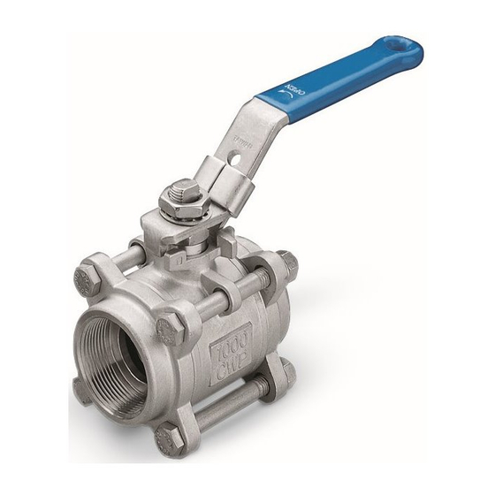
Wrenching here (Hex Flats)
when installing or removing
pipe this end.
Issue Date: 1/02
Wrenching here (Hex Flats)
when installing or removing
pipe this end.
Figure 1
Advertisement
Table of Contents

Related Manuals for metso automation VALUE-LINE 6F Series


Summary of Contents for metso automation VALUE-LINE 6F Series
- Page 1 VALVE DOES NOT TURN OUT OF THE VALVE BODY. (BODY/BODY CAP JOINT IS A RIGHT HAND THREAD.) NOTE: IF FITTING OF PIPE REMOVAL IS TO BE A REGULAR PRACTICE, METSO AUTOMATION RECOMMENDS EITHER THE WELDED BODY CAP VERSION OF THE ELIMINATOR®...
- Page 2 If the ball (3) and seats (5) do not fall from the body 9. Insert the body cap (2), screw it down and tighten to with the ball in the fully closed position, use a piece of the required torque, (see Table 1 for Body Cap wood or some other soft material to gently tap the ball Torque specifications).
- Page 3 PARTS LIST ITEM PART NAME QTY. Body Body Cap Ball Stem Seat Body Seal Stem Seal Stem Bearing Lockwasher Sec. Stem Seal Handle Stem Nut Comp. Ring 3" (DN 80) VALVES ONLY Figure 2...
- Page 4 Metso Automation, Field Systems Division Europe, Levytie 6, P.O.Box 310, 00811 Helsinki, Finland. Tel. int. +358 20 483 150. Fax int. +358 20 483 151 Europe (UK), 8 Pipers Wood Industrial Park, Waterlooville, Hampshire PO7 7XU UK. Tel. int. +44 (0)23 9223 8500. Fax int. +44 (0)23 9223 8510 North America, 44 Bowditch Drive, P.O.Box 8044, Shrewsbury, Massachusetts, 01545-8044 USA.
Need help?
Do you have a question about the VALUE-LINE 6F Series and is the answer not in the manual?
Questions and answers