
Subscribe to Our Youtube Channel
Related Manuals for SIGNALCORE SC5405A


Summary of Contents for SIGNALCORE SC5405A
- Page 1 SC5405A 1 MHz to 3.9 GHz RF Upconverter for PXI Express Operating & Programming Manual © 2015-2020 SignalCore, Inc. support@signalcore.com...
-
Page 2: Table Of Contents
SC5405A - Theory of Operation Overview Signal Path Description Local Oscillator Description Frequency Tuning Modes Setting the SC5405A to Achieve Best Dynamic Range Operating the SC5405A Outside Normal Range SC5405A Programming Interface Device Drivers Using the Application Programming Interface (API) - Page 3 Setting Spectral Inversion in the RF Storing Data into the User EEPROM Space Setting the Phase of the RF Signal Querying the SC5405A - Writing To Request Registers Reading the Device Status Reading the Device Temperature Reading the Calibration EEPROM...
-
Page 4: Important Information
Please contact SignalCore if errors are suspected. In no event shall SignalCore be liable for any damages arising out of or related to this document or the information contained in it. -
Page 5: Copyright & Trademarks
SignalCore, Incorporated respects the intellectual property rights of others, and we ask those who use our products to do the same. Our products are protected by copyright and other intellectual property laws. Use of SignalCore products is restricted to applications that do not infringe on the intellectual property rights of others. -
Page 6: Recycling Information
Laboratory Equipment include EN 61326-1:2013 and EN 55011:2009 for EMC, and EN 61010-1 for product safety. Recycling Information All products sold by SignalCore eventually reach the end of their useful life. SignalCore complies with EU Directive 2012/19/EU regarding Waste Electrical and Electronic Equipment (WEEE). Warnings Regarding Use of SignalCore Products... -
Page 7: Getting Started
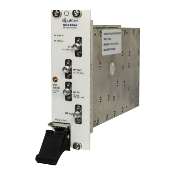
Software Installation USB Flash Drive (may be combined with other products onto a single drive) Setting Up and Configuring the SC5405A The SC5405A is designed for use in a PXI Express (PXIe) or PXIe hybrid chassis. Chassis manufacturers must provide at least the minimum required per-slot power dissipation cooling capability to be compliant with the PXIe specifications. - Page 8 The SC5405A is a PXIe RF upconverter with all user I/O located on the front face of the module as shown in Figure 1. Each I/O location is discussed in further detail below. Figure 1. PXI Express front view of the SC5405A.
-
Page 9: Signal Connections
50 Ω and drives 0 dBm into a 50 Ω load. Indicator LEDs The SC5405A provides visual indication of important modes. There are two LED indicators on the device. Their behavior under different operating conditions is shown in Table 1. -
Page 10: Sc5405A - Theory Of Operation
P E R A T I O N Overview The SC5405A operates on the principle of heterodyning, a process whereby an incoming RF/IF signal is mixed with specific oscillator frequencies in stages, producing both sum and difference frequency products. At each stage, the summed frequency product (or image) is removed through low-pass filtering, allowing the difference frequency product to continue through the signal path. -
Page 11: Signal Path Description
IF frequencies from appearing at the RF output port. The SC5405A exhibits very low phase noise of -107 dBc/Hz at 10 kHz offset on a 1 GHz RF carrier with a typical noise floor of -150 dBm/Hz. The noise floor can be further reduced below -165 dBm/Hz by enabling the internal preamplifier. - Page 12 Ref. In 10 MHz PLL, Attenuator, ADC, DAC, other devices Ref. Out Power PXIe 10/100 MHz SPI, RS-232, USB Module A Regulation 3.9 GHz Three Stage Upconverter Figure 3. Block diagram of the SC5405A. SC5405A Operating & Programming Manual Rev 2.1...
-
Page 13: Local Oscillator Description
DDS-generated spurs are suppressed within the architecture, LO1 is made to fine tune to exact frequencies, that is, the frequency synthesized is an exact integer multiple or division of the reference signal. SC5405A Operating & Programming Manual Rev 2.1... - Page 14 10 MHz TCXO for frequency accuracy and stability. For better frequency accuracy and stability than the TCXO onboard the SC5405A, or for frequency synchronization, the user can programmatically set the device to phase lock the TCXO to an external 10 MHz reference source by programming the REFERENCE_SETTING register.
-
Page 15: Frequency Tuning Modes
The SC5405A is designed for a nominal input IF level of 0 dBm. Depending on the application, the user will need to set the appropriate gain of the device (via attenuation), and the output level, to suit the particular application. -
Page 16: Operating The Sc5405A Outside Normal Range
Operating the SC5405A Outside Normal Range The SC5405A is capable of tuning below 1 MHz and above 3.9 GHz. These frequencies lie outside of the specification range and performance will be degraded if operated in these outer margins. For some applications, the reduced dynamic range or elevated spurious levels in these ranges may not pose an application concern. -
Page 17: Sc5405A Programming Interface
SignalCore for additional example code and hardware details. Using the Application Programming Interface (API) The SC5405A API library functions make it easy for the user to communicate with the device. Using the API removes the need to understand register-level details - their configuration, address, data format, etc. -
Page 18: Setting The Sc5405A - Writing To Configuration Registers
The data bytes contain the frequency tuning word in Hertz. For example, to tune to a frequency of 2.4 GHz, the data word would be d2400000000 in decimal or 0x8F0D1800 in hexadecimal. SC5405A Operating & Programming Manual Rev 2.1... -
Page 19: Changing The Attenuator Settings
“ref in” port. Asserting bit 1 low disables export of the internal clock. Asserting bit 1 high enables the device to export a 10 MHz signal through the “ref out” port. Asserting high bit 1 and bit 2 exports a 100 MHz signal. SC5405A Operating & Programming Manual Rev 2.1... -
Page 20: Adjusting The Reference Clock Accuracy
Adjusting the Reference Clock Accuracy The frequency precision of the SC5405A’s 10 MHz TCXO is set by the device internally. The device writes the factory calibrated value to the reference DAC on power-up. This value is an unsigned 16-bit number stored in the EEPROM (see the calibration EEPROM map). -
Page 21: Querying The Sc5405A - Writing To Request Registers
Table 4. It is important to note that the first local oscillator has three phase detectors in the synthesizer, so all three phase detectors must be ANDed to indicate the proper phase-locked status. The three bits that indicate the status of the three phase detectors are [13], [10], and [9]. SC5405A Operating & Programming Manual Rev 2.1... -
Page 22: Reading The Device Temperature
RF signal as the serial clock potentially modulates the local oscillators. Furthermore, once the SC5405A stabilizes in temperature, repeated readings will likely differ by as little as 0.25 °C over extended periods of time. Given that the gain-to-temperature coefficient is on the order of 0.06 dB/°C, gain changes between readings will be negligible. -
Page 23: Reading The Calibration Eeprom
*(float *)&uint32_value; Reading the User EEPROM Once data has been written to the user EEPROM, it can be retrieved using the process outlined above for reading calibration data by calling the FETCH_USER_EEPROM registers. SC5405A Operating & Programming Manual Rev 2.1... -
Page 24: Working With Calibration Data
[33x50] RF calibration Table 5 lists the calibration EEPROM map of the SC5405A, indicating how and where board information and calibration data are stored. Since there are only 16k bytes on the EEPROM, SignalCore recommends that all data be read into host memory on initialization of the device and parsed for further mathematical manipulation. -
Page 25: Eeprom Data Content
Product Serial Number (0x04). This is an unsigned integer value that contains the SC5405A serial number. It is unique for every product produced. It is used for the purpose of tracking the history of the product. - Page 26 Table 8. An example of IF attenuation calibration. IF3_Attenuator 1 0.973 1.927 2.948 3.912 28.630 29.634 IF3_Attenuator2 0.989 1.970 2.998 3.989 28.890 29.874 IF2_ Attenuator 0.995 2.028 3.038 4.023 28.868 29.854 SC5405A Operating & Programming Manual Rev 2.1...
-
Page 27: Frequency Correction
RF attenuator for fifty frequency points that span the operational frequency range of the SC5405A. Data is read in concatenation of rows. For example, all the frequency values are read in first, then the preamplifier gain values, followed by the zero attenuation- setting gain, etc. - Page 28 The function sc5405a_CalcGain uses six localized [X] points to compute the interpolated point. Using localized points, the example on Table 10 is re-tabulated in Table 11. Similarly, frequency dependent preamplifier gain and RF attenuation may be derived. SC5405A Operating & Programming Manual Rev 2.1...
-
Page 29: If Response Correction
However, for a large bandwidth signal that spans several MHz, it is important to apply gain and phase correction to the offset frequencies; those that are SC5405A Operating & Programming Manual Rev 2.1... - Page 30 IF. Although SignalCore performs calibration of the amplitude and phase over the bandwidth of the IF filters (available on the device calibration EEPROM), it is recommended that the user perform in-situ system equalization for digital broadband applications for improved performance.
-
Page 31: Software Api Library Functions
The functions listed below comprise the function set of the dynamic-linked library (Windows operating systems) and shared library (Linux operating system) versions of the SC5405A API. The LabVIEW palette library differs slightly due to the unique requirements of the LabVIEW programming environment (e.g., LabVIEW already provides standard math functions for curve fitting with spline interpolation). -
Page 32: Constants Definitions
SignalCore defines the following constants and types which are contained in the C header file, sc5405a.h. These constants and types are useful not only as an include file for developing applications using the SC5405A libraries, but also for writing device drivers independent of those provided by SignalCore. -
Page 33: Type Definitions
// gain error when spectral inversion enabled unsigned int tcxoDac; // The TCXO dac value at T0 calibrationData_t; typedef struct attenuator_t unsigned int if3Atten2Value; unsigned int if3Atten1Value; unsigned int rfAttenValue; unsigned int if1AttenValue; attenuator_t; typedef struct deviceStatus_t bool tcxoPllLock; SC5405A Operating & Programming Manual Rev 2.1... -
Page 34: Function Definitions And Usage
Function Definitions and Usage The functions listed below are found in the sc5405a.dll dynamic linked library These functions are also provided in the SC5405A LabVIEW palette, except in cases where an existing native function already exists to perform the same or similar task. The LabVIEW functions contain context help (Ctrl+H) to provide further clarification of each function. - Page 35 = 0; i< MAXDEVICES; i++) visaResource[i] = (char*)malloc(sizeof(char)*1000); status = sc5405a_ListResources(visaResource, &devicesFound); (devicesFound == 0) (i = 0; i< MAXDEVICES;i++) free(visaResource[i]); free(visaResource); printf("There are %d SignalCore SC5405A devices found. \n", devicesFound); (i = 0;i<devicesFound;i++) printf("%d. %s \n", i + 1, visaResource[i]);...
- Page 36 See the register map in Table 3 for more information. Example: To read the status of the device: unsigned int deviceStatus; status = sc5405a_RegRead(deviceHandle,0x18,0x01,&deviceStatus); Function: sc5405a_InitDevice Definition: int sc5405a_InitDevice(unsigned int *deviceHandle, bool Mode) Return: The status of the function SC5405A Operating & Programming Manual Rev 2.1...
- Page 37 (values to the attenuators contained in type) Description: sc5405a_SetSignalChain sets all the attenuators and the preamp state. This simplifies the programming flow when used with sc_5405a_CalcAutoAttenuation, which returns the attenuator_t structure. SC5405A Operating & Programming Manual Rev 2.1...
- Page 38 (enables phase locking to an external source) bool RefOutEnable (enables the clock to driven out the REF OUT port) bool Clk100Enable (changes REF OUT between 10MHz to 100 MHz) Description: sc5405a_SetReferenceClock configures the reference clock behavior of the device. SC5405A Operating & Programming Manual Rev 2.1...
- Page 39 1.25 MHz. Under normal mode 0, this spur is typically < -120 dBm and by turning on mode 1 improves this in most devices. SC5405A Operating & Programming Manual Rev 2.1...
- Page 40 Example: Code showing how to use this function: deviceStatus_t *devStatus; devStatus = (deviceStatus_t*)malloc(sizeof(deviceStatus_t)); status = sc5405a_GetDeviceStatus(deviceHandle, devStatus); if(devStatus->vcxoPllLock) printf("The 100 MHz is phase-locked \n"); else printf("The 100 MHz is not phase-locked \n"); free(deviceStatus); SC5405A Operating & Programming Manual Rev 2.1...
- Page 41 (EEPROM start memory address) Output: unsigned char *byteData (the read 64 bytes of data) Description: sc5405a_ReadUserEepromBulk reads back 64 bytes beginning at the start memory address of the user EEPROM. SC5405A Operating & Programming Manual Rev 2.1...
- Page 42 (structured calibration data) Description: sc5405a_GetCalData returns the device attributes such as serial number, calibration date, and also structured calibration data used for gain calculation and correction. Example: See code block example for sc5405a_ConvertRawCalData. SC5405A Operating & Programming Manual Rev 2.1...
- Page 43 Example: Allocating memory for the input and output parameters in C and calling the function. Similarly, allocated memory must be de-allocated when no longer used or when the program quits. SC5405A Operating & Programming Manual Rev 2.1...
- Page 44 //read in raw calibration status = sc5405a_GetRawCal(deviceHandle, rawCal); //Calling the function to structure the calibration data status = sc5405a_convertRawCalData(rawCal, devAttr, calData); //alternatively instead of calling the above 2 functions status = sc5405a_GetCalData(deviceHandle, devAttr, calData); SC5405A Operating & Programming Manual Rev 2.1...
- Page 45 Description: sc5405a_CalcAutoAttenuation returns the set of attenuation settings for all the attenuators that will configure the SC5405A for best dynamic range operation based on user input parameters such as frequency, mixer level, etc. The values are calculated to maintain a good balance between the signal-to-noise dynamic range and the linearity dynamic range.
- Page 46 (temperature value of the device in degrees Celsius) calibrationData_t *calData (calibration data for the device) Output: float *conversionGain (calculated calibrate conversion gain for current settings) Description: sc5405a_CalcGain calculates the calibrated gain based on the current user settings. SC5405A Operating & Programming Manual Rev 2.1...
- Page 47 (16-bit rawTempData stored in a 32-bit unsigned int) Output: float *temperature (temperature value of the device in degrees Celsius) Description: sc5405a_ConvertRawTempData converts the rawTempData variable into a floating point number. SC5405A Operating & Programming Manual Rev 2.1...
- Page 48 (the numbers of points in xArray) double x (the value at which interpolation is performed) Output: double *interpolatedYValue (the corresponding interpolated value at x) Description: sc5405a_SplineInterp returns the spline interpolated value. SC5405A Operating & Programming Manual Rev 2.1...
-
Page 49: Calibration & Maintenance
The SC5405A is factory calibrated and ships with a certificate of calibration. SignalCore strongly recommends that the SC5405A be returned for factory calibration every 12 months or whenever a problem is suspected. The specific calibration interval is left to the end user and is dependent upon the accuracy required for a particular application. - Page 50 IEC testing standards and EU Directive references. Rev 2.0.0 Removed Appendix A (specifications are now available in separate datasheet document). Updated a few grammatical errors; added new front interface drawing; updated title Rev 2.1.0 page picture. SC5405A Operating & Programming Manual Rev 2.1...
Need help?
Do you have a question about the SC5405A and is the answer not in the manual?
Questions and answers