
Related Manuals for Elmo Platinum Maestro


Summary of Contents for Elmo Platinum Maestro
- Page 1 Platinum Maestro Network Motion Controller Installation Guide October 2018 (Ver. 1.008) www.elmomc.com...
- Page 2 This guide is delivered subject to the following conditions and restrictions: • This guide contains proprietary information belonging to Elmo Motion Control Ltd. Such information is supplied solely for the purpose of assisting users of the Platinum Maestro motion controller in its installation. •...
- Page 3 Power Supply ......................8 Physical Specifications ....................8 General ........................8 Environmental Conditions ..................8 Chapter 4: Platinum Maestro Software Specifications ........... 9 Operating System ....................... 9 Axes ..........................9 Motion Modes and Interfaces .................. 10 Drive Communication Bridge Support..............11 General ........................
- Page 4 Memory Card (Push-push Type) SCHA ............ 31 7.10 Powering Up ......................32 7.11 Initializing the System ....................32 Chapter 8: Platinum Maestro Dimensions ..............33 Chapter 9: Compliance with Standards ............... 35 Low Voltage Directive ....................35 Other Compliant Standards ..................35 |Cautions|www.elmomc.com...
- Page 5 Chapter 1: Safety I nform ation In order to achieve the optimum, safe operation of the Platinum Maestro Multi-Axis Controller, it is imperative that you implement the safety procedures included in this installation guide. This information is provided to protect you and to keep your work area safe when operating the Platinum Maestro and accompanying equipment.
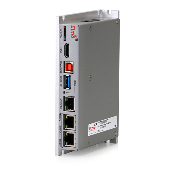
- Page 6 2.1 Description The Platinum Maestro is Elmo’s premium network motion controller. It works in a network based system in conjunction with Elmo’s intelligent servo drives to provide a total multi-axis motion control system solution.
- Page 7 Network Motion Controller Installation Guide MAN-P-MAESTRO-IG (Ver. 1.008) Chapter 3: Technical Specifications 3.1 Processor System Feature Details Processor Computational core system based on Dual Core (2×1.5 GHz) On Board Flash 4 GByte DDR-3, 4 GByte, 64 bit bus width, (Operational at Full Core Rate) SD Card MicroSD™...
- Page 8 3.5 General Feature Details Real Time Clock Option with 3V battery Internal System BIT The Platinum Maestro supports internal hardware BIT (Built-in-tests) procedures to check the system integrity level on each power up Diagnostic LEDs EtherCAT and Ethernet activity 3.6 Environmental Conditions...
- Page 9 4.1 Operating System Feature Details Linux Operating System With Elmo’s RT extension for real-time motion control support Motion Programming and Native C Programming, running on the target CPU. Compiling and Debugging debugging via the Eclipse IDE using GCC under Cygwin.
- Page 10 Cycle Jitter: < 100 µs for CAN Sync message initiation (actual jitter dependent on the CAN network’s physical limitations) 4.3 Motion Modes and Interfaces Feature Details The Platinum Maestro 64 bit, real-time, double precision profile calculations, allowing motion interfaces use full on-the-fly control over speed, acceleration, deceleration and PLCopen Standard...
- Page 11 MAN-P-MAESTRO-IG (Ver. 1.008) Feature Details Internal Software libraries, for "C" user programs are provided, to write user code running on the Platinum Maestro target processor (native mode). Data Recording 8 MB data recording Up to 64 vectors can be recorded simultaneously.
- Page 12 MAN-P-MAESTRO-IG (Ver. 1.008) 4.6 Communication Options The Platinum Maestro can communicate with a host PC either via a standard Ethernet port or through USB using a binary protocol for maintenance. The Platinum Maestro communicates with its network devices using either EtherCAT or CAN networks.
- Page 13 Platinum Maestro Software Manual. If you have not already done so, follow the instructions in the Installation Guide that arrived with your servo drive, and install a drive. At least one drive needs to be connected to the Platinum Maestro in order for it to function as a motion controller. |Communication Options|www.elmomc.com...
- Page 14 I nstallation 6.1 Environmental Conditions You can guarantee the safe operation of the Platinum Maestro by ensuring that it is installed in an appropriate environment. For safe operation of the Platinum Maestro make sure it is installed in an appropriate environment.
- Page 15 Network Motion Controller Installation Guide MAN-P-MAESTRO-IG (Ver. 1.008) If you are using CAN networking, verify that you have CAN termination resistors (dongles), illustrated below. |Unpacking the Components|www.elmomc.com Table of Contents...
- Page 16 6.3.1 Wall Mount Two M4 round head screws, one through each opening in the heat sink, are used to mount the Platinum Maestro (see the diagram below) on a wall. Figure 2: Wall Mounting the Platinum Maestro 6.3.2 Surface Mount Use four M4 round head screws, one through each opening in the heat sink to connect the Platinum Maestro to a surface.
- Page 17 7.1 Connectors 7.1.1 Wiring the Platinum Maestro Once the Platinum Maestro is mounted, you are ready to wire the device. Proper wiring, grounding and shielding are essential for ensuring safe, immune and optimal performance of the Platinum Maestro. Use shielded CAT5e/6 cables for Ethernet and EtherCAT communication.
- Page 18 3-Pin Phoenix Plug (MC 1.5/3-G-3.81) (MC 1.5/3-ST-3.81) Type Manufacturer & Part No. Mating Connector 3.81 mm pitch Phoenix Header Phoenix Plug (supplied) Header and Plug MC 1.5/3-G-3.81 MC 1.5/3-ST-3.81 Table 2: Platinum Maestro Power and Ground Connectors |Connectors|www.elmomc.com Table of Contents...
- Page 19 The supplied power must be within the rated voltage range of 12 V to 32 V. Connect the DC output from the power supply to the power input port on the Platinum Maestro using the 3-pin power plug provided.
- Page 20 Figure 5 shows the position of the red/green dual LED, which is used for immediate indication of the Initiation and Working states. Figure 5: Platinum Maestro Status Indicator The red/green dual LED is used for immediate indication of the following states: Initiation state: In this state the LED indicates whether the Maestro is in the boot state •...
- Page 21 Network Motion Controller Installation Guide MAN-P-MAESTRO-IG (Ver. 1.008) 7.5 EtherCAT Master Connectors 7.5.1 EtherCAT Master Port 1 Connector Signal Function Ethernet_TX+ Ethernet transmit + Ethernet_TX- Ethernet transmit - Ethernet_RX+ Ethernet receive + Ethernet_RX- Ethernet receive - 7, 8 Connector Location Cable Connector 8 pin RJ-45 plug...
- Page 22 Network Motion Controller Installation Guide MAN-P-MAESTRO-IG (Ver. 1.008) 7.5.2 EtherCAT Master Activity Indicators Figure 7: EtherCAT Slave Status LEDs The green LED is the link/activity indicator (Figure 7). It shows the state of the applicable physical link and the activity on that link. The amber LED is the speed indicator (Figure 7).
- Page 23 7.5.3 EtherCAT Network The Platinum Maestro is the master of the EtherCAT network and must always be the first device in the line. The Ethernet Master 1 port of the Platinum Maestro should be connected to the EtherCAT In port of the next device down the line.
- Page 24 Network Motion Controller Installation Guide MAN-P-MAESTRO-IG (Ver. 1.008) 7.5.4 Ethernet Host Connectors 100Base-T 1000Base-T Signal Description Signal Description Transmit Data+ BI_DA+ BiDirectional Data A+ Transmit Data- BI_DA- BiDirectional Data A- Receive Data+ BI_DB+ BiDirectional Data B+ Not connected BI_DC+ BiDirectional Data C+ Not connected BI_DC- BiDirectional Data C-...
- Page 25 Network Motion Controller Installation Guide MAN-P-MAESTRO-IG (Ver. 1.008) 7.5.4.1 Ethernet Host Activity Indicators Figure 9: Ethernet Host Status LEDs The green LED is the link/activity indicator (Figure 9). It shows the state of the applicable physical link and the activity on that link. The white LED is the speed indicator (Figure 9).
- Page 26 When connecting the Ethernet communication cable use a shielded CAT5e/6 Ethernet cable. The Platinum Maestro connects to a PC either directly or through a hub, switch or router. Use a standard shielded CAT5e/6 Ethernet cable. Figure 10: Platinum Maestro Connected to a Network...
- Page 27 • Connect a 120 Ω termination resistor to each end of the network cable. (The Platinum Maestro does not have an internal terminal.) • A termination resistor is not required to be installed at the unused CAN port on the Platinum Maestro.
- Page 28 Network Motion Controller Installation Guide MAN-P-MAESTRO-IG (Ver. 1.008) • Use the CAN termination dongle supplied as a second “device end”. Simply insert the termination resistor into the CAN connector of the second end device on the bus. This is only possible if there are two CAN connectors. Figure 12: Connecting a 120 Ω...
- Page 29 Network Motion Controller Installation Guide MAN-P-MAESTRO-IG (Ver. 1.008) 7.7 USB 2.0 Type A The Platinum Maestro supports USB 2.0. Signal Function USB VBUS USB VBUS 5 V USBD- USB _N line USBD+ USB _P line USB COMRET USB communication return...
- Page 30 Network Motion Controller Installation Guide MAN-P-MAESTRO-IG (Ver. 1.008) 7.8 Device USB 2.0 Type B The Platinum Maestro supports USB 2.0 (Host mode) in communication speed of Low-Speed (1.5Mbs), Full-Speed (12Mbs), and High-Speed (480Mbps). Signal Function USB VBUS USB VBUS from host...
- Page 31 Network Motion Controller Installation Guide MAN-P-MAESTRO-IG (Ver. 1.008) 7.9 microSD™ Memory Card (Push-push Type) SCHA Connector Location Cable Connector MicroSD Memory Card |microSD™ Memory Card (Push-push Type) SCHA|www.elmomc.com Table of Contents...
- Page 32 After the Platinum Maestro has been mounted, check that the cables are intact. The Platinum Maestro is then ready to be powered up. 7.11 Initializing the System After the Platinum Maestro has been connected and mounted, the system must be set up and initialized. The minimum system requirements for a setup are: •...
- Page 33 Network Motion Controller Installation Guide MAN-P-MAESTRO-IG (Ver. 1.008) Chapter 8: Platinum M aestro Dim ensions |Initializing the System|www.elmomc.com Table of Contents...
- Page 34 Network Motion Controller Installation Guide MAN-P-MAESTRO-IG (Ver. 1.008) |Initializing the System|www.elmomc.com Table of Contents...
- Page 35 The related standards below apply to the performance of the motion controller as stated in the environmental conditions paragraph 6.1 Environmental Conditions. The Platinum Maestro does not require UL compliance, as its maximum voltage is 32 VDC. In compliance with EN 60204-1...
- Page 36 Environmental In compliance with 2002/96/EC Waste Electrical and Electronic Equipment regulations (WEEE) Note: Out-of-service Elmo drives should be sent to the nearest Elmo sales office. In compliance with 2002/95/EC Restrictions on Application of Hazardous (effective July 2006) Substances in Electric and Electronic Equipment...
- Page 37 Network Motion Controller Installation Guide MAN-P-MAESTRO-IG (Ver. 1.008) |Other Compliant Standards|www.elmomc.com Table of Contents...
Need help?
Do you have a question about the Platinum Maestro and is the answer not in the manual?
Questions and answers