Table of Contents
Advertisement
Quick Links
Advertisement
Table of Contents

Related Manuals for Elmo Gold Maestro G-MAS


Summary of Contents for Elmo Gold Maestro G-MAS
- Page 1 G‐MAS – Gold Maestro Software User’s Manual March 2011 (Ver. 1.0) www.elmomc.com ...
- Page 2 G‐MAS – Gold Maestro Software User’s Manual Software User Manual 1‐2 XXXXXXXXXXXX(0.01) Important Notice This document is delivered subject to the following conditions and restrictions: • This document is copyrighted and all rights are reserved by Elmo Motion Control Ltd. This product may not, in whole or in part, be copied, photocopied, reproduced, translated, or reduced to any electronic medium or machine‐readable form without prior consent, in writing, by Elmo Motion Control Ltd. • This document contains proprietary information belonging to Elmo Motion Control Ltd. Such information is supplied solely for assisting users of Gold Maestro Network Motion Controller. • The text and graphics included in this document are for the purpose of illustration and reference only. The specifications on which they are based are subject to change without notice. • Elmo Motion Control and the Elmo Motion Control logo are trademarks of Elmo Motion Control Ltd. Document no. XXXXXXXXXXXXXXXXX Copyright © 2011 Elmo Motion Control Ltd. All rights reserved. ...
-
Page 3: Table Of Contents
G‐MAS – Gold Maestro Software User’s Manual Software User Manual 1‐1 XXXXXXXXXXXX(0.01) Table of contents Chapter 1: About the G‐MAS and this manual..............1‐3 What is the G‐MAS ..................1‐3 1.1. G‐MAS Features ....................1‐4 1.2. What the Document Covers and How to Use It ..........1‐5 1.3. Chapter 2: Just Before Starting Up ................2‐6 Preparing Your Computer ................2‐6 2.1. Using the Manual’s Examples .................2‐6 2.2. Chapter 3: Programming Practices and Guidelines ............3‐9 3.1. Projects and files...................3‐9 3.1.1. Project Location and Naming............3‐10 Project’s Files ................3‐11 3.1.2. Project’s Description Files ............ - Page 4 G‐MAS – Gold Maestro Software User’s Manual Software User Manual 1‐2 XXXXXXXXXXXX(0.01) The device network ..................4‐53 4.3. 4.4. Additional tools...................4‐54 KPA Studio .................. 4‐54 4.4.1. IP Configuration over USB ............4‐54 4.4.2. Chapter 5: The XYZ robot example ................5‐55 Chapter 6: Further Programming Examples..............6‐56 Chapter 7: PC Software Installation and how to use ...........7‐57...
-
Page 5: Chapter 1: About The G-Mas And This Manual
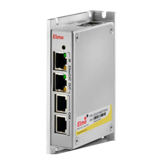
G‐MAS – Gold Maestro Software User’s Manual Software User Manual 1‐3 XXXXXXXXXXXX(0.01) Chapter 1: About the G-MAS and this manual This chapter describes the G‐MAS product and the organization of this manual. Persons beginning to understand the G‐MAS and program it, should read this manual carefully. However, experienced G‐MAS users may omit this chapter. 1.1. What is the G-MAS The Gold Maestro – G‐MAS is an advanced multi‐axis machine controller. It is a programmable control unit, with built‐in, ready‐to‐use, standardized functionalities for communications, motions, emergencies, timing, events and all that is required (and desired) to implement a complete multi‐axis motion control system. The figure below presents the structure of a motion control system based on the G‐MAS and Elmo’s digital drives. This system is based on the following three layers: • Host computer (or PLC or HMI Panel) • G‐MAS • Devices (Digital Drives, I/O controllers, network encoders …) The machine’s host computer (or PLC, HMI panel) typically executes the interfaces to the machine operator and performs high‐level management and machine algorithms, as necessary. ... -
Page 6: G-Mas Features
G‐MAS – Gold Maestro Software User’s Manual Software User Manual 1‐4 XXXXXXXXXXXX(0.01) Digital servo drives control and drive motors, with each drive generally responsible for a single axis (control, motions, safety, limits, etc.), as well as some I/Os that may be connected to the digital servo drive. With Elmo intelligent digital servo drives, each drive can be programmed to perform simple and advanced processes, which is only limited to axis level process (in contrast to machine, or multi‐ axes level). I/O controllers and other devices can be added to the device network. The host computer (or PLC, HMI panel) is responsible for user interfaces and high‐level machine processes, whereas the digital servo drives (and I/Os controllers) execute axis or I/O level processes. Therefore, an intermediary layer is necessary to perform the machine’s sequences and multi‐axis synchronized motions. This is exactly where the G‐MAS comes in. The G‐MAS is located in the intermediary layer. It receives high‐level commands from the host computer, performs the required machine sequences, calculates multi‐axis motions and, opportunely, communicates via the device network to synchronously send commands to each axis. Obviously, the G‐MAS also collects statuses from the network devices and in turn sends its own statuses to the host computer. From the network devices view, the G‐MAS is important, since each network device views only a very narrow (axis, I/O) portion of the overall system and therefore cannot create or control overall system sequences or multi‐axis synchronized motions. The network devices require a device like the G‐MAS to take this responsibility. From the host computer (or PLC, HMI Panel) view, the G‐MAS is not as important, as in theory, one can implement all the functions of the G‐MAS into the host computer. However, this entails a variety of significant drawbacks e.g. huge development time, significant risks, non‐modular implementation, “inventing the wheel” etc. that are easily and elegantly solved using the G‐MAS. With its turnkey, in‐built functionality (standard implementation of: PLCopen motions, Ethernet communications, CANopen, CANopen over EtherCAT, etc.) and support for C user programs, to easily implement a multi‐axis motion control system, you only need to write your first C program for the G‐ MAS. This is probably why you are now reading this manual… 1.2. G-MAS Features The following presents some of the G‐MAS features. You may refer to Elmo’s website at www.elmomc.com for additional detailed information and brochures. •... -
Page 7: What The Document Covers And How To Use It
• Built‐in functional block libraries: Communication with host CANopen over CAN and EtherCAT PLCopen motion Events Data recording • Programming: Native application 'C' programming on the target IEC 61131‐3, PLCopen (future feature) • Package and power supply: Very compact, space saving package. The Gold Lion for embedded military applications. DC powered: 14 V to 196 V. It is important to note that one of the main criteria that guided the G‐MAS development (together with all Elmo’s Gold family products) was to use market‐leading standards wherever possible. Furthermore, each standard was accurately implemented, ensuring mandatory complete implementation of the standard. With Elmo’s Gold product family, this can be found, for example, in the host communication (MODbus, Ethernet/IP), Device Network (CANopen, CANopen over EtherCAT), safety, PLCmotion library, I/Os interface circuits, etc. 1.3. What the Document Covers and How to Use It This manual is organized to create a progressive path for the user starting from the G‐MAS basics to gradually achieve the potential for advanced and complex systems programming. The manual begins explaining the G‐MAS structure and programming guidelines and continues with a detailed explanation of an Application program written for an XYZ robot. The explanation starts with the top‐level code structure and later, systematically, immerses into the code details. Therefore, for beginners, it is recommended to read this manual chapter‐by‐chapter. The manual and its code examples are organized to allow the reader to learn, chapter by chapter, firstly about the G‐MAS functions and ease of use, and then progressively, about the details of implementation, with increasing details revealed in later chapters or explanation. ... -
Page 8: Chapter 2: Just Before Starting Up
G‐MAS – Gold Maestro Software User’s Manual Software User Manual 2‐6 XXXXXXXXXXXX(0.01) Chapter 2: Just Before Starting Up This chapter presents the required preparations before you can start using the G‐MAS and its PC software environment. In addition, it explains how the incorporated examples relate to Elmo’s demo suitcase, and how they can be adapted to match your specific system. This chapter must be read, and the preparations described within, implemented, to be properly proficient in operating the G‐MAS and developing user programs for it. 2.1. Preparing Your Computer The PC software environment for the G‐MAS includes the EAS (Elmo Application Studio) and the C programming development environment. These application modules must be installed to be able to operate with the G‐MAS. The EAS is Elmo’s setup and maintenance application for the Gold line products, including the G‐MAS and Gold Drives. As a G‐MAS user, you will need this application to configure your system (network, devices, etc.), communicate with the G‐MAS, and to perform a variety of features incorporated within EAS, e.g. to create, record and display multi‐axis motions. The C programming development environment is necessary to develop (write, download, debug) C programs for the G‐MAS. Please refer to Chapter 7: PC Software Installation and how to use for details regarding the installation of the required G‐MAS software process, and how to use these software modules. Please continue using this manual only after properly installing the applications and understanding how to use them. The remainder of this manual assumes that the user is familiar with the application ... - Page 9 G‐MAS – Gold Maestro Software User’s Manual Software User Manual 2‐7 XXXXXXXXXXXX(0.01) The Gold Line demo suitcase includes two Gold line digital servo drives connected to the G‐MAS over EtherCAT while the SimplIQ Line demo suitcase includes two SimplIQ drives connected to the G‐MAS over the CAN bus. Therefore, the examples provided within this manual are adjusted to either configuration, whether Gold or SimplIQ demo system, and is mentioned within each example. However, not all examples may work for a different system configuration. It is therefore recommended to consider purchasing of a demo suitcase (Gold or SimplIQ, depending on your needs) for conveniently practicing this manual’s examples. Please address your local Elmo’s sales channel to order a demo suitcase. If you prefer to use your own system for practicing this manual’s examples, you will need to slightly modify them according to the structure of your own system. Use the guidelines described within the following the table to properly modify this manual’ examples. Necessary modifications for Necessary modifications for examples Your System Structure examples written for CAN written for EtherCAT Resource file that represents the system. Should call the GetCommStatistics() API in order to check that the network G‐MAS with 2xSimplIQ None setup is OK. This is instead of drives over CANbus NetworkInfo() which is for CAN. Change operation mode to Cyclic Position mode and not Interpolated Position. G‐MAS with 1xSimplIQ drive ...
- Page 10 G‐MAS – Gold Maestro Software User’s Manual Software User Manual 2‐8 XXXXXXXXXXXX(0.01) Necessary modifications for Necessary modifications for examples Your System Structure examples written for CAN written for EtherCAT G‐MAS with 1xGold drive As above As above over the CAN bus G‐MAS with NxGold drives As above As above over the CAN bus (N>2) ...
-
Page 11: Chapter 3: Programming Practices And Guidelines
G‐MAS – Gold Maestro Software User’s Manual Software User Manual 3‐9 XXXXXXXXXXXX(0.01) Chapter 3: Programming Practices and Guidelines This chapter describes the practices and guidelines used by Elmo’s team to developed examples and application programs for the G‐MAS. These guidelines are based on worldwide common C programming practices with some expansions required to create a complete set of guidelines and concepts for the G‐MAS C programming Most of the guidelines do not really affect the execution of the code (do not directly improve code size, or speed, or performance in general), so, why is it so important to use them? For the following reasons: 1. Most of the guidelines relate to code readability, portability, ease of development, and debugging. This means that your development process is assumed faster and easier with these guidelines. 2. Some of the guidelines, especially those that relate to programming concepts, are more than just “how to make my code clearer”. They really affect the ease of implementation, execution performance, and the time‐to‐market of your project. One of these guidelines is the concept of States Machine programming, as you will see later on this manual. It is one of few possible methods to implement machine sequences, and practically, it proved itself the simplest and the most successful method to use. 3. You can better use the examples and Case Studies provided by Elmo, as they are all written according to these guidelines and programming concepts. 4. And most important, to enable the best support you can get from Elmo. Application programs may become large and quite complex for significant projects. Using your own programming concepts, as good as they surely are, will make it much more difficult for Elmo’s support engineers to perform in‐depth analysis. You may need to send us your code, or parts of it, at some point in the future, and it may become impossible for us to analyze ... -
Page 12: Project Location And Naming
G‐MAS – Gold Maestro Software User’s Manual Software User Manual 3‐10 XXXXXXXXXXXX(0.01) 3.1.1. Project Location and Naming All projects (applications) shall be located under the C:\GMAS\MyGMASProjects directory, which is created during the software environment installation process. The root directory C:\ can be replaced with the actual name of your disk. Each project should be located within a specific directory under the above location, with only one project within a given directory. The name of a project’s directory should reflect the name of the project (application). For example, from Elmo’s set of C programs examples: “C_ReadDigitalInput” (see screen snapshot below). Note that the name of the project’s directory respects the following guidelines: • It reflects the project/application contents. • It has no spaces. • If it consists of few words, each word starts with a Capital letter for easy reading. • Finally, for convenience only, Elmo adds a prefix to the project’s name (in this case: “C_”) to force the list of the projects to appear in a given order within Windows explorer. This is done in order to organize our built‐in examples in a desired order for the readers of this manual. You are not required to add this prefix (see customer’s project WalkingRobotPrototype within the screen snapshot below). The above three guidelines for naming project’s directory, are also applicable for naming all of the project’s C and H files. The name must reflect the content of the file, include no spaces and each word in the name should start with a capital letter, e.g.: ReadDigitalInput.c ... -
Page 13: Project's Files
G‐MAS – Gold Maestro Software User’s Manual Software User Manual 3‐11 XXXXXXXXXXXX(0.01) Projects directory Walking Robot project Read Digital Input project 3.1.2. Project’s Files Each project will be based on a main C file, respecting the following guidelines: • Its name will be identical to the project’s directory name (without the prefix, if used). For example: ReadDigitalInput.c • It will include the main() function, which will be the first function within the file. Each project will also include a main header (*.h) file, which will be also named with the name of the project (e.g. ReadDigitalInput.h) and will include all definitions which are specific for the project (such as constants, functions prototypes, etc.). In addition, the developer can create additional code and header files, as may be needed to properly organize the various C functions. All files should be named using the above file naming guidelines. 3.1.3. Project’s Description Files Elmo highly recommends that an application programmer should add some files to a project’s directory that explain the project goals, tasks, methods of implementation, etc. It can be a simple readme file or files that are more complex (machine specification, motion sequences, machine’s ATP, design reviews for the implementation, etc.). This information, if supplied with the overall project code files (for a new member in the development team, and/or for Elmo’s staff for support, etc.) can significantly improve processes e.g. learning, support for the project, etc. Please refer to the project’s description files included with each of Elmo’s examples (located at C:\GMAS\MyGMASCProjects as part of the Development Software installation process) for examples of such files. ... -
Page 14: Functions, Variables And Constants
G‐MAS – Gold Maestro Software User’s Manual Software User Manual 3‐12 XXXXXXXXXXXX(0.01) 3.2. Functions, Variables and Constants The naming and usage of functions, variables and constants should abide by the following guidelines: • Functions should be named similarly to files. For example: MainTimer(). • Variables should also be named similarly, but should be preceded with the variable type in lower case, according to the table below. For example: iSpeed can be the name of an integer variable holding a value of speed. Type Prefix Example Integer i iMotorSpeed Unsigned integer ui uiUpperLimit Long l lPosition Unsigned long ul ulLimitPosition Short s sAnalogInput Unsigned short us usDigitalInputs Char ... -
Page 15: Wrapper Functions
G‐MAS – Gold Maestro Software User’s Manual Software User Manual 3‐13 XXXXXXXXXXXX(0.01) application should return a value to operating system upon exiting, please refer to the relevant example included within the examples directory (c:\GMAS\MyGMASCProjects). • A C file should “include” only the header files necessary. • The code should not include numbers. Constants should be defined within the relevant header file and the value of the constant should be defined only within the header file. For example: HOMING_SPEED. • This includes values like “0” and “1”. Define OK and NOT_OK (and/or similarly, like TRUE, FALSE). • Code should be vertically aligned and properly nested. • Use TABS, not spaces to align the code vertically. • Opening and closing brackets (“{“ and “}”) should be each written in a separate line. • Comments (files and functions titles, in‐line comments, end of line comments, etc.) should use the format (or style) as shown with the sample code at the end of this chapter. 3.4. Wrapper functions Wrapper functions files are files that hold a set of logically related functions (actually, a library of functions). Each function is written to “hide” a relatively complex process/code with a simple interface for the programmer. An example can be a Wrapper Functions file that will include a set of functions for motion. It may contain, for example, a function like MyMoveAbsolute(dSpeed, dPosition). This function has a very simple interface (can be easily used to create a motion, as all you need to enter are values for Speed and Position), but internally, it will use the less simple PLCopen Motion function, including parameters initializations, validity checks, etc. Wrapper Functions help to keep the main code cleaner and more elegant. While reading (and debugging/modifying) the main code, one would like to easily see the implemented machine sequence (program flow) and this can be done only if the details of the code are hidden within function calls. A call to a function named “MMC_InitSystem(…)” will be much clearer than placing the detailed code ... -
Page 16: Hiding Repeated Segments Of Code
G‐MAS – Gold Maestro Software User’s Manual Software User Manual 3‐14 XXXXXXXXXXXX(0.01) If these segments of code remain within the main code, the main code will become too complex, blocking reasonable reading and tracking of what is most important; the implementation of the machine sequences and logic. Wrapper Functions can be used to hide these segments of code. Such Wrapper Functions are supplied by Elmo so that our examples can be read and understood much easier. 3.4.2. Hiding Repeated Segments of Code Repeated segments of code, even if not complex, and even if important to understand the program flow (the machine sequences), can be hidden inside a Wrapper Function to minimize the main code length. 3.4.3. Providing Easier Interfaces Some of the built‐in G‐MAS Function Block functions have complex interfaces, i.e. a function with many arguments, with some of these arguments also complex structures. This complexity is necessary to maintain compatibility with standards like PLCopen Motion and to enable full operation of the function. However, in most situations, and your case may be one of them, the application does not need full operation of the Function Block, but only needs a small subset of the Function Block interfaces. Under these circumstances, the programmer (or Elmo within its examples) may define a new function that will have a simple interface with the program and will internally assume some defaults for the remaining functions arguments. An example can be a simple motion function (to be typically located within a Wrapper Functions file that will include many functions for simple motions), e.g. MoveAbs(iPosition). This function accepts only one argument, the desired position, and creates a motion to this target position, using the full mechanism of the PLCopen Motion Function Blocks. It will assume default values for the additionally needed arguments, like speed and acceleration, or will keep the values used recently – depending on the actual coding of the MoveAbs() function (this of course must be ... -
Page 17: Implementing Machine Sequences
G‐MAS – Gold Maestro Software User’s Manual Software User Manual 3‐15 XXXXXXXXXXXX(0.01) Elmo supplies a set of Wrapper Functions files as part of its set of examples. You can define and create your own set of Wrapper Functions files (starting from scratch or based on one of Elmo’s examples), as suitable for your projects and style of writing. Wrapper Functions files should follow the following guidelines: • Elmo’s supplied Wrapper Functions files should not be modified. Instead, if modifications are necessary, copy the file to a new file and modify it. • Each Wrapper Functions file should include a set of functions that are logically related. Each function should have a simple user interface. • Each Wrapper Functions file should be named to reflect its contents. For example: SimplifiedSynchronizedMotions.c. • Each Wrapper Functions C file should have a header file (*.h), with the same name. The header file will include definitions relevant to the Wrapper Functions file, as well as prototypes for the wrapper functions included within it. • The general (not example specific) Wrapper Functions files that are supplied by Elmo, are located under the G:\GMAS\GMASCWrapperFunctionsFiles. • Additional Wrapper Functions files that are more specific to a given project/application should be located within the project directory. • If a Wrapper Function acquires a number of assumptions (default values, keeping previous values, etc.), these assumptions must be clearly documented for the user. • It is strongly recommended that a Wrapper Function (unless it was written to a very specific and fixed project) will not include default values for parameters. An easy mistake can be, for example, to assume a value of 100000 (for example) for a simplified motion function. This may work perfectly for a given example, but will not be suitable for a future example, when no one will remember this default decision. Other solutions are recommended (for example, to include a Wrapper Function within the file that will be used to initialize all this default values from the ... - Page 18 • Capable to handle background system processes such as validation read, and handle statuses, emergencies, etc. Many tasks should be continuously or more accurately, periodically, handled by the application. These tasks should be executed independently of the machine status and/or mode of operation. • Capable to always be ready to receive incoming communication (typically, from the Host) with reasonable response time and more important, with pre‐defined limited response time. The application program should not be too busy (in terms of time) with any given task, and should always be able to obtain and properly respond to incoming communication. • Determinism. The application program should execute the same sequences, respond to incoming messages, and create communications to the device network, in a determined way, with little delays or jitters and within a predefined limit. • Maintainability. Finally, but not less important is the requirement for easy development and maintenance of the program. The program must be organized in a way that complex sequences can be easily written, controlled, and maintained. There are numerous methods to write a program that will answer the above requirements. For example: multi‐tasking and interrupts. Elmo has an extensive experience in the development of user applications. We have acquired this experience during many years of customers support and during in‐house development of user applications. Based on this experience, we have concluded that the optimal method to write programs for machine sequences is a structure that is based on States Machines. This programming structure optimally answers the above requirements. With a States Machine structure, a program does not need Multi‐Tasking (a complex structure for most programmers, and obviously most Motion Control engineers) and in most cases even interrupts are not required. All that is needed is an understanding of the basics of States Machine programming. The code then becomes very simple to develop and to maintain. All programs examples provided by Elmo are implemented using States Machine structure. It is strongly recommended to use this programming structure. It will enable easier use of Elmo’s examples, allow Elmo’s support team to provide better and faster support. In addition, it will shorten your time‐to‐market and reduce your development risks significantly. This is a good point to start explaining the details of States Machine programming structure. The explanation is not simple, and is presented in a systematic procedure. ...
-
Page 19: The Main() Program Structure
G‐MAS – Gold Maestro Software User’s Manual Software User Manual 3‐17 XXXXXXXXXXXX(0.01) 3.5.1. The main() program structure Elmo’s recommended structure for the main() function of a G‐MAS User Application program is presented in Figure 1: Figure 1: Main() program structure The main() starts with a call to MainInit(), a function that performs all program and system initializations (more on this later within the manual’s examples). After all initializations are completed, the MachineSequences() function is called. This function intentionally starts the execution of the machine sequences and motions. During the machine operation, the MachineSequences() function does not return to the main(), until the program requests to terminate (due to, e.g. errors, user request to close, etc.). When the machine operation is complete, the Machine Sequences() function returns to the main(), which calls the MainClose() function to close everything that requires closing, before the program terminates. This is the main() function of the program. Simple and clean as possible. Now we progress into the MachineSequences() function to find the implementation of the machine sequences, using the States Machine structure. ... -
Page 20: The Machinesequences() Function
G‐MAS – Gold Maestro Software User’s Manual Software User Manual 3‐18 XXXXXXXXXXXX(0.01) 3.5.2. The MachineSequences() Function Figure 2 presents Elmo’s recommended structure for the MachineSequences() function. Please note that a block colored red, is a segment of code that requires to execute as fast as possible and should not include any process with a relatively long execution time or delay. This will become especially relevant as we investigate deeper within the program structure. Obviously, it should not include any endless loop or any waiting for a system process to end. A red colored block should include a segment of code that unconditionally executes a limited size code, with no delays or waits. MachineSequences() starts with a call to MachineSequencesInit(). This function initializes all variables as may be required to activate the MachineSequencesTimer() and to manage the States Machine (refer to Figure 2). Immediately after, MachineSequences() calls the EnableMainTimer(TIMER_CYCLE (Remember, the format (CAPITAL_LETTERS) refers to a constant defined by the programmer in the header file)) to start the execution of the MachineSequencesTimer() function and to define that it will be automatically executed by the Operating System (OS) each TIMER_CYCLE ms. As a typical value for these descriptions, let’s assume a TIMER_CYCLE = 20ms. From this point on, the OS activates the MachineSequencesTimer() every 20ms. This timer function actually handles and manages the States Machine, as explained below. The MachineSequences() function now enters an endless while loop, waiting for a global variable (giTerminate) to indicate that the MachineSequencesTimer() is asking to terminate the program. The giTerminate variable will initialize to FALSE when the MachineSequencesInit() function starts, and will optionally be set to TRUE, when and if needed (possible for a program to never terminate) by the MachineSequencesTimer() function. Generally speaking, this endless while loop needs to do nothing except wait for a termination request. In order not to load the CPU just for running‐in‐loops‐doing‐nothing, a Sleep(SLEEP_TIME) is inserted in the loop. A typical value for the SLEEP_TIME is 100ms, meaning (in our example) that this background loop is activated approximately each 5 cycles of the timer function (which is activated every 20ms). ... - Page 21 G‐MAS – Gold Maestro Software User’s Manual Software User Manual 3‐19 XXXXXXXXXXXX(0.01) deterministically executed by the timer function. This is why we have the optional BackgroundProcess() function within this while loop. “Immediately” after termination is requested, the while loop ends, and MachineSequences() calls to MachineSequencesClose() to close everything that needs to be closed, before returning to the main() function to terminate the program. Why “immediately” in quotation marks? Because the response time may be as long as the SLEEP_TIME of this loop. Nevertheless, response time should not be an issue when processing a termination request. ...
-
Page 22: The Machinesequencestimer() Function
G‐MAS – Gold Maestro Software User’s Manual Software User Manual 3‐20 XXXXXXXXXXXX(0.01) Figure 2: MachineSequences() function Now we have a program that is “slowly” looping in a background –an almost idle loop, while a timer function, MachineSequencesTimer() is triggered and executed each TIMER_CYCLE ms (20ms in our example), to execute the States Machine. Let’s investigate the MachineSequencesTimer() function in‐depth. 3.5.3. The MachineSequencesTimer() function Figure 3 presents the general structure of a typical MachineSequencesTimer() function. Why "general"? Because it does not present the details of the States Machines. This will be presented only later. First, understand the general structure of the MachineSequencesTimer() function. Initially, upon a Timer event (each TIMER_CYCLE ms, as initialized above), the MachineSequencesTimer() function is triggered. Its first action is to call the ReadAllInputData() function. The ReadAllInputData() function is an application dependent function. Its task is to read all inputs that may be necessary for the States Machines and to copy them into variables that are not accessible by the "external world". This will ensure that all the States Machines code, as executed during this timer event, will use the same values of input variables. Why this is needed? As the timer event is not necessarily synchronized with "external world" operations, a host, for example, can access the MODBUS memory and modify one of the registers that are used by the States Machines code. Similarly, the G‐MAS core can obtain a new reading of e.g. drive's speed over the device network. As such "input data" can be changed by the external world during the MachineSequencesTimer() execution, creating inconsistent operation of the code's flow. It is necessary first to copy all necessary values into "mirror variables" and only then start to use these mirror variables, which will remain unchanged until the next timer event. This is exactly the task of the ReadAllInputData() function. Depending on the application, it should access all necessary variables (of the MODBUS memory, from the G‐MAS firmware core, etc.) and copy them into "mirror variables". It is extremely important to read and create a copy of all necessary "external world" variables at the ... - Page 23 G‐MAS – Gold Maestro Software User’s Manual Software User Manual 3‐21 XXXXXXXXXXXX(0.01) Similarly, the State machine should not directly write to the "external world". The States Machines code should set internal variables (variables of the States Machines, not used outside of it) to reflect the "code decisions" or requirements to write to the "external world". Only when a pass through all the States Machines (explained in detail later) is completed, the MachineSequencesTimer() calls (Figure 3) the WriteAllOutputData() that uses these internal variables to write what should be written into the external world variables (MODBUS, G‐MAS firmware core, etc.). The programmer should take care to properly update the "external world" variables (inside the WriteAllOutputData() function), as in some cases, the order of writing may be important. For example, (the programmer should) carefully define the Host handshaking over the MODBUS, to ensure synchronized and fully consistent communication. Writing to "external world" variables should not be performed from within the Machines States code but only at the WriteAllOutputData() function, to ensure proper synchronized and consistent operation. Now let's look at the States Machines themselves. Within Figure 3 below, you can see that in the general case, the MachineSequencesTimer() function can handle multiple independent States Machines. For example, for different sub‐systems of the machine that require managing independently. Each State Machine has its own set of state variables and each state machine is independently managed (although a specific implementation can condition the behavior of a given States Machine with the status of another States machine and this is specific for the application). For example, Each axis can have its own States Machine. Another example of an implementation can be to have a State Machine for XYZ and a second Sate Machine for the Machine's Loader mechanism. Both are independent, although one can wait for the completion of a process at the second States Machine to start its own process, such as: XYZ State Machine Loader/Unloader States Machine Status States Machine 1 States Machine 2 Loading an object Waiting for States Machine 2 Loading the object ...
- Page 24 G‐MAS – Gold Maestro Software User’s Manual Software User Manual 3‐22 XXXXXXXXXXXX(0.01) Of course, this is just a simplified processing, but it explains why it will be easier to handle two independent States Machines, as shown in Figure 3(showing the general case of up to N States Machines). The example above also shows why a given implementation may need to condition the behavior of a given States Machine with another States Machine (they are managed independently, buy may behave conditionally). Figure 3 shows that each States Machine uses the following variables (where "N" starts at 1 for the first States Machine …). giStateN Defines the current state of the States Machine. It is normally initialized by the MachineSequencesInit() function (see above) and then it can be modified over the MODBUS (Host requests to execute a task) or by the States Machine itself, while it steps from state to state (execution of a process). giPrevStateN Hold the state value as it was in the previous execution of the MachineSequencesTimer() function. Using this variable, the States Machine code (will be shown in later figures) can detect if the giStateN value is a "new" state and act accordingly (see later for details). It is generally initialized together with the giStateN variable. giSubStateN In case a Sub State Machine (see later for details) is necessary, this variable defines the current state of the Sub State Machine. It is generally initialized by the MachineSequencesInit(0 function – just as the above to variables. However, it is also reset to zero (or better to say: the value of the first Sub State), by the MachineSequencesTimer() every time a new state is requested (more on this later). These variables are used to manage the States Machine and also a Sub State Machine, as we will see in later figures. Why is there a need for Sub State Machine? Assume a States Machines of XY axes. Also, assume that it needs to manage the following tasks: HomeXY, ScanObject and GoToIdle. The States Machine will have basically three states: HOME_XY, SCAN_OBJECT and GO_TO_IDLE. But, executing HomeXY is by itself a process that consists of a sequence of motions and conditions, so it must be also implemented as a States Machine. This will be implemented as a Sub States Machine. During Homing of XY, the Main States Machine (the one that appears in the next figure, in the MachineSequencesTimer() function) will be in the HOME_XY state, while the Sub States Machines ...
- Page 25 G‐MAS – Gold Maestro Software User’s Manual Software User Manual 3‐23 XXXXXXXXXXXX(0.01) inside the other (as explained above and as we will see in later figures) can be extended as much as required and suitable for the application. In the figures presented below, we show 1…N parallel States Machines and a depth of only two States Machine (the main States Machine and one Sub States Machine). This is just for the simplicity of the figures. However, the depth can be increased and the required changes of the variables names and handling are minor and should be easily handled by experienced programmers. Note that while theoretically unlimited parallelism and depth can be implemented, the programmer is responsible to make sure that the worst case execution time of the overall MachineSequencesTimer() function will be shorter than the TIMER_CYCLE time, in order not to saturate the G‐MAS CPU processing load (this is OK, if the code is written using our guidelines as described within these chapters, as the G‐MAS processor can handle more States Machines than any practical application will need). Remembering the giTerminate variable that we have described earlier in this chapter, it should be clear that any States Machine, required by any given application, can set this global variable in order to request (from the MachineSequences() function) to terminate the application program back to the operating system. ...
- Page 26 G‐MAS – Gold Maestro Software User’s Manual Software User Manual 3‐24 XXXXXXXXXXXX(0.01) Figure 3: Typical MachineSequencesTimer() function The next figure shows the details of the code within one of the States Machines: ...
- Page 27 G‐MAS – Gold Maestro Software User’s Manual Software User Manual 3‐25 XXXXXXXXXXXX(0.01) Figure 4: Code details within one of the States Machines Please note that handling reentrancy and the termination request has been omitted from this drawing (compared to the previous example), in order to maintain simplicity. Of course, these two administrative processes, as explained above, are still handled as the first two tasks within the MachineSequencesTimer() function. ...
- Page 28 G‐MAS – Gold Maestro Software User’s Manual Software User Manual 3‐26 XXXXXXXXXXXX(0.01) You can still see the ReadAllInputData() and WriteAllOutputData() functions, and you can still see the blocks of the optional 2 to N States Machines, but now the process of the 1 States Machine is presented with details. It starts with handling the resetting of the giSubState1 (if necessary, which is the case when a new giState1 starts) and handling giPrevState1. Why is this required? New values for giState1 can be defined externally by the Host (over the MODBUS) or by the States Machine itself. Generally speaking (a given application can modify this behavior if needed), when a new main State starts, you would like the related Sub State to "start‐from‐zero". This is why giSubState1 is cleared if giState1 gets new value. Following this handling, there is a simple switch case over the values of giState1. Each case calls for the proper function. The default case, although should not happen, should be handled as well (probably with some error message and do nothing). Note: Please note that the specific function that is called for each case is colored red. This means, as explained above, that it should not include any "waits" or "delays". It should execute what is requested and return. If a wait is necessary (e.g. wait end of motion), it should be implemented as a State. Each time the States Machine is executed, it will reach the code relevant for this state and will check for end of motion. If the axis is still moving, the code will return without changing the State value, so that the States Machine will return to the same code on the next timer event. If the motion ended, the code should properly change the State value, so that the next State (the next step in the overall sequence) will be automatically executed upon the next execution of the timer event. It is important to note and to understand that this means that the minimal resolution of time in this method (States Machine) is the TIMER_CYCLE. If it is, for example, 20ms, it means that the sequence can be managed in steps that cannot be shorter than 20ms. Similarly, the response time – or the time to detect an event and respond to it – may be, in the worst case, up to 20ms. Or even sometimes twice of the TIMER_CYCLE time (one cycle to detect, one cycle to respond). ...
- Page 29 G‐MAS – Gold Maestro Software User’s Manual Software User Manual 3‐27 XXXXXXXXXXXX(0.01) Figure 5: Nested States Machines example Note that in this level there is no handling of any PrevState variable, as we have defined (in our example only) that the depth is only two nested States Machines. So there is no Sub‐Sub States Machine of the Sub States Machine … Actually, this ends the explanation of the States Machines programming structure. Shortly within this chapter (after the next section about handling errors), you will find a section presenting a Sample Code. It is based on a simple States Machine structure that will help, we hope, understand and implement this approach. Within this Sample Code, you will find actual processes and more "application related" names for the various states (instead of SUB_STATE1_A_N for example) that will make it easier to understand. ...
-
Page 30: Handling Errors
G‐MAS – Gold Maestro Software User’s Manual Software User Manual 3‐28 XXXXXXXXXXXX(0.01) Try to read the Sample Code and try relating it to the more "theoretical" explanation of this chapter. You will surely find that the suggested and recommended concept of States Machines is easy to understand and even more easy to adapt for the needs of your application. 3.6. Handling errors This chapter focuses on errors during calls to Function Blocks (the functions supplied by Elmo within the G‐MAS FB Library). Of course, many other machine‐specific errors can be defined but those errors should be handled as specifically suitable for each machine and are typically handled as part of the States Machine that manages the machine sequences (see above). Starting with the bottom line, handling errors (during calls to Function Blocks) is part of the responsibility of the User Application program’s developer (the user), as each machine calls for different response to different types of errors. How are these errors detected? Where does a user place his functions to handle these errors? What is Elmo’s recommended good programming practices for handling these errors? To clarify, it is impossible for us to provide a generic function to handle the errors, as each machine requires different error handling process. However, there is still a need to define where, when, and how such an error handling function is called. This chapter answers this requirement. Each Function Block function returns a Return Code. Its value is 0 (zero) in case the Function Block call was executed without any error. If there is an error, the Return Code will get a value that is related to the type of the error. As a result, a general segment of code that calls a Function Block function should look like (in this example, it is a call to Move Absolute function): // Inserting the structure parameters: sMove_Abs_in.fAcceleration = 100000.0; // Value of the acceleration sMove_Abs_in.fDeceleration... - Page 31 = 100000.0; // Target position for the motion sMove_Abs_in.fVelocity = 5000.0; // Velocity in sMove_Abs_in.ucExecute = 1; (MMC_MoveAbsoluteCmd (hConn, iAxisRef, &sMove_Abs_in, &sMove_Abs_out) != 0) HandleError(); The user is responsible to create the HandleError() function. This function can optionally get arguments, and, of‐course, different functions can be used at different locations of the program. Nevertheless, the code that should perform a sequence of calls, becomes a list of if‐call (or call‐if). This is a disadvantage of the C programming that Elmo is working to improve (see below). Some programmers tend to bypass this difficulty using one of the following methods. We strongly recommend not using these bypasses. • Call the library functions without checking the Return Code. Just ignoring it. This will surely create a nicer and simpler code. The assumption behind using this bypass is that the code is debugged and that there should be no errors in the calls to the library functions. Although this is correct, there is no way to ensure that errors will not happen in some given sequence which was not fully debugged by the user. In the case of an error, ignoring it and continuing the program as if there was no error (the program assumes that the function was executed properly and completely), will lead to unexpected machine’s behavior, which can be in some cases dangerous and critical. As stated above, Elmo strongly recommends not to use this method. Errors should be checked ...
-
Page 32: Sample Code
G‐MAS – Gold Maestro Software User’s Manual Software User Manual 3‐30 XXXXXXXXXXXX(0.01) function will be nice (it is hidden from the point of view of the main code), but it creates another difficulty; Can an error be properly handled within a deeper layer of the code? Don’t we want the main code (the main States Machine, see later in this chapter) to handle the errors, or at least be aware of them? From Elmo’s experience, trying to use this method (hiding the Return Code within the Wrapper Function) always ends with the need to return a value from the wrapper function, and again, this value needs to be checked – if (…) – in the code with each call to a function. So, is this structure of if‐call (or call‐if) a must? For now, yes it is. However, Elmo is working to develop a new C++ based interface to all of the functions included within its G‐MAS FB Library. With this C++ based interface (using unique features of the C++), the user will not need to check the return code of each function, but instead will be able to just call the function. The above lines of code will change into: // Inserting the structure parameters: sMove_Abs_in.fAcceleration = 100000.0; // Value of the acceleration sMove_Abs_in.fDeceleration = 100000.0; // Value of the deceleration sMove_Abs_in.fJerk... - Page 33 G‐MAS – Gold Maestro Software User’s Manual Software User Manual 3‐31 XXXXXXXXXXXX(0.01) Below is a snapshot of the Sample project directory. You can see the location and the name of the folder, the names of the C and header files (including the wrapper functions), that are always in pairs. Exploring (using the Eclipse) the Sample.c, the main source file of the project, we can see the file's header, describing the project, the file, version, date and a short description of the application. This is followed by the include files (system files, Elmo MMC library file and project's specific include files). ...
- Page 34 G‐MAS – Gold Maestro Software User’s Manual Software User Manual 3‐32 XXXXXXXXXXXX(0.01) After the include files; the global variables are defined, using the naming convention we defined above. Variables are defined clearly, with a short explanation and, preferably, one per line. Initialization of variables can occur at this phase (as part of the definition), but we prefer to perform all initialization within the suitable initialization functions, as described in the n ext section. Immediately after the Application global variables, we define the structure variables required for the interfaces with the MMC function blocks. In the Sample example, these structures are initialized as part of their definition. We do recommend performing it as part of the initialization functions, as suggested in earlier sections. ...
- Page 35 G‐MAS – Gold Maestro Software User’s Manual Software User Manual 3‐33 XXXXXXXXXXXX(0.01) We recommend using global variables, although it should be done with care, as it enables access to these variables anywhere within the application code, avoiding the need for multiple arguments for each function. After all the global variables are defined, the main() function appears. Please note the comments header above the main() function, as well as above any other function in the code. It provides details about the function, such as version, inputs/outputs, description, etc. The main() function is of type "int" (although in this example, has no value to return) as the Eclipse compiler asks for this function type. The main() function is as simple as it appears in the flow charts above: Initialization, Execution of machine sequences and Closing. Note the format of the comments, as the same format is used throughout the Sample project code. ...
- Page 36 G‐MAS – Gold Maestro Software User’s Manual Software User Manual 3‐34 XXXXXXXXXXXX(0.01) The empty main initialization and closing functions appear just after the main. They are to be filled with application related code. The initialization function can be used to initialize communication and axes, while Closing can be used to close them, closing log files, printing some message to the standard output, etc. Following these functions, we see the MachineSequences(). It is documented and commented in a similar way. Actually, it is a very simple function built just as described in the flow charts in this chapter. The details are "hidden" within specific functions, like MachineSequencesInit() and EnableMachineSequencesTimer() shown in the next diagram. ...
- Page 37 G‐MAS – Gold Maestro Software User’s Manual Software User Manual 3‐35 XXXXXXXXXXXX(0.01) This function is followed by the functions that it calls (the order of the various functions appearing in the file is the order they will be called/used), starting from main() to the other functions it calls, and so forth. The MachineSequencesInit() initializes all variables required to manage the states machines. Note that constants are used and not numbers (e.g. IDLE and not 0), as defined in the programming guidelines above. ...
- Page 38 G‐MAS – Gold Maestro Software User’s Manual Software User Manual 3‐36 XXXXXXXXXXXX(0.01) Omitting some empty functions (whose tasks are described in earlier chapters), the next interesting function is EnableMachineSequencesTimer(). This uses system functions to enable the timer, and to define the function triggered periodically by the timer. The user should not change this function unless non‐standard behavior is required. ...
- Page 39 G‐MAS – Gold Maestro Software User’s Manual Software User Manual 3‐37 XXXXXXXXXXXX(0.01) The next function is the MachineSequencesTimer(). It is the function triggered periodically by the timer that actually executes the machine sequences (the states machines). It initially checks if Termination was requested and if reentrance incorrectly occurred. If all OK, input data is collected (all "external" data required for the states machines) and the main states machine is executed. ...
- Page 40 G‐MAS – Gold Maestro Software User’s Manual Software User Manual 3‐38 XXXXXXXXXXXX(0.01) Then, the next stage is…… ...
- Page 41 G‐MAS – Gold Maestro Software User’s Manual Software User Manual 3‐39 XXXXXXXXXXXX(0.01) The main states machine is handled exactly as we described in the flow charts above. In the Sample project you can see that the main states machine supports two states (two "tasks"): XY_HOME and XY_MOVE. Each one of these states, in turn, handles a sub‐states machine, that will execute the action sequences required to perform the task. ...
- Page 42 G‐MAS – Gold Maestro Software User’s Manual Software User Manual 3‐40 XXXXXXXXXXXX(0.01) Note the function ReadAllInputData() that must be modified by the user to actually access the sources of all required input data, and create a copy (mirror) of their value. This is to be used within the states machine code, ensuring that no variable changes while executing a given cycle of a states machine code. The StateXYHomingFunction() is a good example for a sub‐states machine code. While the machine is in XY_HOME state (the main states machine's value is XY_HOME), this function will be run each timer event and will handle its sub‐states machine to manage the XY_HOME process. Of course the example described in the Sample project is a very simplified homing process. It only demonstrates the programming concept, and does not show how a complete homing process should be written. However, this keeps the Sample application clean and simple as possible. ...
- Page 43 G‐MAS – Gold Maestro Software User’s Manual Software User Manual 3‐41 XXXXXXXXXXXX(0.01) Then the next stage is….. ...
- Page 44 G‐MAS – Gold Maestro Software User’s Manual Software User Manual 3‐42 XXXXXXXXXXXX(0.01) Finally, reaching the lower level functions, which create motions, wait for end of motions, etc., we find the function (as an example): SubStateXYHomingMoveToLimitFunction(). Please note how this function creates motion (and not waiting for end of motion or any other "wait") and changes the sub‐state immediately, so that in the next cycle, the XY_HOME_WAIT_TO_LIMIT state is detected, and the SubStateXYHomingWaitLimitFunction() is reached. ...
- Page 45 G‐MAS – Gold Maestro Software User’s Manual Software User Manual 3‐43 XXXXXXXXXXXX(0.01) Within the SubStateXYHomingWaitLimitFunction(), you can see how the limits statuses are checked (assuming that the limits statuses are read and that giXReverseLimit and giYReverseLimit variables are set/cleared accordingly within ReadAllInputData() at the beginning of the timer cycle). If the limits are not reached, the sub‐state is not changed and the function ends (no "delays", no "waits"). It will be called again at the next timer cycle (20ms in this example) and so on. Once both limits are set, the sub‐state is modified to the next state and the function ends. This will force the sub‐states machine to execute the next sub‐state (MOVE_TO_INDEX) in the next timer cycle. All functions are as short as possible. Waiting for an event is not a part of a function, but is implemented as a state (WAIT_TO_LIMIT for example). According to the structure of the states machine code, this is called every timer cycle, to check if the wait condition is satisfied. Once it is, the state value is changed to the next state . ...
- Page 46 G‐MAS – Gold Maestro Software User’s Manual Software User Manual 3‐44 XXXXXXXXXXXX(0.01) This actually ends the Sample.c code. It includes some more states functions, but they are all written according to the above guidelines. The Sample.h is shown in the two diagrams below. Note the functions prototyping (general functions and states functions, as well as the definition of constants (and the format used, such as: XY_HOME) to replace each number in the code. Together with the next diagram… ...
- Page 47 G‐MAS – Gold Maestro Software User’s Manual Software User Manual 3‐45 XXXXXXXXXXXX(0.01) This actually completes the review of the Sample project's code. The SampleWrapper.c and SampleWrapper.h files are skeleton, almost empty files, to be filled with functions and definitions as may be required for an actual application (you will find one later on within this manual). ...
-
Page 48: Chapter 4: G-Mas Software Structure And Interfaces
Chapter 4: G-MAS software structure and interfaces The following figure presents the software structure of a G‐MAS based motion control system. GMAS Based Motion Control System Development/Host PC GMAS Programming Setup, Configuration, Tuning Application Host Application Eclipse Elmo EAS GMAS C IDE System Configuration, User Application GMAS Setup/Motions, Software GMAS C Programming Drives Setup/Motions and Debugging... -
Page 49: The Host
Note: Two additional software modules, that are not included in the above diagram, are used with the G‐MAS. These are the KPA Studio and a Terminal for IP configuration over the TCP/IP. These two modules were omitted from the above figure to keep it as simple as possible and are described later within this chapter. The overall motion control system is divided into three main layers: • Host. • G‐MAS. • Drives (and optionally also I/O controllers or any other valid device on the drive’s network). The following chapters describe the software modules and the interfaces of each of the above layers. 4.1. The Host The Host can be a PC Computer, a HMI, or PLC. During machine operation, the Host (in this case, it can be a PC computer or a PLC or HMI) typically executes the application program developed by the user. This application program performs the top level machine sequences and optionally also other tasks, that are not closely related to the axes motion sequences, such as user interfaces, image analysis, barcode interfaces etc., as maybe required for the machine. In the situation where the host is a PC computer, Elmo provides the G‐MAS Function block library, a static library with all function blocks to access via TCP/IP, the various functionalities of the G‐MAS. The user links this library with his application program and as a result can easily access the G‐MAS using any of the functions included in the library. Where the host is based on a PLC or a HMI (Elmo does not provide any library for these devices), the user should use one of the G‐MAS supported standard protocols via TCP/IP (currently Elmo supports MODBUS over TCP/IP). During the development or maintenance phases, the Host (in this case, a PC computer) runs the special development and maintenance/configuration software modules that are supplied by Elmo to support the configuration/setup/programming of the G‐MAS and the drives. The EAS – Elmo Application Studio software is an all‐in‐one environment that supports all the tasks involved with the system configuration, setup, tuning, motions and programming. It is used both, for ... - Page 50 G‐MAS – Gold Maestro Software User’s Manual Software User Manual 4‐48 XXXXXXXXXXXX(0.01) the overall system (configuration), the G‐MAS (setup, multi‐axis motions) and the end units – the drives (configuration, setup, tuning wizards, motions and programming). The EAS uses the same static library (G‐MAS Function Block Library) that is used by the application program to access the G‐MAS functionality over the TCP/IP. While the EAS is an all‐in‐one environment, there is one task that is handled using a separate software module, Eclipse. Eclipse is used to develop and debug User C and C++ Programs for the G‐MAS. Elmo decided to use the market‐leading Eclipse environment (and not to integrate this task to the EAS) in order to provide its user with the best programming experience and minimal development time. Using Eclipse, the user can write C and C++ programs (applications) for the G‐MAS. The user’s projects are saved in the computer’s disk. Using this application, the user can also compile the project, link it with Elmo’s library and create an executable file for the G‐MAS (*.gexe). In addition, while remaining in the application, the user can easily download the new executable file to the G‐MAS, where it can be executed and/or debugged, all from within the Eclipse environment. ...
-
Page 51: The G-Mas
G‐MAS – Gold Maestro Software User’s Manual Software User Manual 4‐49 XXXXXXXXXXXX(0.01) 4.2. The G-MAS The G‐MAS is a Network Multi Axis Motion Controller. It obtains high‐level motion or operational mode requests from the Host (over TCP/IP), and manages the actual machine’s motions and sequences, accordingly. The G‐MAS accesses the end‐units (drives, I/O controllers, etc.) over the device network, that can be CAN (using CAN Open standard protocols) or EtherCAT (using CANopen over EtherCAT – CoE – standard protocols). The G‐MAS is an embedded computer that runs the LINUX operating system and at least one software process: the built‐in G‐MAS firmware that is provided by Elmo as part of the G‐MAS. It automatically runs the G‐MAS firmware when power ON, which is responsible for the following tasks: • TCP/IP communication with the Host. • Process‐to‐Process communication with the optional User Application program running at the G‐MAS (see below). • Management of all calls for Function Blocks (see below) that may arrive from the Host (over the TCP/IP) and/or from the User Application program (running at the G‐MAS itself). Understanding the structure of the Multi‐Axis Motion Control core is critical for optimal operation of the G‐MAS. Please refer to the dedicated section below to learn details of the Multi‐Axis Motion ... -
Page 52: Function Blocks Interfaces
G‐MAS – Gold Maestro Software User’s Manual Software User Manual 4‐50 XXXXXXXXXXXX(0.01) Understanding the structure of the Multi‐Axis Motion Control core is critical for optimal operation of the G‐MAS. Please refer to the dedicated section below to learn details of the Multi‐Axis Motion Control core. • Management of the device network (CAN or EtherCAT) and communication with the end‐units. 4.2.1. Function Blocks Interfaces Function Blocks refer to the library of interface functions that are available for the users through the library supplied by Elmo: Elmo’s G‐MAS Function Block Library. The same set of functions are available for the Host programmer (who is developing the Host Application, see above) and for the G‐MAS programmer (who is developing the User Application for the G‐MAS, see below). The Function Blocks’ library includes functions to create motions, manage the device network, create and manager events, etc. Please refer to the G‐MAS Administrative and Motion API User’s Manual for a detailed description of each of the available Function Blocks. Here is some brief information about the Function Block interfaces: • The API consists of a list of functions with input and output values. • For instance ‐ the MC_MoveAbsolute is as follows: int MMC_MoveAbsoluteCmd(Connection handle, Axis Reference, MMC_MOVEABSOLUTE_IN structure, MMC_MOVEABSOLUTE_OUT* structure); Where: • All functions include a connection handle. • Motion Functions include a reference to an axis (Group or single axis). Obtained by GetAxisRef(). • All functions include an ‘In’ structure and an ‘Out’ structure. ... -
Page 53: Multi-Axis Motion Control Core Structure
G‐MAS – Gold Maestro Software User’s Manual Software User Manual 4‐51 XXXXXXXXXXXX(0.01) • This is not the case if an error occurred during motion. The axis status is to be read by calling the ReadAxis() Status API. Also to obtain the PLCopen SMachine status. 4.2.2. Multi-Axis Motion Control Core Structure • PLCopen defines an axis reference to be used for each motion function. • The AxisREF is the correlation between the user defined resource file axis name to the actual axis. • Instead of sending the axis name to each function, the AxisREF is sent. • The AxisREF is obtained via the GetAxisByNameCmd() API function. This function is to be called once per axis. • The user program, either Internal or Remote, can receive events that occur in the G‐MAS: Emergencies sent from the drive. PDO and PDO receive General system failures On Motion End On Heartbeat Error Emit • These events must be preregistered per connection. • An internal connection and a remote connection may both receive an event stating that an emergency occurred in Drive #N • Mirror memory: ... - Page 54 G‐MAS – Gold Maestro Software User’s Manual Software User Manual 4‐52 XXXXXXXXXXXX(0.01) This variable is actually the mirror variable of the drive, for the current cycle. When the user, from an Internal or Remote connection, requests the value of the variable, the mirror value is returned. No actual Communication request to the drive is performed (as a result, the response time to the request is very fast and the communication, as well as the variables values, are always synchronized), This is how PLCs work. The information is valid for the last cycle time. The G‐MAS can optionally execute a second process. This is the User Application program. The User Application is a C program that is developed by the user. The development process is performed using a Host PC and the Eclipse environment (see above about the Eclipse environment). A machine can work without having a User Application running on the G‐MAS. In these circumstances, the Host will manage the machine sequences and motions and will send commands to the G‐MAS (over TCP/IP) accordingly. However, most applications are based on a User Application program at the PC, since such a program reduces the computational load of the Host, reduces the TCP/IP network load, and includes enabling modular implementation of the overall machine software (Host manages user interfaces, image analysis, top level machine sequences; while the G‐MAS manages axis related sequences and motions). Using Eclipse, the User Application is developed and finally its executable file (*.gexe) is downloaded to the FLASH memory of the G‐MAS (into an area dedicated for the User). During the download, the user can define that the application will run automatically at power ON (a suitable Startup File will be created by the Eclipse). The user can download as many executable files as there is space within the FLASH memory. Typically, a default User Application program is executed upon power ON, using the Startup File, which is a Linux script file which is automatically executed upon power on or reset. ...
- Page 55 4‐53 XXXXXXXXXXXX(0.01) The User Application program, when executed, communicates with the G‐MAS Firmware, using the G‐MAS Function Block Library, to create motions, control events, read statuses, communicate with the device network units and any task that is available through this library of G‐MAS Function Blocks. A typical G‐MAS User Application program also needs to communicate with the Host (and/or the Host needs to communicate with it). For example, the Host would like to transfer the required mode of operation, motion commands, etc., or to receive machine/motion statuses, etc. Such a communication is typically implemented using the MODBUS over TCP/IP communication. As shown in the figure above, the G‐MAS Firmware includes a memory area that is dedicated to MODBUS registers, and organized according to the MODBUS standard. The Host (a PC or a PLC/HMI) can access this memory area using standard MODBUS over TCP/IP which is supported by most of the Host devices. The User Application program can access this memory area using dedicated functions included in the G‐MAS Function Block Library. As a result, this memory area is actually a shared memory of the Host and the User Application program and they can communicate over it. It is the user’s responsibility to define the communication items (what is to be communicated, in what areas of the memory, and what the expected values are) and to implement this communication both at the Host side and at the User Application. Elmo only provides the means to access this shared memory by the Host and by the User Application program. You will find more about communicating over the MODBUS memory within the relevant example later in this manual. It is important to note that the G‐MAS supports the execution of no more than one User Application at any given time. The current version of the G‐MAS firmware does not protect the system from such cases. As a result, executing two or more User Applications simultaneously will have unexpected results and should be avoided by the user. Finally, it is important to note that a User Application program can use the FLASH memory of the G‐MAS (only the space allocated for the user). The Application Program can open files (e.g. files with parameters), create files (e.g. log files), write to files, etc., just as a C program running on a PC can access files on a Hard Disk. The user should take care for the response time when accessing the FLASH for writing. A user can copy files (such as parameters files) from the PC to the G‐MAS Flash memory using suitable utilities. ...
-
Page 56: The Device Network
G‐MAS – Gold Maestro Software User’s Manual Software User Manual 4‐54 XXXXXXXXXXXX(0.01) 4.3. The device network In general, the overall motion control system is designed to move motors and, if necessary, to control the machine’s I/Os. Motors and I/Os are interfaced to the system using Servo Drives and I/O controllers (only if required, as each of the Servo Drives supports a number of I/Os for general purposes). These end‐units (servo drives, I/Os controllers, network encoders, etc.) are connected to the G‐MAS over a Device Network. The G‐MAS supports one of two Device Networks: CAN or EtherCAT. The G‐MAS Firmware is responsible to manage the Device Network and to perform all required communications in a synchronous manner and according to the standards of this network. Generally speaking, the user does not need to know the details of the device network as all the details are automatically handled by the G‐MAS. The exact list of protocols supported by each of these two networks, as well as the specifications of each protocol (minimal update time, delays, etc.) is included within the G‐MAS User’s Manual. 4.4. Additional tools The above‐described structure of a G‐MAS based system is a simplified structure. It does not include some additional software tools that may be required for setup and configuration of the G‐MAS. This chapter describes these additional tools. 4.4.1. KPA Studio The G‐MAS EtherCAT Configuration is used to initially scan the EtherCAT bus and locate the controllers on the bus, configure the Input / Output process cycle parameters, check the EtherCAT bus (CRC errors) and download the EtherCAT configuration resource file to the G‐MAS. 4.4.2. IP Configuration over USB TBD ... -
Page 57: Chapter 5: The Xyz Robot Example
G‐MAS – Gold Maestro Software User’s Manual Software User Manual 5‐55 XXXXXXXXXXXX(0.01) Chapter 5: The XYZ robot example TBD ... -
Page 58: Chapter 6: Further Programming Examples
G‐MAS – Gold Maestro Software User’s Manual Software User Manual 6‐56 XXXXXXXXXXXX(0.01) Chapter 6: Further Programming Examples ... -
Page 59: Chapter 7: Pc Software Installation And How To Use
G‐MAS – Gold Maestro Software User’s Manual Software User Manual 7‐57 XXXXXXXXXXXX(0.01) Chapter 7: PC Software Installation and how to use TBD ...
Need help?
Do you have a question about the Gold Maestro G-MAS and is the answer not in the manual?
Questions and answers