Table of Contents
Advertisement
Quick Links
Advertisement
Table of Contents

Subscribe to Our Youtube Channel
Related Manuals for Flintec CC1W-30klb


Summary of Contents for Flintec CC1W-30klb
- Page 1 User Manual CC1W-30/50klb V1.2 – ISSUED 17 AUG 2020 Page 1 of 22 DOC No. 0095771...
-
Page 2: Table Of Contents
User Manual - CC1W Table of Contents Product Description ..........................3 Mounting Instructions ........................... 4 Base Unit ............................4 Antenna Recommendations ......................6 Remote Unit (Wireless Loadcell) ..................... 9 Battery Installation ......................... 10 Equipment Maintenance ........................11 Battery Replacement ........................11 Operation .............................. -
Page 3: Product Description
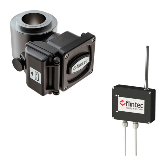
User Manual - CC1W 1. Product Description The CC1W is a wireless version of our CC1 pump off control load cell. The CC1W utilizes the same proven design attributes as the CC1. This includes a stainless steel body, hermetic sealing, with fatigue rating. The CC1W transmits polished rod load wirelessly, which solves the industry wide problem of cable failures. -
Page 4: Mounting Instructions
User Manual - CC1W 2. Mounting Instructions IMPORTANT The employees responsible for the equipment installation and verification must take into consideration all the actions concerning this subject specified in IEC 60079-14:2013 ed. 5.0 (electrical installations design, selection and erection) standard. In addition to general specifications associated with any system installed in hazardous locations, special attention should be paid for specific requirements regarding essential safety. - Page 5 User Manual - CC1W Base Unit Where there is no metallic surface to make use of the base units magnet, brackets, plates or other types of support can be used to suitably fasten the base to any structure. DIN rail mount Pole mount with u-bolt assembly IMPORTANT In order to achieve the best performance...
-
Page 6: Antenna Recommendations
User Manual - CC1W Antenna Recommendations Antenna Height Omni Directional Antenna CC1W base unit is equipped with The base unit antenna can be an Omni-directional antenna in positioned flexibly using the order to provide the widest possible antenna extension cable. signal coverage. - Page 7 User Manual - CC1W Enclosure Mounting V1.2 – ISSUED 17 AUG 2020 Page 7 of 22 DOC No. 0095771...
- Page 8 User Manual - CC1W SIGNAL CABLE COLOR CODE Excitation + / Vref + GREEN mV/V Signal + / mA + WHITE mV/V Signal - / mA - BLACK Excitation - / Vref - YELLOW Shield (NC) GRAY Optional analog VIOLET Ground POWER CABLE COLOR CODE...
-
Page 9: Remote Unit (Wireless Loadcell)
User Manual - CC1W Remote Unit (Wireless Loadcell) CC1W is mounted in the same way as other polished rod load cells. No special mounting procedure is required. IMPORTANT Position the remote unit (plastic enclosure at front of load cell) so that the best possible line of sight is achieved. -
Page 10: Battery Installation
User Manual - CC1W Battery Installation The CC1W is powered by a battery, positioned within the battery enclosure. Damaged or wet batteries MUST NOT be fitted. Damaged or wet batteries must be discarded and replaced. WARNING: The CC1W is certified for use with TADIRAN TL-5930/F. Make sure the battery cable tucks cleanly inside the compartment to prevent damage when the battery enclosure door is closed. -
Page 11: Equipment Maintenance
User Manual - CC1W 3. Equipment Maintenance The only live maintenance permitted for this product is replacement of the battery pack which must be done in non-hazardous areas. Repair is not permitted / la réparation n'est pas autorisée Health and safety standards in the workplace must be strictly observed for all personnel conducting maintenance tasks. -
Page 12: Operation
User Manual - CC1W 4. Operation 1. Disconnect or turn off power to the base unit. 2. Ensure the base antenna connected with RF filter. RF filter always mounted on the base as shown on pictures. The remote’s antenna is installed by the manufacturer; to preserve safety certifications, it is not intended to be removed. -
Page 13: Base Unit Wireless Channel Selection (If Needed)
User Manual - CC1W Base Unit Wireless Channel Selection (if needed) Remove the base top cover. Unscrew the 4 Phillips head screws attached to the flat base cover with the proper tool (manual Phillips screwdriver). WARNING: Gently lift the cover to prevent damage to the 3 LED light tubes attached to the cover V1.2 –... -
Page 14: Technical Specification
User Manual - CC1W 5. Technical Specification Standard Specifications 30k, 50k Rated Output mV/V 2.00 ± 0.5% mA (available) 4-20 Rated Position Output % FS (Stroke) ± 2 Nonlinearity % FS ± 0.25 Hysteresis % FS ± 0.25 Non-Repeatability % RO ±... -
Page 15: Markings
User Manual - CC1W 6. Markings Remote unit (transmitter) Equipment Group - All areas except mines Label Equipment category and environment - Gas, vapor, mist Explosion protection - Conformity with some of the IECs protection modes Protection type - Intrinsic security “ia” protection mode than mines. -
Page 16: Product Dimensions
User Manual - CC1W 7. Product Dimensions [inches] Remote unit (dimensions in V1.2 – ISSUED 17 AUG 2020 Page 16 of 22 DOC No. 0095771... - Page 17 User Manual - CC1W Base unit (receiver) V1.2 – ISSUED 17 AUG 2020 Page 17 of 22 DOC No. 0095771...
-
Page 18: Safety Information
User Manual - CC1W 8. Safety Information Intended Usage Operating temperatures cannot exceed 80°C or -55°C. Operation of the CC1W outside of the defined temperatures will result in none compliance of awarded safety certification. Avoid placement of the CCW1 radio device in areas of heating or cooling sources. The CC1W system works as a wireless network. - Page 19 User Manual - CC1W X Mark Conditions The capacitance of exposed isolated metal parts was found to be 53.9 pF. Static discharge - It is recommended that fitment and maintenance be carried out in electrostatic clothing, whilst wearing gloves and using insulating objects/tools. Cleaning should be carried out with a damp cloth.
- Page 20 User Manual - CC1W FCC Certification Statement Note: This equipment has been tested and found to comply with the limits for a Class A digital device, pursuant to part 15 of the FCC Rules. These limits are designed to provide reasonable protection against harmful interference when the equipment is operated in a commercial environment.
- Page 21 User Manual - CC1W ISED RSS-Gen Notice “This device complies with Industry Canada’s license-exempt RSSs. Operation is subject to the following two conditions: (1) This device may not cause interference; and (2) This device must accept any interference, including interference that may cause undesired operation of the device.”...
- Page 22 User Manual - CC1W Remote Unit: IC: 25535-CC1BRR Permitted Antennas • Yageo ANTX100P112B24553, maximum gain of +2.2dBi • Molex 1461870150, maximum gain of +3.0dBi FCC & ISED Canada RF Exposure Notice This device is intended to be mounted at a fixed location. This device is not intended to be operational while carried on a person.
Need help?
Do you have a question about the CC1W-30klb and is the answer not in the manual?
Questions and answers