Table of Contents
Advertisement
Lytx
Installation Instructions
(North America Edition)
Last updated: 6/18/2018
THE DEVICE SHOULD BE INSTALLED AND MAINTAINED BY QUALIFIED TECHNICIANS. Only a properly qualified technician
should install and maintain the ER-SV2 device. Any electrical work should be performed only by an ASE (minimum T6 &
L2), MECP or equivalent certified technician with an expertise in installing and troubleshooting advanced vehicle onboard
components including multiplexed circuits. Lytx, Inc. disclaims all responsibility for any damages arising from improper
installation and maintenance of the ER-SV2 device.
This guide is protected as confidential and proprietary information of Lytx, Inc. Copying and use of this guide for any
purpose other than installing ER-SV2 in vehicles of Lytx, Inc.'s customers is expressly prohibited. Information contained
in this guide was in effect as of the date set forth above and is subject to change without notice or liability. Lytx, Inc.
reserves the right to revise the information presented or to discontinue the production of parts described at any time.
©2018 Lytx, Inc. - Confidential & Proprietary.
®
ER-SV2 Event Recorder
Page 1 of 44
Advertisement
Table of Contents
Troubleshooting

Related Manuals for Lytx ER-SV2

Summary of Contents for Lytx ER-SV2
- Page 1 ER-SV2 in vehicles of Lytx, Inc.’s customers is expressly prohibited. Information contained in this guide was in effect as of the date set forth above and is subject to change without notice or liability. Lytx, Inc.
-
Page 2: Table Of Contents
Route the High-Speed Serial Cable V. Run Testing and Complete Installation Gauge the Voltage of the Wire Connections Test Event Creation and Upload Test Wire Connections and Settings in the Lytx Installation Tool Initiate Diagnostic Mode Complete Installation Conduct Final Checks... - Page 3 Mount the Remote Push Button Assign the Input in the Lytx Installation Tool Maintenance & Troubleshooting Maintenance Troubleshooting Installation Issues Contact Technical Support Troubleshooting Issues After Installation Initiate Diagnostic Mode Diagnostics and Troubleshooting Page 3 of 44 ©2018 Lytx, Inc. - Confidential & Proprietary.
-
Page 4: Safety Instructions
WARNING: All wires that carry electrical current to the Lytx device must be fused. Failure to fuse the power, ground, and ignition wires can lead to serious personal injury and/or prop- erty damage. -
Page 5: Adherence To Applicable Local, State And Federal Laws
(including poor lane markings, construction zones, dirt roads, heavy or complic- ated traffic, and curvy and winding roads), the Lytx Event Recorder may have limited to no functionality. The Lytx Event Recorder may not detect certain objects such as motorcyclists, bicyclists or pedestrians even in the most ideal conditions. -
Page 6: Canada - Industry Canada Notice
à l'intérieur et doit être tenu à l'écart des fenêtres afin de fournir un blindage maximal. Cet appareil numérique de la classe B est conforme à la norme NMB-003 du Canada. Suppliers Declaration of Conformance We, Lytx, Inc., hereby declare that the Manufacturer’s Contact: product listed below, to which this Declar- Lytx, Inc. -
Page 7: Device Installation Overview
Support Center at 866.910.0403 or email support@lytx.com immediately. Lytx recommends that you do not drive the vehicle until the malfunction is resolved. Lytx, Inc. disclaims all responsibility for any damages arising from improper installation and maintenance of the ER-SV2 device. -
Page 8: Materials
You are responsible for complying with such laws and regulations, and Lytx, Inc. does not accept responsibility for your failure to do 5. Use special tools and safety equipment to avoid serious personal injury and damage to components. -
Page 9: Required Tools
Two (2) T-27 security Torx screws Alcohol wipe One (1) T-8 security Torx screw J1939 CAN Coupler If you are missing any materials, contact the Lytx Technical Support Center at 866.910.0403 or email support@lytx.com to obtain the necessary materials before beginning installation. -
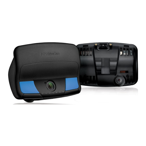
Page 10: Device Overview
4. USB Cable 5. High-Speed Serial Cable 6. Base Unit Cover 7. Serial number (on side of Base Unit) 8. Interior-facing lens 9. LED status lights 10. Manual record buttons Page 10 of 44 ©2018 Lytx, Inc. - Confidential & Proprietary. -
Page 11: Er-Sv2 Installation Procedures
ER-SV2 Installation Procedures Installation of the ER-SV2 event recorder consists of these main sections. Each section has its own subsections as well: I. Download and Install the Lytx Installation Tool II. Mount the Base Unit III. Mount the Bracket and Window Unit IV. -
Page 12: Instructions For Download And Installation
2. Go to My Learnings. Then go to My Learning Paths. 3. Browse and find the learning path, Lytx Installation Tool. Press Start. 4. Browse and find the course for "Lytx Installation Tool Download". Press Register. Then press Start. 5. Download the installation file to your computer. -
Page 13: Iii. Mount The Bracket And Window Unit
Mounting the bracket and event recorder consists of these subsections: 1. Review Mounting Location Guidelines a. Mounting Location Recommendations and Restrictions 2. Prepare the Mounting Location 3. Attach the Bracket and Window Unit Page 13 of 44 ©2018 Lytx, Inc. - Confidential & Proprietary. -
Page 14: Review Mounting Location Guidelines
To use the Window Unit to temporarily gauge the best position, first loosen the Torx screws so the Window Unit can rotate in the bracket. Then hold it up to the wind- shield. Page 14 of 44 ©2018 Lytx, Inc. - Confidential & Proprietary. - Page 15 The figures below provides Lytx’s recommendations for mounting the Window Unit on the vehicle windshield that work within the guidelines set forth by the U.S. Department of Trans- portation, Federal Motor Carrier Safety Administration (FMCSA)*.
-
Page 16: Prepare The Mounting Location
Turn on the wipers and rotate mirrors, sun visors, and other objects near the device to make sure they cannot block either lens. Page 16 of 44 ©2018 Lytx, Inc. - Confidential & Proprietary. -
Page 17: Attach The Bracket And Window Unit
Connecting the electrical wiring consists of these subsections: Wiring Safety Warnings Electrical Connection Overview Diagram Wiring and Wire Termination Suggestions Basic Event Recorder Electrical Connections Connect Turn Signals and Brake Inputs Page 17 of 44 ©2018 Lytx, Inc. - Confidential & Proprietary. -
Page 18: Wiring Safety Warnings
Never use plier tap products such as insulation displacement connectors (i.e. ScotchLoc connectors) when installing the ER-SV2. WARNING: Never wire the ER-SV2 device in a manner that shares a connection with another aftermarket product in the vehicle. Independent connections should always be used. -
Page 19: Electrical Connection Overview Diagram
Electrical Connection Overview Diagram Page 19 of 44 ©2018 Lytx, Inc. - Confidential & Proprietary. -
Page 20: Wiring And Wire Termination Suggestions
They cannot be used for constant power or ground. The Posi-Tap connectors must be the proper gauge size for the wire it's connecting to. Page 20 of 44 ©2018 Lytx, Inc. - Confidential & Proprietary. - Page 21 8. Quick slide/spade connectors: Quick slide/spade connectors may be used only if they are either properly insulated OR they are sealed with heat shrink. Otherwise, these may not be used. Page 21 of 44 ©2018 Lytx, Inc. - Confidential & Proprietary.
-
Page 22: Basic Event Recorder Electrical Connections
Hibernation mode when the ignition is switched off. This lead has a 1-amp inline fuse. 3. Black wire: Functions as ground. This lead has a 5-amp inline fuse. Page 22 of 44 ©2018 Lytx, Inc. - Confidential & Proprietary. - Page 23 This can give false ignition on/off signals. Connect the BLACK WIRE to a Good Solid Vehicle Ground CAUTION: This is a fused connection. Do NOT cut off or remove the inline fuse. Page 23 of 44 ©2018 Lytx, Inc. - Confidential & Proprietary.
-
Page 24: Connect Turn Signals And Brake Inputs
J1939 network without any puncture, cut, or splice into the vehicle cabling. Refer to the "Electrical Connection Overview Diagram" on page 19 for the following steps. Page 24 of 44 ©2018 Lytx, Inc. - Confidential & Proprietary. - Page 25 HI (Y) side and the green wire on the CAN-LO (G) side. Ensure that the wires are secured in the tabs provided and properly oriented. 5. Place the cap on the CAN Coupler. Page 25 of 44 ©2018 Lytx, Inc. - Confidential & Proprietary.
- Page 26 Connect to the Vehicle J1708 Network Before You Begin Lytx recommends using Posi-Tap connections to connect to the J1708 network. If necessary, ring terminal connections may be used instead. Refer to the manufacturer-specific connection guide for possible locations of the vehicle network bus.
-
Page 27: Route The High-Speed Serial Cable
2. Starting from below the dash near the kick panel, route the end of the cable up the door pillar underneath the vertical door/window trim to the top of the door pillar. Page 27 of 44 ©2018 Lytx, Inc. - Confidential & Proprietary. - Page 28 6. Make sure the cable is clear of any sharp edges, moving parts, and cannot get pinched in the door jamb. 7. Make sure the cable is tucked away and secured so that it cannot come loose. Lytx recommends using cable-ties at least every foot, or as necessary, along the route of the cable to secure it in place.
-
Page 29: Run Testing And Complete Installation
Completion of the installation consists of these subsections: Gauge the Voltage of the Wire Connections Test Event Creation and Upload Test Wire Connections and Settings in the Lytx Installation Tool Initiate Diagnostic Mode Complete Installation Conduct Final Checks Gauge the Voltage of the Wire Connections Using a voltmeter, check the wire connections on the Vehicle Interface Cable. -
Page 30: Test Wire Connections And Settings In The Lytx Installation Tool
Test Wire Connections and Settings in the Lytx Installation Tool Prior to Testing To test wire connections and settings, the Lytx Installation Tool must first be installed on your laptop. If this hasn't already be done, follow the instructions in "I. Download and Install the Lytx Installation Tool"... - Page 31 3. After completion, disconnect the micro USB cable. Camera Measurements While testing in the Lytx Installation Tool, you must take and enter the measurements below. Measurements must be entered in whole centimeters (cm). Tip: If you're measuring in inches (in), convert to cm using: # of in x 2.54 = # of cm. Convert any fractional inches to decimal first before calculating the cm.
- Page 32 Measure from the floor of the cab to the forward-facing lens. If needed, you can measure from the floor to the dash, then from the dash to the camera. c. Add the measurements together. Page 32 of 44 ©2018 Lytx, Inc. - Confidential & Proprietary.
-
Page 33: Initiate Diagnostic Mode
Troubleshooting in Diagnostic Mode If you run into any issues in Diagnostic Mode, take the troubleshooting steps in "Diagnostics and Troubleshooting" on page 42. If issues persist after troubleshooting, please contact the Lytx Technical Support Center at 866.910.0403 or email support@lytx.com. Complete Installation 1. -
Page 34: Conduct Final Checks
5. Keep this guide in a safe place for future use. Conduct Final Checks After installation of the ER-SV2 device but prior to any operation of the vehicle, check all vehicle system lights, signals, and any other devices (such as electronic log devices systems or CB radios) to make sure they are working properly. -
Page 35: Remote Push Button Installation Procedures
This is useful for drivers of larger vehicles in which the ER-SV2 event recorder is positioned out of reach of the driver's seat, preventing them from easily pushing one of the manual record buttons on the event recorder when seated in the driver's seat. -
Page 36: Assign The Input In The Lytx Installation Tool
Note: After assigning the Remote Push Button, the Lytx Installation Tool may take up to several minutes to detect the assignment. Please wait for detection before troubleshooting. Page 36 of 44... -
Page 37: Maintenance & Troubleshooting
After installation has been completed, Lytx recommends inspection and maintenance be performed every time normal preventative maintenance is performed on the vehicle and anytime the Lytx Vehicle Event Recorder or its wiring and electrical connections are moved, re-installed or otherwise altered from their initial installation. - Page 38 After the event is created, hold one of the manual record buttons for 10 seconds to attempt a forced check-in to Lytx. The LED status lights will light up and blink green one-by-one from the left to right until all are lit, indicating the check-in was successful.
- Page 39 J1708 backbone but to a stub. Try connecting to a different location on the J1708 network. The turn signal or brake Verify the inputs are correctly assigned in the Lytx Installation inputs aren't being Tool. Check the connection point and inspect the corresponding detected in the Lytx wiring for cuts or damage.
-
Page 40: Contact Technical Support
Lytx event recorders have built-in diagnostic tools to help troubleshoot issues you may exper- ience. If you're having issues with the ER-SV2 event recorder, initiate the device's Diagnostic Mode. In this mode, the device's LED status lights will help identify the specific component of the device that may be causing the issue. -
Page 41: Initiate Diagnostic Mode
Diagnostic Mode. Initiate Diagnostic Mode To initiate the Diagnostic Mode on the ER-SV2 device, you must first reboot the device. To reboot the ER-SV2 device, follow these steps: 1. Press and hold either of the blue manual record buttons on the Window Unit until the 3 center LED status lights turn blue (hold for about 30 seconds). -
Page 42: Diagnostics And Troubleshooting
The device will stay in Diagnostic Mode for 5 minutes. Pay attention to the LED status lights during this time. Color Status Green ● Error - requires ● troubleshooting (For LED 2 only) Error - requires Yellow troubleshooting ● Page 42 of 44 ©2018 Lytx, Inc. - Confidential & Proprietary. - Page 43 After the event is created, hold one of the manual record buttons for 10 seconds to attempt a forced check-in to Lytx. The LED status lights will light up and blink green one-by-one from the left to right until all are lit, indicating the check-in was successful.
- Page 44 Right turn signal Verify that the Right Turn Signal is properly assigned in the Lytx Installation Tool. Check the connection point and inspect the corresponding wiring for cuts or damage. Page 44 of 44 ©2018 Lytx, Inc. - Confidential & Proprietary.
Need help?
Do you have a question about the ER-SV2 and is the answer not in the manual?
Questions and answers