Table of Contents
Advertisement
Advertisement
Table of Contents

Related Manuals for Flux beamo


Summary of Contents for Flux beamo
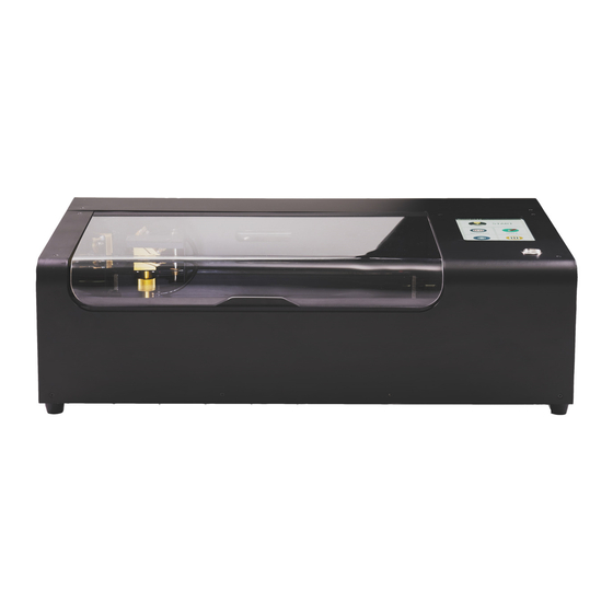
- Page 3 We proudly present beamo, the laser cutter that will help you create things that you'll love, and have fun during the process, too.
-
Page 4: Table Of Contents
TABLE OF CONTENTS Welcome 1.1 Using This User Manual..........09 1.2 CO2 Laser Basics............10 1.3 Safety & Conformity........... 12 Unboxing 2.1 What’s In The Box............17 2.2 Assembly..............20 2.3 Network Setup............21 2.4 Software Download & Setup........22 2.5 First Task..............24 Software Beam Studio 3.1 Software User Interface..........29 3.2 Touch Screen User Interface........32 3.3 Bitmap Engraving............33... - Page 5 TABLE OF CONTENTS Material Technique 4.1 Testing New Material..........41 4.2 Wood................. 42 4.3 Leather................43 4.4 Acrylic.................44 4.5 Paper................45 4.6 Glass................46 4.7 Metal................46 4.8 Other Safe Material............47 4.9 Dangerous Material............47 Project Ideas..............50 Maintenance & Care 6.1 Keep Everything Lubricated........52 6.2 Cleaning Of The Workarea.........53 6.3 Wiping The Lens............
- Page 6 7.6 Laser Head Did Not Return To Rear Left Corner..88 7.7 Camera Alignment Issue..........89 7.8 Camera Preview Speed Too Slow......89 7.9 Camera Preview Does Not Work.......90 7.10 Connection Issue............90 7.11 Software Quits Unexpectedly........94 Addtional Information 8.1 Technical Data............96 8.2 Storage and Transport..........96 8.3 FLUX Support.............97 8.4 Disassembling & Dismantling........97...
-
Page 9: Using This User Manual
No part of this manual may be reproduced, edited or modified in any form without the prior consent of FLUX Inc.. The rights for reproduction in any form are reserved. FLUX Inc. reserves the right to change specifications of the hardware and software de- scribed in the user manual at any time and without prior notice. -
Page 10: Co2 Laser Basics
1.2 CO2 LASER BASICS... -
Page 12: Safety & Conformity
1.3 SAFETY & CONFORMITY Be sure to read the following safety precautions carefully be- fore starting to operate beamo. beamo uses a high-power laser beam. Improper handling can result in fire, visual impairment, skin burns, or inhalation of toxic substances, and other personal safety hazards. - Page 13 1. The machine comes in 2 versions, 110V and 220V. Do not use a power source other than the AC rated voltage. If in doubt, contact FLUX Support. (110V: 100 - 127V / 220V: 200 - 240V) 2. Make sure that the grounding pin is properly connected. If...
- Page 14 Fire Safety 1. Do not put anything inside the machine that is not laser- compatible. Learn more about laser-compatible materials. 2. Do not stack materials; for example, do not attempt to cut two or more sheets of material at a time. 3.
- Page 15 Conformity The beamo unit is a Class 1 laser product containing an embed- ded Class 4 CO2 laser and a Class 1 laser diode. Because the Class 4 laser is fully contained in a Class 1 enclosure, this laser product is designated as a Class 1 laser product during all proce- dures of operation.
-
Page 17: What's In The Box
2.1 WHAT’S IN THE BOX 1. Place the box on the floor and open it. 2. Remove the packing foam ion the four corners and take the machine out of the box. Have two people lift it out of the box. - Page 18 3. Open the lid and take out the vent hose, then take out the Accessory Kit. 4. Content of the Accessory Kit: : ① Wi-Fi dongle ② lubricant ③ duct clamp ④ double-sided tape ⑤ power cord ⑥ small wrenches ⑦ hex key ⑧ funnel ⑨ sample material...
- Page 19 5. Front view: ① laser head ② focus bar ③ honeycomb plate ④ touchscreen ⑤ power button ⑥ transparent lid ⑥ ④ ⑤ ① ② ③ 6. Rear view: ① USB ports ② Ethernet port ③ power connector ④ exhaust fan...
-
Page 20: Assembly
3. Use the duct provided. Slide the duct clamp around the bigger end of the duct then install the duct and clamp over the fan exhaust on the back of your beamo. Use the small wrench to tighten the clamp. -
Page 21: Network Setup
2.3 NETWORK SETUP 1. Press the power button to turn the machine on. It takes about 1 minute to start up. 2. On the touchscreen, tap on Settings > Internet > Settings then select a Wi-Fi network and enter its password. 3. -
Page 22: Software Download & Setup
Beam Studio app into the Application folder next to it. Run the Beam Studio in the “Application” folder. 2. A language dialog will appear when running Beam Studio for the first time. Select English > FLUX beamo. Troubleshooting: Software Unexpectedly Quits (p.94) - Page 23 3. Fill in your beamo’s IP address in the text box and click Start 4. Go to menu > Machine or click on the camera icon at the bottom left corner to check if your beamo’s name can be found.
-
Page 24: First Task
2.5 FIRST TASK 1. Adjusting Focus Place a workpiece in the machine. Rotate the focus bar (acrylic bar) downward until it is vertical. Loosen the laser head focus ring and lower the laser head until the focus bar rests on the workpiece. Tighten the laser head focus ring, and rotate the focus bar upwards until it is horizontal. - Page 25 2. Camera Preview In Beam Studio, click on the camera icon ( ) at the bottom left and select your machine from the list. The preview mode is ready when the mouse cursor becomes a camera ( ).Click and drag your mouse cursor to preview the work area. Click again or press ESC to leave preview mode.
- Page 26 2. Import Test File Click on menu > File > Samples > Example of beamo. Place the image at the ideal spot. Click on Export, select your machine from the list, and click Start to start the task.
- Page 27 3. Test Result If the result is too light or blurry, please check if the focus is just right. If the focus is right but the result is poor, please recheck the optical path. See “Optical Path Adjustment” (p.600000). If the position of the result varies with the camera preview, please recheck the focus or see “Camera Alignment Issue”...
-
Page 29: Software User Interface
3.1 SOFTWARE USER INTERFACE Ⓐ Ⓒ Ⓑ Ⓓ A. Object Placement : Zoom in and zoom out : Group multiple items together : Ungroup items : Align multiple items horizontally : Align multiple items vertically : Distribute selected items horizontally between the left and right borders : Distribute all selected items vertically between the top and bottom borders... - Page 30 : Reflect an object across a horizontal axis : Reflect an object across a vertical axis : Export the laser job to your beamo B. Object Editing : Selection tool : Import JPG/PNG/SVG/DXF files. You can also...
- Page 31 C. Layer Management : Create and name a new layer : Delete selected layer : Rename selected layer : Sequence arrangement, the working sequence will be from top to bottom D. Power and Speed Setting Parameters for commonly used material can be found i n t h e "...
-
Page 32: Touchscreen User Interface
3.2 TOUCHSCREEN USER INTERFACE Home Connected to Wi-Fi Access previous laser jobs Hardware maintenance Activate Smart Trace Online database Machine settings... -
Page 33: Bitmap Engraving
3.3 BITMAP ENGRAVING Bitmap and vector are two different types of digital image files. Bitmap is an image type that consist of numerous square pixels. Bitmap files are rich in details which are mostly suitable for photography or digital applications. However, the quality is related to the resolution so the image can get jagged or blurry when resized. -
Page 34: Vector Engraving
m o n o c h r o m i c , w h i c h i s o p t i m i z e d f o r b u i l t - i n "Monochromatic Engraving" parameters. When "Shading" is enabled, images will be transfor med into greyscale, w h i c h i s o p t i m i z e d f o r b u i l t - i n "... -
Page 35: Comparison Between Bitmap & Vector Format
3.5 COMPARISON BETWEEN BITMAP AND VECTOR FORMAT Bitmap Vector Format JPG / PNG SVG / DXF infill engraving outline engraving/ Usage (monochrome/shading) cutting Select vector format for all cutting jobs. 3.6 LAYER SETTING You can set the layering style by "Layer", "Color" or "Single Layer"... -
Page 36: Recommended Design Software
3.8 RECOMMENDED DESIGN SOFTWARE A u t o C A D i s a C A D s o f t w a re s p e c i a l i z e d i n a c c u r a t e dimensions, solids and more. -
Page 37: Smart Trace
The process is quite simple, first you draw something on paper and the camera in beamo will convert your drawing to a digital file, you can then print the file on the materials of your choice. - Page 38 3. Click "Trace Image" and drag a square around the artwork that you want to trace. You’ll see a preview of what your beamo will engrave. Anything in black will be engraved, and nothing else will be. 4. Darken or remove small details like dirt and noise by...
- Page 39 5. Click "Preview" and when your trace looks ready, click "Apply". 6. Set the power and speed and start the laser job. Prepare to see your newly digitized artwork!
-
Page 41: Testing New Material
4.1 TESTING NEW MATERIALS To test different speed and power combinations on a new material, import the "Material Testing Suite" from the menu > File > Samples. -
Page 42: Wood
4.2 WOOD Types of Wood • Medium-density Fiberboard (MDF) MDF is a wood product made by wood fibers and resin binder formed under high temperature and pressure. The resin binder has a significant effect on the fume generated during laser process. Low formaldehyde MDF is recommended to reduce harmful fumes. -
Page 43: Leather
How To Prevent Burn Marks On Wood Cover the surface with masking tape prior to printing, or remove the marks with sandpaper. The alternative is to slightly wet the wood, but it might cause bumps on the surface. How To Reduce Burn Edge On Wood Clean the edges with alcohol or soapy water, or choose wood with lower density, so the cutting speed can be faster, leaving lighter edge marks. -
Page 44: Acrylic
b y t a n n i n g , t h a t i s , t h e p a r t o f t h e l e a t h e r w h i c h i s similar to the non-woven material. -
Page 45: Paper
other transparent plastic materials (i.e. PVC or PC) that are not suitable for laser processing. When processed on, the edges of the acrylic are sharp and clear. If you see yellowish burn marks, the material is not acrylic. However, no burn marks doesn’t indicate that it is acrylic. Scratches on Acrylic Scratches can be removed with plastic polish. -
Page 46: Glass
Corrugated Cardboard When cutting corrugated paper, the cardboard might catch on fire due to the misfocus on the downward layer. Spray the board with water to reduce the chance of burning. 4.6 GLASS Glass cracks easily, so the laser power should not be too powerful. -
Page 47: Other Safe Material
4.8 OTHER SAFE MATERIALS Stone, cement, EVA foam, cotton, linen material, etc. 4.9 DANGEROUS MATERIALS • PVC PVC is a common material that cannot be laser processed. When burned, PVC produces HCl (hydrochloric acid gas) that will harm the lungs and corrode machine parts. - Page 48 • Plastics With Chlorine, Benzene, Ammonia, Fluorine, Phenol, Aldehyde in its Scientific Name or With A Hexagonal Benzene Ring in its Molecular Formula When burning plastic molecules with these elements or organic structures, the chances of producing carcinogens and toxic substances are extremely high. Laser processing is not recommended.
-
Page 50: Project Ideas
5.1 INSIPIRATIONS https://pse.is/KFDPQ • Pinterest Idea Board https://pse.is/JXRR5 Search for "laser engraving" on Pinterest for more ideas! • Ponoko Laser Engraving Ideas https://pse.is/HQARL 5.2 VECTOR FILES • The Noun Projects https://thenounproject.com/ • Freepik http://freepik.com/ 5.3 CUTTING FILES • DXF Projects https://dxfprojects.com/ •... -
Page 52: Keep Everything Lubricated
6.1 KEEP EVERYTHING LUBRICATED Clean and lubricate the guiding rods and rail periodically can extend the lifetime of the moving parts. The frequency recom- mended is once every 1 - 2 weeks. 1. Wipe away the oil grease on the guiding rodsand rail using a paper towel. -
Page 53: Cleaning Of The Workarea
6.2 CLEANING OF THE WORKAREA Remove leftover cutting and engraving bits from the workarea whenever there is a buildup. A buildup of leftover bits can create a fire hazard. 1. To remove the honeycomb plate, first move the laser head to the top left corner, lift the honeycomb plate slightly and slides it toward you. -
Page 54: Wiping The Lens
6.3 WIPING THE LENS After every 40 hours of working, use lens wipes or wet cotton swabs to clean the lens and mirrors. Do not rub the mirrors fiercely to prevent damage of the coating on the mirrors. This will keep the unit working properlyand prevent permanent damage to your unit. - Page 55 The focus lens is inside the lens holder under the third reflecting mirror. Lower down the honeycomb plate or remove it to make room for later procedure. Rotate the lens holder ring clockwise to release and remove the lens holder. ▲...
-
Page 56: Water Cooler Maintenance
6.4 WATER COOLER MAINTENANCE Adding Water When you see a low water level or a "#900 Cooler Off" dialog appears on the touchscreen. Please add water to the water tank. 1. Unplug the machine. 2. Remove the back lid by unscrewing the 6 star screws with the hex key in the Accessory Kit. - Page 57 4. Fill up the tank using distilled water. Watch the water level carefully to prevent from spilling over. Seal the tank when the water level reaches 80% full. Changing Water It is recommended that the water should be changed once every 3 months.
- Page 58 3. Remove the laser head, plug the air outlet into the water pipe. Go to touchscreen and press Action > Air Pump, the water will be blown out from the other end. Press "Air Pump" again when water is drained from the water tank and hose.
-
Page 59: Optical Path Alignment
Accesory Kit: ② hex key ③ small wrench ④ tape Prepare On Your Own: ① 2.5mm Allen key Safety Precautions 1. Keep the lid shut when pressing "Laser Pulse". 2. If you hear a loud cracking sound, stop operating and shut down the power immediately. Contact FLUX Support. - Page 60 Accessory Kit. There are three sets of reflecting mirrors and one set of focusing lens in beamo. • First reflecting mirror is located on the left side of the laser tube when facing the machine.
- Page 61 • Third reflecting mirror is located on the rail of the X-axis. • Focusing lens is located inside the lens holder underneath the third mirror. First Reflecting Mirror Goal: Make the 2 dots shot from the top-left and the bottom-left overlap. 1.
- Page 62 5. Manually move the laser head to the bottom-left. 6. Close the lid and press "Laser Pulse". 7. Open the door and check if the second beam is overlapping with the first one. If not, adjust the screws behind the first mirror. If the dot shot from the bottom left corner is not found on the tape, it means the optical path is very much mis- aligned.
- Page 63 left position. Make sure the dots of the top-left and the middle-left overlaps, then go back to the original top-left and bottom-left adjustment. 8. The screws behind the first mirror control the mirror angle shown in the picture below. Release the nut on the screw, rotate the screw for the desired direction and test the dot position until the two dot overlaps.
- Page 64 Second Reflecting Mirror Goal: Make the 2 dots shot from the middle-left and the middle-right overlap. 1. Put a piece of tape on the metal ring of the third mirror. 2. Move the laser head to the mid-left positon manually. Close the lid and press "Laser Pulse".
- Page 65 4. Move the laser head to the middle-right position manually. Close the lid and press "Laser Pulse". 5. Open the lid and check if the second dot overlaps with the first one. If not, adjust the screws behind the second mirror. If the dot shot from the middle-right corner is not found on the tape, it means the optical path is very much misaligned.
- Page 66 6. The screws behind the second mirror control the mirror angle shown in the picture below. Release the nut on the screw, rotate the screw for the desired direction and test the shot position until the two shots overlaps. Tighten the nut slightly back to its position when the adjustment is done.
- Page 67 3. Release the 4 hex socket head screws with a 2.5mm Allen key. 4. Move the laser head forward or backward related to the rail. Then tighten the 4 screws back. 5. Press "Laser Pulse" and check if the dot landed on the vertical center line of the ring.
- Page 68 8. Check if the dot overlaps or lands above the center line. The first and second mirrors might require readjustments if the position of the laser tube holder is widely adjusted. Third Reflecting Mirror Goal: Dot be made on the center of the laser beam outlet. 1.
- Page 69 third mirror need to be adjusted. 5. The screws behind the third mirror control the mirror angle which is shown in the picture below. Release the nust on the screws, rotate the screws for the desired direction until the two dots overlap. Tighten the nut slightly back to its position when the adjustment is done.
- Page 70 The power of the laser can now be distributed evenly to any spot of the workarea after the adjustments above. The performance should meet the needs of regular operation. Make sure you run "Camera Calibration" again after the optical adjustment. If the verticality of the optical path is required in specific applications, then steps below can be carried out for advanced adjustments.
- Page 71 4. Release three nuts behind the third mirror. Rotate the three screw equally so the mirror can move forward or backward in a paralleled direction. Make the gap between the metal pieces be X mm. 5. Release the lens holder ring by rotating clockwise and lowering the lens holder to the mid-height.
- Page 72 9. Close the door and press "Laser Pulse". Open the door and check the dot. There are three scenarios: • The shot is in the center of the circle. Indicating the optical path is already vertical. • The dot is on the right side of the circle. Indicating the optical path has an angle which comes from the top-right and exit to the bottom-left.
-
Page 73: Laser Tube Replacement
6.6 LASER TUBE REPLACEMENT Tools Accessory Kit: ① little wrench ② funnel Laser Tube Box: ⑧ laser tube hose plug ⑥ cable ties Prepare On Your Own: ③ Philips screw driver ⑤ diagonal pliers ④ needle-nose pliers ⑩ water container ⑨ towel Unplug power before operation. - Page 74 There are two ends on a laser tube. The one with the red wire which is closer to the touch screen is called the high-voltage side. The other next to the first mirror is called the low voltage side. ▲ ▲...
- Page 75 4. Remove the screws of the tube holder on both sides. 5. Use pliers to move the hose clamp away from the laser tube.
- Page 76 6. Take the laser tube out of the chassis and place the low-voltage side above a container. 7. Disconnect the hose from the tube and drain the water. Clog the hose by a plug when done.
- Page 77 8. Place a towel on the high-voltage side. 9. Cut the cable tie on the end of the hose with diagonal pliers or scissors.
- Page 78 Pull off the hose and clog the end. Avoid spilling water into the machine. If it happens, wipe away the moisture and wait till the machine entirely dries up before operating. The laser tube is now fully disconnected and can be entirely removed.
- Page 79 Place the new laser tube and connect the hoses on both ends. Zip the high-voltage end by a cable tie and clamp the other end using the original metal hose clamp. ▲ Zip the high-voltage end by a cable tie...
- Page 80 ▲ clamp the low-voltage end using the original metal hose clamp Release the metal clamp slowly to prevent the reaction force from damaging the laser tube. Reconnect the white connector on the high- voltage side. Plug in the wire to the terminal on the low-voltage side and make sure the wire get clamped firmly and does not fell off.
- Page 81 ▲ check the wire if firmly clamped by the terminal Place the laser tube into the chassis. Make sure the gap is wider than a finger on both ends of the tube. The terminal on the laser tube which connected to the thick red wire should point upward.
- Page 82 Make sure everything is properly installed. Turn on the machine when ready. Do not touch the area near the high voltage side on the tube to prevent electric shock. Press "Maintain" and the laser head will go to home position. Press "Pump" and the cooling water will be pumped into the laser tube.
- Page 83 ▲ use the little wrench to open the tank Repeat Step 11 and 12 until the level of the tank no longer goes down. Then the replacement is complete.
-
Page 85: No Laser Beam Output
7.1 NO LASER BEAM OUTPUT If there is no laser beam output when beamo is running and making a loud cracking sound, it indicates the tube is broken. Please stop operating the machine to prevent further hardware failure. If you do not hear the cracking sound, please check the following: 1. -
Page 86: Cut Did Not Go Through Material
3. Check if the lens or mirrors are dirty or damaged. 4. Check if the optical path is aligned. 5. If the solutions above didn’t work, please contact FLUX Support. 7.3 #900 COOLER OFF 1. If you see a "#900 Cooler Off" dialog appears on the touchscreen, press "Continue". -
Page 87: 901 Door Opened
7.4 #901 DOOR OPENED If the base is detached, install the base back first. 1. Go to touchscreen > Maintain, observe the icon on the top right corner. Check if the door icon is changed to “closed” when the front door is closed. If the icon is changed, the machine should operate normally. -
Page 88: 902 Overheated
5°C- 35°C (41°F - 95°F). 3. If there is a huge difference between the room temperature and the temperature shown on the touch screen, please contact FLUX Support. 7.6 THE LASER HEAD DOESN’T RETURN TO REAR LEFT CORNER 1. -
Page 89: Camera Alignment Issue
(like the image in Step 1). 4. Start filming and repeat Step 1 and 2, send the video to FLUX Support. 7.7 CAMERA ALIGNMENT ISSUE 1. Run camera calibration in software: Beam Studio >... -
Page 90: Camera Preview Does Not Work
Please refer to 7.8 Camera Preview Speed Is Too Slow (p.89). 4. If you see a question mark icon, it means the camera is not functioning. Please contact FLUX Support. 7.10 CONNECTION ISSUE No Wi-Fi Found 1. Make sure the Wi-Fi dongle is fully plugged in. - Page 91 2. The encryption mode can be set in the Wi-Fi router administration interface. If the router doesn’t support WPA2 and you need help picking out the right router, please contact FLUX Support. Machine Doesn’t Appear In The Software 1. Go to touchscreen > Settings > Internet and confirm the machine IP address.
- Page 92 1. Go to software Beam Studio > Menu > Machines > Test Network Settings 2. Fill in the Target device IP Address column with the machine IP address.
- Page 93 >95%, the Average Response Time should be <100ms. If the machine IP address is keyed in but the machine is still not found, please update the software to the latest version. If the connection issue persists, please contact FLUX Support.
-
Page 94: Software Quits Unexpectedly
Windows Update KB2670838. • macOS Please update your OS to macOS 10.14 (Mojave) or above. Previous OS versions might have compatibility issues. • Linux Due to numerous types of systems, please provide the software log to FLUX Support. -
Page 96: Technical Data
• To store your beamo for a long period of time, it must be packed in its original packaging and not be exposed to high temperature and humidity fluctuations. -
Page 97: Flux Support
8.4 DISASSEMBLING & DISMANTLING beamo can be disposed of as a complete device. You do not have to disassemble or dismantle the unit before disposal. Only the cables and ventilation hoses can be handed over separately from your beamo to the electrical equipment collection unit.
Need help?
Do you have a question about the beamo and is the answer not in the manual?
Questions and answers