Subscribe to Our Youtube Channel
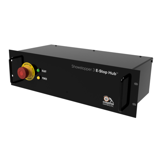
Summary of Contents for Creative Conners SHOWSTOPPER 3 E-STOP HUB
- Page 1 SHOWSTOPPER 3 E-STOP HUB TM REFERENCE MANUAL V2 Copyright 2020, Creative Conners, Inc. ...
- Page 2 ...
-
Page 3: Table Of Contents
TABLE OF CONTENTS GETTING STARTED 1 WHAT’S IN THE BOX? 1 FEATURES 2 INSTALLATION 3 MAKING THE CONNECTIONS 3 INPUT POWER 3 SHOWSTOPPER E-STOP OUTPUT 3 ACCESSORY INPUT/OUTPUT 3 TROUBLESHOOTING 5 When the Green and Amber lights are illuminated, you are ready to Make It Move! 5 ... - Page 4 ...
-
Page 5: Getting Started
Showstopper 3 E-Stop Hub expands the capabilities of your Showstopper 3 Base allowing 10 additional machines to be connected to your Emergency Stop Network. In order to use a Showstopper 3 E-Stop Hub, you will also need a Showstopper 3 Base to power your E-Stop Hub. This manual will guide you through: ... -
Page 6: Features
Green to indicate that all e-stops on the network have been disengaged and the Showstopper E-Stop Hub is ready for operation. b. Amber to indicate the Showstopper 3 E-Stop Hub has power. 1. Input Power - 120VAC, 1.4A IEC Socket ... -
Page 7: Installation
Published 4-14-20 INSTALLATION The Showstopper 3 E-Stop Hub is intended to be rack mounted in any standard 19” rack. Feel free to install it along with other Showstopper devices, a rack PC, a storage drawer for the Showstopper 3 Consolette or in racks with your Stagehand controllers. It can also sit on the operator desk or on top ... - Page 8 Showstopper 3 E-Stop Hub Reference Manual Published 4-14-20 end of the chain, you must have a terminator to complete the e-stop circuit. Make sure that any Accessory Output not connected to a device has a terminator. Below is the pin-out for the Showstopper Accessory output: ...
-
Page 9: Troubleshooting
Published 4-14-20 TROUBLESHOOTING The face of the Showstopper 3 E-Stop Hub has 2 indicator lights on the faceplate and one indicator light on the red mushroom button to help determine the state of the system. The chart below should help you diagnose any issues. ... -
Page 10: Technical Support
Showstopper 3 E-Stop Hub Reference Manual Published 4-14-20 TECHNICAL SUPPORT If you get stuck, we’re here to help. The best way to get in touch with a tech expert is via email - even during normal business hours - because most days we are spread around the shop and may not be ... -
Page 11: Specifications
Showstopper 3 E-Stop Hub Reference Manual Published 4-14-20 SPECIFICATIONS PHYSICAL SPECIFICATIONS The Showstopper 3 E-Stop Hub is packaged in a standard 19” x 3U rackmount case. The overall dimensions are: 17”W x 8”D x 5-1/8”H. ELECTRICAL SPECIFICATIONS Description ... -
Page 12: Drawings
Showstopper 3 E-Stop Hub Reference Manual Published 4-14-20 DRAWINGS OVERVIEW DRAWING Page 8 of 9 ... -
Page 13: Wiring Diagram
Showstopper 3 E-Stop Hub Reference Manual Published 4-14-20 WIRING DIAGRAM Page 9 of 9 ...


Need help?
Do you have a question about the SHOWSTOPPER 3 E-STOP HUB and is the answer not in the manual?
Questions and answers