Table of Contents
Advertisement
Quick Links
Advertisement
Table of Contents

Subscribe to Our Youtube Channel
Related Manuals for Creative Conners SHOWSTOPPER 3 REMOTE


Summary of Contents for Creative Conners SHOWSTOPPER 3 REMOTE
- Page 1 Creative Conners, Inc SHOWSTOPPER 3 REMOTE ™ REFERENCE MANUAL V1.0 ...
- Page 2 ...
-
Page 3: Table Of Contents
CONTENTS GETTING STARTED 3 What’s included 3 Features 3 INSTALLATION 3 POWERING UP 3 OPERATION 4 TROUBLESHOOTING 5 Common Problems 5 Technical Support 5 SPECIFICATIONS 6 Electrical Specifications 6 Drawings 7 ... -
Page 4: Getting Started
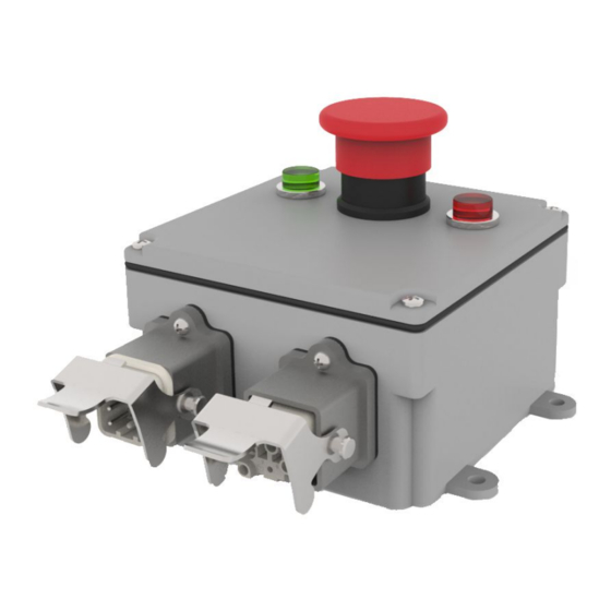
In the box you will find only the Showstopper 3 Remote. FEATURES The Showstopper 3 Remote is a 4” x 4” x 2 ½” box with 4 mounting holes. It has 1 Showstopper Accessory input and 1 Accessory output. On the face, there are two indicator lights and a standard ... -
Page 5: Operation
connected and turned on, you should make sure that no emergency stop button in the system is engaged. If power is connected and no E-stop is engaged, the green indicator light should be illuminated. OPERATION To operate the Showstopper Remote you will need to make sure it is powered. There are two indicator lights on the face of the remote. -
Page 6: Troubleshooting
TROUBLESHOOTING When encountering an issue with the Showstopper Remote the first thing to check would be to make sure that all cables are properly plugged into their respective receivers. Once that has been checked, the next step would be to make sure that power is turned on. If power is turned on and all cables are connected properly then it would be best to make sure no emergency stop button in the system is ... -
Page 7: Technical Support
Condition Remedy No indicators illuminated Check mains power Confirm no E-stop is activated Terminator isn’t connected Red indicator Local E-stop is activated Green indicator Ready to Make It Move! TECHNICAL SUPPORT Despite our best efforts and intentions to provide reliable equipment and clear instructions, there may come a time that you need more direct, personal help. -
Page 8: Specifications
SPECIFICATIONS ELECTRICAL SPECIFICATIONS Description Value Accessory Input 24VDC Accessory Output 24VDC ... -
Page 9: Drawings
DRAWINGS Dimensioned Drawing Schematic ...
Need help?
Do you have a question about the SHOWSTOPPER 3 REMOTE and is the answer not in the manual?
Questions and answers