Table of Contents
Advertisement
Quick Links
Advertisement
Table of Contents

Related Manuals for Creative Conners Stagehand Pro 3


Summary of Contents for Creative Conners Stagehand Pro 3
- Page 1 STAGEHAND PRO 3 REFERENCE MANUAL 1.1 Copyright 2020, Creative Conners, Inc.
- Page 2 Stagehand Pro 3 Reference Manual, 11-20 Index...
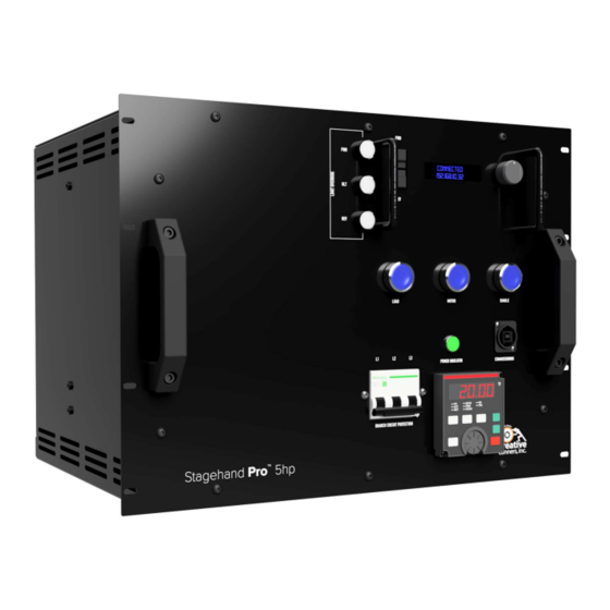
- Page 3 Stagehand Pro 3 Reference Manual, 11-20 Index GETTING STARTED What’s in the box Stagehand Pro 3 Features Forward and reverse jog buttons Knob OLED status display Limit switch override buttons - New! Brake test buttons Mains power indicator Branch circuit protection breaker - New!
- Page 4 Stagehand Pro 3 Reference Manual, 11-20 Index Motor and Brake Motor Motor Brake Load Brake Signal Ultimate Limit Reverse Limit Forward Limit Limit Wiring Strategies Speed Encoder Position Encoder Encoder Wiring Strategies Single encoder Dual encoders Ethernet Showstopper OPERATION Manual Operation...
- Page 5 Stagehand Pro 3 Reference Manual, 11-20 Index Brake Fault Emergency Stop Electrical monitor Parameter configuration Faults history Override Limits Brake Testing Connecting to Spikemark Setting the IP Address Setting the Subnet Mask Auto-Tuning Within Spikemark VFD Keypad Parameter Configuration Keypad...
- Page 6 Stagehand Pro 3 Reference Manual, 11-20 Index Phone Email SPECIFICATIONS Physical Specifications Electrical Specifications Mitsubishi VFD Parameters PLC Ladder Logic Wiring Diagram...
-
Page 7: Getting Started
Stagehand Pro 3 Features The Stagehand Pro 3 is an evolution of our Stagehand Pro controller. It shares many of the functional traits with its predecessor while offering a few key improvements. Let’s take a look: Page 1 of 56... - Page 8 Stagehand Pro 3 Reference Manual, 11-20 Forward and reverse jog buttons Press and hold, then turn the speed knob, to manually move the motor Knob When used with the jog buttons, the knob will adjust speed from 0%-100%. It doesn’t like to be spun super-fast, slow and steady is the best method.
- Page 9 Mains power indicator The power indicator glows when the circuit feeding the Stagehand Pro 3 is energized. Pro Tip: this indicator is connected to input phases X & Y only. It’s possible that you could be missing the Z input phase.
- Page 10 Stagehand Pro 3 Reference Manual, 11-20 Rack mounting - New! The Stagehand Pro 3 case is now made exclusively for rack mounting. Since 2013, when the Stagehand Pro was introduced, we heard from many customers that wanted an easier rack-mounting solution than was possible with our original case design.
- Page 11 Stagehand Pro 3 Reference Manual, 11-20 Pro Tip - In the Stagehand Pro 3, the safety relay is powered by the incoming 24VDC e-stop signal but the large power contactors draw their current from the internal power supply. This greatly reduces the electrical load on the Showstopper 3 Base or Hub.
-
Page 12: Installation
More details follow later in this manual to explain the process. INSTALLATION The Stagehand Pro 3 is designed to mount in a standard 19” vertical equipment rack. Use the included rackmount screws (qty 8) to fasten the controller into an equipment rack. -
Page 13: Input Power
After the Stagehand is installed, it is time to power it up and get your machine spinning. The Stagehand Pro 3 requires a 30-amp, 200VAC-240VAC, 3-phase, 4-wire circuit (3 hot legs and a ground). The Stagehand Pro 3 is equipped with a circuit breaker on the front panel. Flip the breaker OFF before applying power. - Page 14 (ILME CXF-4/8 or compatible). Before we dive into the details of the pin-out, we should clarify what these three power sources are and why they exist. Below is a picture of Creative Conners’ Spotline Hoist which serves as a nice example of a typical machine that needs all three power sources.
- Page 15 The motor brake uses the mechanical advantage of the speed reducer (aka gearbox) to increase its holding ability. The Stagehand Pro 3 expects that the motor brake will be fully released within 60ms of receiving power.
- Page 16 Stagehand Pro 3 Reference Manual, 11-20 brake fails, a brake on the load side of the machine will be able to stop a falling load. The Stagehand Pro 3 expects that the load brake will be fully released within 500ms of receiving power.
- Page 17 Stagehand Pro 3 Reference Manual, 11-20 reduce the time it takes to engage the brake. If you are using a load brake you should use fast-brake switching. It is important to hook up the correct brake to the designated terminals of the connector. Load brakes are typically much slower to respond than motor brakes because of their necessary size.
- Page 18 Stagehand Pro 3 Reference Manual, 11-20 Ultimate Limit A pair of normally-closed (N.C.) switches can be wired in series to this pair of terminals to provide protection against Forward and Reverse Limit switch failures. Typically, an Ultimate Limit switch is physically positioned just beyond both the Forward and Reverse Limit switch.
- Page 19 A set of quadrature signals used by the Variable Frequency Drive (VFD) to accurately regulate speed. Unlike the Stagehand Classic controller, the Stagehand Pro 3 requires a motor-mounted encoder for speed regulation. This same encoder may be wired for both speed and position data, but only if that encoder is mounted on the motor prior to the speed reducer.
- Page 20 Stagehand Pro 3 Reference Manual, 11-20 Encoder signal is missing or faulty, the VFD will enter a fault condition and the Stagehand won’t allow motion until the encoder is repaired. This feature is vitally important in lifting applications so that the Stagehand can detect a free-falling load and engage the mechanical safety brakes.
- Page 21 Stagehand Pro 3 Reference Manual, 11-20 Single encoder Dual encoders Page 15 of 56...
- Page 22 Stagehand Pro 3 Reference Manual, 11-20 Ethernet Page 16 of 56...
-
Page 23: Operation
Below is the pin-out for the Showstopper Emergency Stop input: OPERATION Once all of your connections are made, either by plugging in a pre-wired Creative Conners machine or by wiring up your own machine, the next step is to test the basic machine functions with the Stagehand. -
Page 24: Manual Operation
Stagehand Pro 3 Reference Manual, 11-20 Manual Operation Before you can write complex cues in Spikemark, let’s make sure the machine runs fine with when jogging it manually using the buttons and knobs on the face of the Stagehand. ● Release the Emergency Stop button on your Showstopper ●... - Page 25 Understanding the Status Displays The Stagehand Pro 3 has two status displays: one towards the top for the motion controller, and a second at the bottom for the VFD. Each display has different, but sometimes complementary information to convey.
-
Page 26: Motion Controller
Stagehand Pro 3 Reference Manual, 11-20 Motion Controller The two-line alphanumeric display on the Stagehand Pro motion controller uses OLED technology to make it easy to read backstage without a distracting backlight. It also has excellent viewing angles, making it easier for you and other operators to see status information at a glance. The Stagehand is... - Page 27 Stagehand Pro 3 Reference Manual, 11-20 Limits When a Forward, Reverse, or Ultimate Limit is struck the top line of the display will flash an appropriate fault message in rotation with any other fault messages. If you strike a directional limit switch, either forward or reverse, you will have to run the motor in the opposite direction to clear the fault message.
- Page 28 Stagehand Pro 3 Reference Manual, 11-20 Emergency Stop When the Emergency Stop circuit is activated, or unplugged, the Emergency Stop fault message will be added to the flashing fault messages. Any motion that was occurring when the Emergency Stop was detected will be stopped. To clear the fault, release the Emergency Stop button on the Showstopper.
- Page 29 Stagehand Pro 3 Reference Manual, 11-20 Page 23 of 56...
- Page 30 Stagehand Pro 3 Reference Manual, 11-20 Page 24 of 56...
- Page 31 The Limit Override buttons on the face of the Stagehand Pro 3 allow you to do just that. Press and hold the corresponding button and you can drive beyond an engaged limit.
-
Page 32: Brake Testing
Stagehand Pro 3 Reference Manual, 11-20 Brake Testing The Stagehand Pro can control two safety brakes for use in hoisting applications. The Stagehand Pro will internally check the electronic systems to insure the brake circuits are working properly before releasing either the motor brake or the load brake to prevent dropping a suspended piece of scenery. - Page 33 Stagehand Pro 3 Reference Manual, 11-20 ● While holding the Brake Test Button, press the Load Brake button. This will manually release the Load Brake. The Motor Brake should still be engaged and will hold the load. If the suspended scenery slips down, release the Load Brake button immediately. Since the Motor Brake did not hold the load as expected, that brake has failed.
- Page 34 Stagehand Pro 3 Reference Manual, 11-20 ● Provided the Motor Brake passed the functional test, release the Load Brake button. ● While holding the Brake Test Button, press the Motor Brake button. This will manually release the Motor Brake. The Load Brake should still be engaged and will hold the load. If the suspended scenery slips down, release the Motor Brake button immediately.
-
Page 35: Setting The Ip Address
Stagehand Pro 3 Reference Manual, 11-20 ● Release the Motor Brake button Pro Tip: If you press all three buttons at once, all brakes will engage If you are using the Stagehand to control a hoist, this procedure must be executed every night to ensure that all equipment is operating in a safe, reliable manner. -
Page 36: Auto Tuning
CANCEL and press the Knob. Setting the Subnet Mask Stagehand Pro 3 also allows you to set the Subnet Address. To unlock the subnet menu simply press and hold the jog wheel until the display shows the Set Subnet screen. The default subnet of 255.255.255.0 should suffice for almost everyone, though if you are integrating the Stagehand and... - Page 37 Stagehand Pro 3 Reference Manual, 11-20 The Mitsubishi A800, like many VFD’s, has a built-in “auto-tuning” procedure which electrically probes the motor to give the VFD a better understanding of the motor it is tasked with controlling. This procedure should be run every time you connect the Stagehand to a different motor since different motors have different electrical properties.
- Page 38 Stagehand Pro 3 Reference Manual, 11-20 5. The Drive Auto-Tune window will open: a. The current drive parameters are listed on the left under DRIVE VALUE b. Make any changes to the parameters in the right-hand column and click WRITE...
- Page 39 Stagehand Pro 3 Reference Manual, 11-20 6. Click the red Auto-Tune button a. The confirmation window opens and if safe to proceed click YES 7. During the tuning process the status will change to TUNING DRIVE 8. Once the tuning is complete the status will change to FINISHED TUNING NOTE: In some cases you may need to restart the PLC brake program manually from the VFD keypad after executing the auto-tune procedure from Spikemark.
- Page 40 Stagehand Pro 3 Reference Manual, 11-20 o Scroll the wheel to find parameter P 414. o Press the SET button to adjust the parameter. o Scroll down to the value 0 to turn off the PLC program. Page 34 of 56...
- Page 41 Stagehand Pro 3 Reference Manual, 11-20 o Press the SET button to accept the new value. ● Restart the VFD by either cycling power to the Stagehand, or by pressing the Emergency Stop button on the Showstopper and release it. Activating the Emergency Stop circuit will remove power from the VFD.
-
Page 42: Parameter Configuration
Parameter Configuration The Mitsubishi A800 VFD inside the Stagehand Pro 3 has hundreds of parameters that can be configured to alter the behavior of the drive. We preset all the parameters for general purpose use, but you may need to change a parameter for the drive to work properly with a specific machine. Or you may suspect that a parameter is incorrectly set and would like to verify the current value of that parameter. -
Page 43: Restore From Usb
The photos below show the process: Restore from USB Inside the Stagehand Pro 3, we have installed a USB flash drive into the VFD. The flash drive contains sets of parameters for our stock machinery that were current at the time the Stagehand Pro 3 in your hands now was made. - Page 44 USB storage device inside the Stagehand Pro 3. There are 99 available slots that can be saved. We recommend that you start with slot CP004 and work your way up rather than overwrite the standard settings. To save your parameters to a new file on the USB storage: 1.
-
Page 45: Factory Default Parameters
Stagehand Pro 3 Reference Manual, 11-20 Factory default parameters The parameter sets for our stock machines are shown in the table below. Some of the parameters listed are unchanged from the Mitsubishi default, but it’s good to verify all of them are correct. - Page 46 Stagehand Pro 3 Reference Manual, 11-20 Allow parameter writes regardless of Parameter write selection operation status. Operation mode selection Keypad disabled, external control. Kilowatt rating of motor.(1hp=0.75kw, Motor capacity 5hp=3.7kw, 10hp=7kw) 2.63 Number of motor poles governs the base rpm of the motor...
- Page 47 Stagehand Pro 3 Reference Manual, 11-20 there's a fault general output (used by PLC to SU terminal function selection indicate a brake relay failure) 9999 9999 9999 general output (used by PLC for IPF terminal function selection motor brake) 9999...
- Page 48 Stagehand Pro 3 Reference Manual, 11-20 Inverter shuts down if motor speed Overspeed detection level is greater than indicated value. (Hz) 9999 9999 9999 Encoder signal loss detection Inverter shuts down if encoder stops enable/disable selection working or encoder signal is lost.
- Page 49 Stagehand Pro 3 Reference Manual, 11-20 running an auto-tune or (of course) 1st tech/1st dress/1st preview. VFDs are complicated devices, one wrong parameter can wreak havoc - tossing out errors, not triggering the brakes or just not working at all. Let's take a look at what to do when it's time to reset the VFD to factory defaults.
-
Page 50: Troubleshooting
Stagehand Pro 3 Reference Manual, 11-20 ● Stop jogging the motor TROUBLESHOOTING If you’ve reached this section of the manual, things aren’t going well. Take a look at some of the common problems and solutions. If none of those help get you up and running, please get in touch with us. Our various methods of communication can be found in the Technical Support section. - Page 51 Stagehand Pro 3 Reference Manual, 11-20 ● Check that all terminal blocks/RJ45 connectors are securely mated onto the circuit board. Confirm input power has all 3 legs Motor runs roughly or makes strange noises ● Run the auto-tuning procedure outlined when jogging manually.
-
Page 52: Technical Support
Stagehand Pro 3 Reference Manual, 11-20 means the motor was in free fall. Remove the load from the motor and begin testing in a controlled environment to determine if the machine is healthy. Technical Support Despite our best efforts and intentions to provide reliable equipment and clear instructions, there may come a time that you need more direct, personal help. -
Page 53: Specifications
Stagehand Pro 3 Reference Manual, 11-20 SPECIFICATIONS Physical Specifications Page 47 of 56... -
Page 54: Electrical Specifications
Stagehand Pro 3 Reference Manual, 11-20 Electrical Specifications Description Value Input Voltage 200VAC-240VAC 50/60Hz 3P or 1P (single-phase input derates output power by 50%) Max Input Current - 5HP model Max Input Current - 10HP model Motor Output Voltage 230VAC 0.2Hz-60Hz... - Page 55 Stagehand Pro 3 Reference Manual, 11-20 Position Encoder Input 5VDC (12VDC tolerant) with differential line driver Encoder Power Supply Voltage 5.5VDC Increased voltage allows a max of 300’ encoder cable Encoder Power Supply Current Rating 2.4A Control Input 10Base-T Ethernet...
- Page 56 Stagehand Pro 3 Reference Manual, 11-20 motor. Carrier Frequency. Reduces output PWM frequency selection noise. Analog input selection 0-5vdc Allow parameter writes regardless of Parameter write selection operation status. Operation mode selection Keypad disabled, external control. Kilowatt rating of motor.(1hp=0.75kw, Motor capacity 5hp=3.7kw, 10hp=7kw)
- Page 57 Stagehand Pro 3 Reference Manual, 11-20 general input (used to sense load RT terminal function selection brake test button) 9999 9999 9999 general input (used to sense motor AU terminal function selection brake test button) 9999 9999 9999 Alarm signal, normally on shuts off if...
- Page 58 Stagehand Pro 3 Reference Manual, 11-20 Response of the feedback will become slow when the acceleration/deceleration time is long. In such case, increase the Feedback gain setting value PPR for Vector Control (Floorpocket pre Jan '19 = 2500) All other...
- Page 59 Stagehand Pro 3 Reference Manual, 11-20 C4 - Enter the value on the Terminal 2 frequency setting gain Stagehand cabinet or refer to the frequency manual for details on other methods TBD Page 53 of 56...
- Page 60 Stagehand Pro 3 Reference Manual, 11-20 PLC Ladder Logic Page 54 of 56...
- Page 61 Stagehand Pro 3 Reference Manual, 11-20 Page 55 of 56...
-
Page 62: Wiring Diagram
Stagehand Pro 3 Reference Manual, 11-20 Wiring Diagram The next page has a reduced scale copy of the Stagehand Pro 3 wiring diagram. Page 56 of 56... - Page 63 Stagehand Pro 3 Reference Manual, 11-20 Page 57 of 56...
Need help?
Do you have a question about the Stagehand Pro 3 and is the answer not in the manual?
Questions and answers