
Related Manuals for Metra Electronics Metra Electronic Lock


Summary of Contents for Metra Electronics Metra Electronic Lock
- Page 1 Metra Electronic Lock Centralised and DOT Lock Installation Manual PO Box 531, Moonee Ponds, Victoria, Australia 3039 www.metraaus.com.au 1300 METRA AUS...
-
Page 2: Table Of Contents
Lock Installation Manual Contents Electronic Lock Components Electronic Lock Description Mounting Screw Information 1, 8 Lock Wiring Locker Door Hinge Selection Electronic Lock Positioning Locker Numbering Preparing for Electronic Lock wiring of Lockers Electronic Lock wiring preparation Preparing to crimp the Flat Ribbon cable 5, 6 Crimping tool &... -
Page 3: Electronic Lock Components
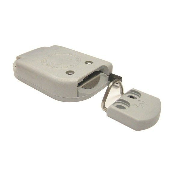
Electronic Lock Components. • Lock Body • Strike (Grey plastic block) Strike loop (Stainless steel wire loop) • Image of Electronic Lock: Image of Strike and Strike loop: Electronic Lock Description. The Electronic Lock body is mounted inside the Locker, while the Door Strike is mounted on the Locker door. Each Electronic Lock is connected to the Locker Controller electronics board(s) by way of a six wire flat ribbon cable. -
Page 4: Lock Wiring
Lock Wiring. • Flat ribbon cable (six way) • Six pole connectors for flat ribbon cable Image of Six pole connector crimped to flat ribbon cable: Locker Door Hinge selection. Select hinges that are of good quality, that will not shift position easily during use. –... -
Page 5: Electronic Lock Positioning
Electronic Lock Positioning. The position of the Metra Electronic Lock, in a locker should be closest to the spot where users are handling the doors; For example: Locker doors with handles; The Electronic Lock should be mounted centrally behind the handle, so that the Door Strike receives the most amount of force to properly close and lock the locker door. -
Page 6: Electronic Lock Wiring Preparation
Electronic Lock wiring preparation. 1. The cable lengths can be calculated by: [Depth of carcass + 100mm (extra cable for lock)] + [Distance to centre of Control cabinet + 500-1000mm] = Total * Note: The cable lengths may need to be increased for the Top and Bottom lockers to account for slightly longer lengths of cable required, as they should be bundled at the centre locker in the Locker carcass. -
Page 7: Preparing To Crimp The Flat Ribbon Cable
2. Mark each end of the cable sequentially, starting at the Top LHS locker, moving down, then across Top RHS etc. The cables should start at # 1 and finish at the last logical Locker number. In the example on the following page (Page 4), i.e. 1 through 32. (RED numbers are the logical Locker numbers, NOT the actual locker numbers) If there were say, 48 lockers in the Locker bank, the cables would be marked 1 through 48, etc. -
Page 8: Crimping The Flat Ribbon Cable
8. The Flat six cable needs to be cut to the desired length. (approx. 100mm excess at the Lock for maintenance purposes and 500-1000mm at the control cabinet) i.e. The cable lengths can be calculated by: Depth of carcass + 100mm (extra cable for lock)] + [Distance to centre of Control cabinet + 500-1000mm] = Total. * Note: The cable lengths may need to be increased for the Top and Bottom lockers to account for slightly longer lengths of cable required, as they should be bundled at the centre locker in the Locker carcass. -
Page 9: Mounting The Electronic Lock Body
12. If crimping either end of the same flat cable, make sure the connectors align as shown below. *Note: The connectors must be aligned in the same direction on the flat cable, otherwise the Electronic Lock will not function. Mounting the Electronic Lock Body. 1) Centralised Locks. - Page 10 • Next, the Lock Body should be mounted first and then the door strike. • There is a single type of Lock Body and it can be used for both Left and Right opening locker doors. • (The lock is simply flipped over, as the mounting holes allow this) •...
- Page 11 – Electronic Lock body is slightly proud of the front face of the Locker carcass. Locking is possible WRONG!! – Electronic Lock body is behind the front face of the Locker carcass. The Locker door strike cannot fully engage into the Electronic Lock body. Locking is NOT possible! Mounting the Electronic Lock Body.
-
Page 13: Metra Rfid Dot Lock
2) RFID DOT Locks. – Lock tip is even with – Lock tip is over the WRONG! – Lock tip is the inner plane of the inner plane of the door. behind the inner plane of door. The door will reach The door will reach the the door and the door the lock tip. - Page 14 NOTE: If the edge of the locker door is not overlapping the inner edge of the locker compartment for at least 6mm, a spacer for the lock is required. As a space, different solutions are possible. The space can also be used to hide the connection cable.
- Page 15 Step 2: Fix the lock in place with 4x screws. NOTE: screws are not supplied by Metra Australia. Step 1: Mounting holes for the door strike should be predrilled in the factory according to the specifications in appendices and according to the requirements described in the chapter. Note: If the lockers are contructed from HPL (or similar) then metal threaded inserts will be required to be pressed into the pre-drilled holes for the screws to engage with.
- Page 16 Step 2: For easier mounting, first stick the plastic cover over the metal pin to the plastic base as shown below. Step 3: First fix the strike with two screws. Use washers between the screw and plastic strike body. Then fix the front cover including the antenna and the protective plastic.
- Page 17 Place the Metra mounting jig on the loop and firmly close the door to position the strike and then tighten the screws. Do not over-tighten the screws, the wire loop should still move freely. Remove the mounting jig. CORRECTLY TIGHTEND SCREWS. Try moving the wire loop left and right in the mount.
- Page 18 Check 1: Press the ejector to check the operation. The motor should operate swiftly. If not, check the wiring or loosen the screws slightly.. Check 2: Close the doors. When closed and locked, the doors should have a fraction (~1mm) of “free movement” under the spring.
-
Page 19: Adjusting The Door Ejector Spring Force On The Electronic Lock Body
Adjusting the Door Ejector spring force on the Electronic Lock body. Depending on the door size and hinge types, the Lock Door ejector spring force may need to be increased or decreased. The Door Ejector is an important part of the Electronic Lock and should be able to push the Locker Door open when unlocked. -
Page 20: Electronic Lock Centralised - Technical Drawing
Electronic Lock – Centralised: Technical drawing. Overhead view of Electronic Lock Body & Strike... -
Page 21: Electronic Lock Rfid Dot - Technical Drawing
Electronic Lock – RFID DOT: Technical drawing. Dimensions... -
Page 22: Cable Entry Hole Drilling Guide For Electronic Lock
Cable entry hole drilling guide for Electronic Lock. - Page 23 Metra Control Cabinet – Preferred back wall layout.
Need help?
Do you have a question about the Metra Electronic Lock and is the answer not in the manual?
Questions and answers