Snorkel A38E Parts And Service Manual
Hide thumbs
Also See for A38E:
- Service manual (136 pages) ,
- Parts & service manual (134 pages) ,
- Operator's manual (30 pages)
Advertisement
Quick Links
Advertisement

Subscribe to Our Youtube Channel
Related Manuals for Snorkel A38E


Summary of Contents for Snorkel A38E
- Page 1 A38E PARTS MANUAL S/N 00715 AND AFTER...
- Page 2 PLATFORM ROTATE CYLINDER ASSEMBLY MOTOR/PUMP ASSEMBLY MANIFOLD BLOCK ASSEMBLY (Hydraulic Platform Rotate) 3-10 ELECTRICAL A38E LOWER CONTROL BOX ASSEMBLY (CE/ASSY) (Harnesses are not part of this assembly) UPPER CONTROL BOX ASSEMBLY ANSI/CE (Hydraulic Platform Rotate) CABLES & ELECTRICAL COMPONENT LEGEND OPTIONS OPTION LIST...
- Page 3 SCHEMATICS Appendix A:Pages Index Appendix B:Parts Index...
- Page 4 PARTS AND SERVICE Part number 514252-201 AUG 2018 Serial Number 01-00715 +...
- Page 5 Proposition 65 Warning Battery posts, terminals and related accessories contain lead and lead components, chemicals known to the State of California to cause cancer and birth defects or other reproductive harm. Wash hands after handling. © Snorkel – all rights reserved...
- Page 6 Underwriters Laboratories Inc. While Snorkel has attempted in every way to confirm that all information in this manual is correct, improvements Additional Information are being constantly made to the machine that may not All correspondence relative to this machine, such as field be reflected in this manual.
- Page 7 Chassis, close to the Steering Cylinder. When contacting Snorkel for service or parts information, sure to include the MODEL and SERIAL NUMBERS from the equipment nameplate. The Serial Number of the Work Platform is also stamped on the inside of the Chassis, close to the Steering Cylinder.
- Page 8 Power Outlet (Optional) Emergency Lowering Lever Guardrails Lower Operator’s Entry Controls Manual Serial Number Chassis Battery Entry Disconnect Step Battery Tie-Down/Lifting Groundstrap Battery Tray Charger Lugs Freewheeling Receptacle Brake Release Right Side Rear Battery Charger Valve LED Charge Indicators A38E – 514252-201...
- Page 9 Description of part the machines that we produce. Quantity of parts required Your purchase order number The specific manuals for A38E aerial platforms are as Address for order to ship to follows: The desired shipment method A38E Operator’s Manual ANSI / CE If ordering parts off-line, the parts order form on the Snorkel part number –...
- Page 10 Parts Order Form Fill out completely and fax attention Parts Department to: Snorkel USA 1-785-989-3077 Snorkel Europe +44 (0) 1952 607 678 Date: Account Number: Company: Purchase Order Number: Address: Model Number: Serial Number: Ship To: Contact Name: Phone Number:...
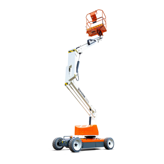
- Page 11 1.1 General Information cylinder features an integral holding valve to prevent uncontrolled descent in the case of a hose burst. The A38E is a quickly deployable self propelled ROTATION GEAR aerial work platform, designed to raise two operators The Booms & Posts Assembly can be rotated to with hand tools to a work height of up to 13.45 m...
- Page 12 DRIVE & STEER SYSTEMS A38E PURPOSE & LIMITATIONS The A38E Work Platform is restricted to low speed The purpose of the A38E work platform is to provide drive when the Platform is raised above the Boom a quickly deployable variable height work platform.
- Page 13 Solid All Surface Tyres With Solid All Surface Tyres Braking Automatic Spring Applied Hydraulic Automatic Spring Applied Hydraulic Release Release Operating temperature range -20oC to +50oC -20oC to +50oC Max Noise Level 69.5 dB(A) 69.5 dB(A) A38E Work Platform Page 5...
- Page 14 Introduction & Specifications Section NOTES: Page 6 A38E Work Platform...
- Page 15 Four lifting straps capable of safely supporting the total weight of the A38E (3,795 Kg ) and at least 250 Refer to Section 2.6 which follows. cm (8 ft.) long are required. This minimum length...
- Page 16 Machine Preparation Section When the A38E is on the Truck it should then be When towing is completed, turn both Allen made secure. head socket screws in a counter clockwise direction until they rest firmly against the locking circlip. Chock the wheels of the A38E.
- Page 17 Fully recharge the batteries, immediately after use. • One charging cycle per day is preferred. • Fully charged batteries perform best. Figure 2.3 – Electrical Compartment • The deeper the discharge, the fewer number of A38E Work Platform Page 9...
- Page 18 Visually check the battery fluid level making sure the level is 3/8″ (10 mm) above the plates. If needed, add distilled water. 10. Tightly replace the caps on each battery Page 10 A38E Work Platform...
- Page 19 A38E PARTS MANUAL S/N 00715 AND AFTER FINAL ASSEMBLY REPAIR PARTS FINAL ASSEMBLY Fri Jul 05 12:03:39 UTC 2019...
- Page 20 A38E PARTS MANUAL S/N 00715 AND AFTER FINAL ASSEMBLY Item Part No. Name 514371-000 Chassis Assembly 515508-000 Booms and Posts Assembly 514554-000 Cage and Cradle Assembly 057580-000 DRIVE GEARBOX 514274-000 DRIVE MOTOR 515652-000 CB2A-F6C1F, BI-DIR PUMP- MOTOR 513429-000 FRONT WHEEL TYRE & RIM...
- Page 21 A38E PARTS MANUAL S/N 00715 AND AFTER CHASSIS ASSEMBLY A38E REPAIR PARTS CHASSIS ASSEMBLY A38E Fri Jul 05 12:03:39 UTC 2019...
- Page 22 A38E PARTS MANUAL S/N 00715 AND AFTER CHASSIS ASSEMBLY A38E Item Part No. Name 514347-000 A38E CHASSIS WELDMENT 500232-000 A38E DRIVE MOTOR COVER 515228-000 A38E CHASSIS BODY COVER ANSI 514348-000 A38E CHASSIS BODY COVER 500231-000 A38E MODULE COVER 500052-000 GRAB HANDLE...
- Page 23 A38E PARTS MANUAL S/N 00715 AND AFTER CHASSIS ASSEMBLY A38E Item Part No. Name 056066-016 Nut, NylockNut DIN985 M16 8.0 057669-000 STEERING STUB AXLE ASSEMBLY (use 4 x 505087-012 Hardened Washer, M12 x 24mm, when securing) 058427-000 A38E TORQUE ARMS...
- Page 24 A38E PARTS MANUAL S/N 00715 AND AFTER CHASSIS ASSEMBLY A38E Item Part No. Name SEE "SIDE TRAY PG SEE "SIDE TRAY PG ASSY" ASSY" 500234-001 A38E CHASSIS SIDE DROP PANEL WITHOUT SLOTS 057580-000 DRIVE GEARBOX 514331-000 CAPACITOR ASSEMBLY 514867-000 CRASH BAR...
- Page 25 A38E PARTS MANUAL S/N 00715 AND AFTER PG PART ASSEMBLY, A38E REPAIR PARTS PG PART ASSEMBLY, A38E Fri Jul 05 12:03:39 UTC 2019...
- Page 26 A38E PARTS MANUAL S/N 00715 AND AFTER PG PART ASSEMBLY, A38E Item Part No. Name 515688-000 GP400c ECU 512943-000 P600 PUMP MOTOR CONTROLLER 502588-000 ALARM, ECCO BEEPING 6- 28VDC 512684-000 ALARM BRACKET 513550-000 CONTACTOR SPDT 200A 12VDC 067387-022 FUSE 512942-000...
- Page 27 A38E PARTS MANUAL S/N 00715 AND AFTER BOOMS & POSTS ASSEMBLY REPAIR PARTS BOOMS & POSTS ASSEMBLY Fri Jul 05 12:03:40 UTC 2019...
- Page 28 A38E PARTS MANUAL S/N 00715 AND AFTER BOOMS & POSTS ASSEMBLY Item Part No. Name 514346-000 A38E 1st POST WELDMENT 515543-001 BALLAST ASSEMBLY CE 058417-000 LOWER LEVEL ROD 058416-000 TURRET WELD 058413-000 LOWER BOOM WELDMENT 514801-000 OUTER BOOM 0260297 WEAR PAD 1-3/4" -4 ACME...
- Page 29 A38E PARTS MANUAL S/N 00715 AND AFTER BOOMS & POSTS ASSEMBLY Item Part No. Name 504505-000 UPPER CYLINDER ASSEMBLY 058734-000 MASTER LEVEL CYLINDER ASSEMBLY 058735-000 SLAVE CYLINDER 058461-000 TELE CYLINDER ASSEMBLY 058056-000 PIN LOCK PLATE 056060-016 BOLT M10 X 16 mm...
- Page 30 A38E PARTS MANUAL S/N 00715 AND AFTER CAGE HYDRAULIC ROTATOR ASSEMBLY REPAIR PARTS CAGE HYDRAULIC ROTATOR ASSEMBLY Fri Jul 05 12:03:41 UTC 2019...
- Page 31 A38E PARTS MANUAL S/N 00715 AND AFTER CAGE HYDRAULIC ROTATOR ASSEMBLY Item Part No. Name 514554-001 A38E BASKET WELDMENT 562386 Literature Compartment 058491-016 Bolt HexSetScrew DIN933 M6 x 1 504120-000 50 DIAMETER FLANGED BUSHING 2 515500-000 BASKET BOTTOM MOUNT 515542-000...
- Page 32 A38E PARTS MANUAL S/N 00715 AND AFTER CAGE HYDRAULIC ROTATOR ASSEMBLY Item Part No. Name 514764-003 PLT, SNORKEL GUARD RH 514764-004 CLAMP PLATE - LH 514764-001 TUBE - ACTUATOR BAR 0260857 514764-008 PLATE SWITCH CLAMP HALF 260838 Hinge Cover, LH...
- Page 33 A38E PARTS MANUAL S/N 00715 AND AFTER WHEEL HUB ASSEMBLY REPAIR PARTS WHEEL HUB ASSEMBLY Fri Jul 05 12:03:41 UTC 2019...
- Page 34 A38E PARTS MANUAL S/N 00715 AND AFTER WHEEL HUB ASSEMBLY Item Part No. Name 057669-000 STEERING STUB AXLE Shown ASSEMBLY (use 4 x 505087-012 Hardened Washer, M12 x 24mm, when securing) 057665-000 WHEEL HUB 057664-000 THRUST BEARING 057662-000 PIVOT BOSS...
- Page 35 A38E PARTS MANUAL S/N 00715 AND AFTER DRIVE REDUCTION GEARBOX ASSEMBLY REPAIR PARTS DRIVE REDUCTION GEARBOX ASSEMBLY Fri Jul 05 12:03:41 UTC 2019...
- Page 36 A38E PARTS MANUAL S/N 00715 AND AFTER DRIVE REDUCTION GEARBOX ASSEMBLY Item Part No. Name COUPLING EXPANSION PLUG STEEL DISC BRONZE DISC O-RING SPACER O-RING ANTI-EXTRUS. RING PISTON SPRING O-RING ANTI-EXTRUS. RING OIL SEAL END PLATE O-RING CIRCLIP BEARING CIRCLIP...
- Page 37 A38E PARTS MANUAL S/N 00715 AND AFTER DRIVE REDUCTION GEARBOX ASSEMBLY Item Part No. Name BEARING RETAINING RING RETAINING RING INPUT FLANGE SCREW SPACER CIRCLIP BEARING COUPLING BEARING SPRING SUN PINION CIRCLIP O-RING THRUST WASHER O-RING RING + BEARING PLANET SHAFT...
- Page 38 A38E PARTS MANUAL S/N 00715 AND AFTER DRIVE REDUCTION GEARBOX ASSEMBLY Item Part No. Name PLUG STUD M15 X 1.5 SCREW CIRCLIP DRIVE REDUCTION GEARBOX ASSEMBLY Fri Jul 05 12:03:41 UTC 2019...
- Page 39 TRACTION MOTOR ASSEMBLY -- SERIAL BREAK: (SN:006001 - 006204 / 006800 - Current) A38E PARTS MANUAL S/N 00715 AND AFTER REPAIR PARTS TRACTION MOTOR ASSEMBLY -- SERIAL BREAK: (SN:006001 - 006204 / 006800 - Current) Fri Jul 05 12:03:41 UTC 2019...
- Page 40 TRACTION MOTOR ASSEMBLY -- SERIAL BREAK: (SN:006001 - 006204 / 006800 - Current) A38E PARTS MANUAL S/N 00715 AND AFTER Item Part No. Name 514274-000 DRIVE MOTOR Shown 514274-001 BRUSH 514274-002 BOLT 514274-003 SPRING 514274-004 BRUSH BOX SUPPORT 514274-005 BRUSH BOX...
- Page 41 A38E PARTS MANUAL S/N 00715 AND AFTER REAR & FRONT WHEEL KIT (NON MARKING) REPAIR PARTS REAR & FRONT WHEEL KIT (NON MARKING) Fri Jul 05 12:03:41 UTC 2019...
- Page 42 A38E PARTS MANUAL S/N 00715 AND AFTER REAR & FRONT WHEEL KIT (NON MARKING) Item Part No. Name 500494-000 REAR & FRONT WHEEL KIT Shown (NON MARKING) SERIAL 004939 TO CURRENT 057578-000 REAR WHEEL NUT - M14 513429-000 FRONT WHEEL TYRE & RIM...
- Page 43 SLEW MOTOR, WORM DRIVE UNIT & SLEW BEARING ASSEMBLY A38E PARTS MANUAL S/N 00715 AND AFTER REPAIR PARTS SLEW MOTOR, WORM DRIVE UNIT & SLEW BEARING ASSEMBLY Fri Jul 05 12:03:41 UTC 2019 2-10...
- Page 44 SLEW MOTOR, WORM DRIVE UNIT & SLEW BEARING ASSEMBLY A38E PARTS MANUAL S/N 00715 AND AFTER Item Part No. Name 500284-001 SLEW MOTOR, WORM DRIVE Shown UNIT & SLEW BEARING ASSEMBLY 500284-000 SLEW DRIVE 500280-000 BOLT 5/8" - 11 UNC X 3 1/2"...
- Page 45 A38E PARTS MANUAL S/N 00715 AND AFTER DECAL KIT ENGLISH (ANSI) REPAIR PARTS DECAL KIT ENGLISH (ANSI) Fri Jul 05 12:03:42 UTC 2019 2-11...
- Page 46 A38E PARTS MANUAL S/N 00715 AND AFTER DECAL KIT ENGLISH (ANSI) Item Part No. Name 500206-001 DECAL KIT ENGLISH Shown 511069-000 DECAL - SNORKEL A38E BOOM 515087-002 OVERLAY 512224-000 DECAL - SNORKEL LOGO 75mm 511067-000 Decal, www.snorkellifts.com 510280-001 DECAL, IPAf EMERG LWR...
- Page 47 A38E PARTS MANUAL S/N 00715 AND AFTER DECAL KIT ENGLISH (ANSI) Item Part No. Name 500438-000 DECAL-AB38 LWR CTRL 057382-000 DECAL-EMER. LOWERING 058537-000 DECAL-PINCH POINT 066555-000 DECAL, RELIEF VALVE 060197-001 DECAL,HYDRAULIC FLUID 514252-000 MANUAL, OPERATORS A38E PG CE/A 068635-001 Harness anchor point...
- Page 48 A38E PARTS MANUAL S/N 00715 AND AFTER DECAL KIT INTERNATIONAL (CE) REPAIR PARTS DECAL KIT INTERNATIONAL (CE) Fri Jul 05 12:03:42 UTC 2019 2-12...
- Page 49 A38E PARTS MANUAL S/N 00715 AND AFTER DECAL KIT INTERNATIONAL (CE) Item Part No. Name 500206-002 DECAL KIT COMPLETE- GERMAN 511069-000 DECAL - SNORKEL A38E BOOM 512940-000 OVERLAY 512224-000 DECAL - SNORKEL LOGO 75mm 511067-000 Decal, www.snorkellifts.com 510280-100 DECAL - EMERGENCY...
- Page 50 A38E PARTS MANUAL S/N 00715 AND AFTER DECAL KIT INTERNATIONAL (CE) Item Part No. Name 060197-001 DECAL,HYDRAULIC FLUID 0070540 DECAL, YELLOW ARROW 0070541 DECAL BLUE ARROW 509722-000 DECAL KIT COMPLETE - FRENCH 511069-000 DECAL - SNORKEL A38E BOOM 512940-000 OVERLAY...
- Page 51 A38E PARTS MANUAL S/N 00715 AND AFTER DECAL KIT INTERNATIONAL (CE) Item Part No. Name 058531-200 DECAL - TIE DOWN/LIFT POINT 068635-001 Harness anchor point 010076-901 DECAL DOCUMENT BOX 060197-001 DECAL,HYDRAULIC FLUID 0070540 DECAL, YELLOW ARROW 0070541 DECAL BLUE ARROW...
- Page 52 A38E PARTS MANUAL S/N 00715 AND AFTER DECAL KIT INTERNATIONAL (CE) Item Part No. Name 510017-000 DECAL - LOWER CONTROL COVER 1 514252-201 SERVICE & PARTS MANUAL 1 058531-200 DECAL - TIE DOWN/LIFT POINT 068635-001 Harness anchor point 010076-901 DECAL DOCUMENT BOX...
- Page 53 A38E PARTS MANUAL S/N 00715 AND AFTER DECAL KIT INTERNATIONAL (CE) Item Part No. Name 512237-000 DECAL - 3 POINT 1 504199-005 DECAL - S.W.L. LARGE 1 058860-000 DECAL - PINCH POINT 2 512233-000 DECAL - LOWER CONTROL COVER 1 514252-201 SERVICE &...
- Page 54 A38E PARTS MANUAL S/N 00715 AND AFTER DECAL KIT INTERNATIONAL (CE) Item Part No. Name 514252-001-NL OPERATORS MANUAL CE 1 7030162-NL DECAL SNORKEL GUARD OVERIDE 1 510221-000 DECAL - 3 POINT 1 504199-005 DECAL - S.W.L. LARGE 1 058860-000 DECAL - PINCH POINT 2...
- Page 55 Local Distributor / Lokaler Vertiebshändler / Distributeur local El Distribuidor local / ll Distributore locale EUROPE, MIDDLE EAST AFRICA & ASIA PHONE: +44 (0) 845 1550 058 FAX: +44 (0) 845 1557 756 NORTH & SOUTH AMERICA PHONE: +1 785 989 3000 TOLL FREE: +1 800 255 0317 FAX: +1 785 989 3070 AUSTRALIA...
- Page 56 Illustrated Parts Breakdown Section HOSE ASSEMBLY 500360-000 A38E Work Platform 7-43...
- Page 57 Illustrated Parts Breakdown Section Non Hydraulic Platform Rotate A38E Work Platform 7-44...
- Page 58 Illustrated Parts Breakdown Section PLATFORM HYDRAULIC ROTATE HOSE/FITTING ASSY (To complete 500360-000) 514349-000 7-45 A38E Work Platform...
- Page 59 Illustrated Parts Breakdown Section Hydraulic Platform Rotate A38E Work Platform 7-46...
- Page 60 A38E PARTS MANUAL S/N 00715 AND AFTER LOWER LIFT CYLINDER HYDRAULICS LOWER LIFT CYLINDER Fri Jul 05 12:03:44 UTC 2019...
- Page 61 A38E PARTS MANUAL S/N 00715 AND AFTER LOWER LIFT CYLINDER Item Part No. Name 515874-000 EXT Ø25 CIRCLIP 515875-000 Ø25 WASHER 515876-000 SPACER 515877-000 M6x1 GREASE NIPPLE 515878-000 M30x3.5 LOCKNUT 515879-000 O-RING 515880-000 Ø85 PISTON RING 515881-000 WEAR RING 80*85*9.7...
- Page 62 A38E PARTS MANUAL S/N 00715 AND AFTER LOWER LIFT CYLINDER Item Part No. Name 515903-000 VALVE BLOCK 515904-000 TRUNNION 515905-000 CYL END (Ø85xØ100x1 515906-000 TUBE(3A08092C-01) LOWER LIFT CYLINDER Fri Jul 05 12:03:44 UTC 2019...
- Page 63 A38E PARTS MANUAL S/N 00715 AND AFTER UPPER LIFT CYLINDER ASSEMBLY HYDRAULICS UPPER LIFT CYLINDER ASSEMBLY Fri Jul 05 12:03:44 UTC 2019...
- Page 64 A38E PARTS MANUAL S/N 00715 AND AFTER UPPER LIFT CYLINDER ASSEMBLY Item Part No. Name 504505-000 UPPER CYLINDER ASSEMBLY Shown CYLINDER BODY 500397-000 EMERGENCY LOWERING VALUE 058728-000 SINGLE OVERCENTRE VALVE END CAP ROD AND END PIVOT 500458-000 SEAL KIT KIT ITEM...
- Page 65 A38E PARTS MANUAL S/N 00715 AND AFTER TELESCOPIC CYLINDER ASSEMBLY HYDRAULICS TELESCOPIC CYLINDER ASSEMBLY Fri Jul 05 12:03:44 UTC 2019...
- Page 66 A38E PARTS MANUAL S/N 00715 AND AFTER TELESCOPIC CYLINDER ASSEMBLY Item Part No. Name 058461-000 TELE CYLINDER ASSEMBLY Shown CYLINDER BODY 058728-000 SINGLE OVERCENTRE VALVE 058714-000 SINGLE P.O. CHECK VALVE END CAP ROD AND END PIVOT 500459-000 SEAL KIT (6 THRU 9,...
- Page 67 A38E PARTS MANUAL S/N 00715 AND AFTER STEERING CYLINDER ASSEMBLY HYDRAULICS STEERING CYLINDER ASSEMBLY Fri Jul 05 12:03:45 UTC 2019...
- Page 68 A38E PARTS MANUAL S/N 00715 AND AFTER STEERING CYLINDER ASSEMBLY Item Part No. Name 058463-000 STEERING CYLINDER Shown ASSEMBLY CYLINDER BODY CYLINDER ROD 500460-000 SEAL KIT (CONTAINS 3, 5, 6 AND 7) KIT ITEM WEARBAND END CAP KIT ITEM O-RING...
- Page 69 A38E PARTS MANUAL S/N 00715 AND AFTER MASTER/SLAVE CYLINDER ASSEMBLY HYDRAULICS MASTER/SLAVE CYLINDER ASSEMBLY Fri Jul 05 12:03:45 UTC 2019...
- Page 70 A38E PARTS MANUAL S/N 00715 AND AFTER MASTER/SLAVE CYLINDER ASSEMBLY Item Part No. Name 058734-000 MASTER LEVEL CYLINDER Shown ASSEMBLY 058735-000 SLAVE CYLINDER Shown CYLINDER BODY VALVE BLOCK BODY 058728-000 SINGLE OVERCENTRE VALVE END CAP ROD AND END PIVOT 058750-000...
- Page 71 A38E PARTS MANUAL S/N 00715 AND AFTER PLATFORM ROTATE CYLINDER ASSEMBLY HYDRAULICS PLATFORM ROTATE CYLINDER ASSEMBLY Fri Jul 05 12:03:45 UTC 2019...
- Page 72 A38E PARTS MANUAL S/N 00715 AND AFTER PLATFORM ROTATE CYLINDER ASSEMBLY Item Part No. Name CYLINDER 12330 PLATFORM ROTATE CYLINDER Shown ASSEMBLY 12330 Cylinder, Rotator 1 12330K SEAL KIT 514352-000 ADAPTER, 6ORB - 1/4” BSP MALE-MALE STRAIGHT 514352-000 ADAPTER, 6ORB - 1/4” BSP...
- Page 73 A38E PARTS MANUAL S/N 00715 AND AFTER MOTOR/PUMP ASSEMBLY HYDRAULICS MOTOR/PUMP ASSEMBLY Fri Jul 05 12:03:45 UTC 2019...
- Page 74 A38E PARTS MANUAL S/N 00715 AND AFTER MOTOR/PUMP ASSEMBLY Item Part No. Name 515652-000 CB2A-F6C1F, BI-DIR PUMP- MOTOR 515921-000 Motor 48VDC 4KW 1750RPM S2=15Min 515652-100 Pump CB2A-F6C1F 6.37cc/r, 20Mpa 1 515923-000 Screw M10X25 515924-000 Spring Washer Ø10 515925-000 Flat washer Ø10...
- Page 75 A38E PARTS MANUAL S/N 00715 AND AFTER MANIFOLD BLOCK ASSEMBLY (Hydraulic Platform Rotate) HYDRAULICS MANIFOLD BLOCK ASSEMBLY (Hydraulic Platform Rotate) Fri Jul 05 12:03:45 UTC 2019 3-10...
- Page 76 A38E PARTS MANUAL S/N 00715 AND AFTER MANIFOLD BLOCK ASSEMBLY (Hydraulic Platform Rotate) Item Part No. Name 514351-000 A38E MANIFOLD BLOCK Shown (Hydraulic Platform Rotate) MAIN MANIFOLD BLOCK ONLY 6010472 VALVE CARTRIDGE 514526-000 COIL 12567-4 Cartridge, Solenoid - Spool, 4-Way,...
- Page 77 A38E LOWER CONTROL BOX ASSEMBLY (CE/ASSY) (Harnesses are not part of this assembly) A38E PARTS MANUAL S/N 00715 AND AFTER ELECTRICAL A38E LOWER CONTROL BOX ASSEMBLY (CE/ASSY) (Harnesses are not part of this assembly) Fri Jul 05 12:03:46 UTC 2019...
- Page 78 A38E LOWER CONTROL BOX ASSEMBLY (CE/ASSY) (Harnesses are not part of this assembly) A38E PARTS MANUAL S/N 00715 AND AFTER Item Part No. Name 515045-000 A36E LCB ENCLOSURE 3028810 PUSH/PULL SW ASSY W/CONTACT 512543-000 3 POS'N KEY SWITCH - STAYPUT...
- Page 79 UPPER CONTROL BOX ASSEMBLY ANSI/CE (Hydraulic Platform Rotate) A38E PARTS MANUAL S/N 00715 AND AFTER ELECTRICAL UPPER CONTROL BOX ASSEMBLY ANSI/CE (Hydraulic Platform Rotate) Fri Jul 05 12:03:46 UTC 2019...
- Page 80 UPPER CONTROL BOX ASSEMBLY ANSI/CE (Hydraulic Platform Rotate) A38E PARTS MANUAL S/N 00715 AND AFTER Item Part No. Name 515040-000 A38E UCB ENCLOSURE 514404-001 FLASHING BEACON BLUE 515049-000 GP200 ECU 21 200 301 3049862 Receptacle Flgd HD30, 14 Way 514604-000...
- Page 81 UPPER CONTROL BOX ASSEMBLY ANSI/CE (Hydraulic Platform Rotate) A38E PARTS MANUAL S/N 00715 AND AFTER Item Part No. Name 510156-000 9WAY PANEL PLUG 510154-000 6WAY PANEL PLUG 509755-000 Mate-N-lock socket contact UPPER CONTROL BOX ASSEMBLY ANSI/CE (Hydraulic Platform Rotate) Fri Jul 05 12:03:46 UTC 2019...
- Page 82 A38E PARTS MANUAL S/N 00715 AND AFTER CABLES & ELECTRICAL COMPONENT LEGEND ELECTRICAL CABLES & ELECTRICAL COMPONENT LEGEND Fri Jul 05 12:03:47 UTC 2019...
- Page 83 A38E PARTS MANUAL S/N 00715 AND AFTER CABLES & ELECTRICAL COMPONENT LEGEND Item Part No. Name 515521-000 A38E WIRE HARNESS TO PLATFORM AND GROUND CONTROL PANELS KIT 515521-001 PANELS KIT ,PLATFORM CABLE HARNESS 515521-002 PANELS KIT ,GROUND PANEL CABLES 513540-001...
- Page 84 A38E PARTS MANUAL S/N 00715 AND AFTER OPTION LIST OPTIONS OPTION LIST Fri Jul 05 12:03:47 UTC 2019...
- Page 85 A38E PARTS MANUAL S/N 00715 AND AFTER OPTION SNORKEL GUARD OPTIONS OPTION SNORKEL GUARD Fri Jul 05 12:03:48 UTC 2019...
- Page 86 A38E PARTS MANUAL S/N 00715 AND AFTER OPTION SNORKEL GUARD Item Part No. Name 514675-001 Basket Weldment 514557-000 Pla orm Step Weldment 514677-000 Actuator Bar Weldment 514684-000 Clamp Mount Weldment LH 514685-000 Clamp Mount Weldment RH 514686-000 Switch Clamp Weldment...
- Page 87 A38E PARTS MANUAL S/N 00715 AND AFTER ADDITIONAL OPTIONS, A38E OPTIONS ADDITIONAL OPTIONS, A38E Fri Jul 05 12:03:48 UTC 2019...
- Page 88 Snorkel recommends that you make additional copies of If a part resists removal, check to see if all fasten- the preventative inspection and maintenance checklists ers, electrical wiring, hydraulic lines, etc., have...
- Page 89 Shields, covers, seals and filters help to keep air and oil supplies clean. However, these items must be maintained Replace any guards and protective devices that have been on a scheduled basis in order to function properly. removed to carry out maintenance and repair work. Maintenance – 2 A38E...
- Page 90 Operating controls – Proper operation Boom functions, drive, brakes, etc. Emergency stop and emergency power Shuts off upper controls/proper operation Horn Sounds when activated Snorkel Guard Proper operation Placards and Decals In place and readable Performed by: Date: A38E Maintenance – 3...
- Page 91 Maintenance – 4 A38E...
- Page 92 Upper / Lower Cylinders Check Cylinder rod for wear Check pivot pin retaining rings Grease all fittings Entire unit Lubricate Grease all fittings Turntable (Slew) Grease Slew gear Clear and lubricate,check for damage Interflon LS 1/2 Performed by: Date: A38E Maintenance – 5...
- Page 93 Rotation backlash Check for wear and damage Operator’s Manual Proper manual in document holder System pressure Check maximum system pressure 175 Bar (2538 p.s.i.) Decals and placards Check for damage and readability Order replacements as necessary Maintenance – 6 A38E...
- Page 94 Slave level cylinder holding valves Check for leaks, wear, damage, and for proper operation Rotate cylinder and holding Check for leaks, wear, damage, and valves for proper operation Decals and placards Check for damage and readability Order replacements as necessary A38E Maintenance – 7...
- Page 95 Hydraulic system cold weather warm Check for proper operation up kit Driving lights Check for proper operation Platform work lights Check for proper operation Platform control cover Check condition and for proper operation Airline to platform Check for proper operation Maintenance – 8 A38E...
- Page 96 EP.2 Lithium Grease Platform rotator Refill if disassembled for repairs Consult factory Platform controller Check smooth operation/speeds Batteries Check specific gravity 1.28(US 1275)at 32.2° C(90°F) Hydraulic return filter Check condition Replace if dirty Performed by: Date: A38E Maintenance – 9...
- Page 97 Gear hubs Replace fluid Overload Calibrate System Drive motors Check for wear of brushes Check that commutator or springs are undamaged. Change oil in drive reduction CWD2012/CFD/42,4A.D.IEC gearbox (7,06x6_OMALA150) Omala or Shell Oil Performed by: Date: Maintenance – 10 A38E...
- Page 98 Major Repairs Date Part Number Part Description Repair Performed A38E Maintenance – 11...
- Page 99 Grease Fitting Lubrication 1. Rotate the Gearbox into the horizontal position with Specific lubricants as recommended by Snorkel, should one of the filler/drain plug holes in the 3 O’ Clock- be used in maintaining the unit. If in doubt regarding position and the other plug hole above it.
- Page 100 1. New batteries need to be cycled several times before If questions still remain, contact Snorkel Customer Ser- reaching full capacity (20-50 cycles, depending on vice Department for further information. type). Usage should be limited during this period.
- Page 101 Cold reduces bat- tery capacity and retards charging. Heat increases water usage and can result in overcharging. Very high temperature can cause “thermal run away” which may lead to an explosion or fire. If extreme Maintenance – 14 A38E...
- Page 102 A38E Maintenance – 15...
- Page 103 The chart may be used with both coarse and fine thread fasteners lightly lubricated. Increase torque by 20% when multiple tapered tooth (shake proof) lock washers are used. The torque values are given in foot-pounds. Inch/pound equivalent may be obtained by multiplying by 12. Maintenance – 16 A38E...
- Page 104 Foot/pound equivalent may be obtained by dividing by 12. Inch/pound equivalent may be obtained by multiplying by 12. Newton/meter equivalent may be obtained by multiplying inch/pound by 0.1130. Newton/meter equivalent may be obtained by multiplying foot/pound by 1.3558. A38E Maintenance – 17...
- Page 105 W A R N I N G understanding the operation and function of the Before performing preventative maintenance various components and systems of the A38E Work familiarise yourself with the operation of the Platform and help in diagnosing and repair of the machine.
- Page 106 Section Notes:...
- Page 107 Rinse thoroughly with clean, warm water. Clean battery and cable contact surfaces to a bright metal finish whenever a cable is removed. A38E Work Platform...
- Page 108 Maintenance Process Section 4.3 Temperature correction for All Snorkel battery operated Work Platforms, including the A38E can operate at ambient Electrolyte readings temperatures to a value of -20ºC (-4ºF). However for this there are two provisions which must be met.
- Page 109 DO NOT fill above the upper line on the dipstick or Upper Boom when the platform is elevated. Telescopic Boom Note: oil grades may vary depending on machine Lower Cylinder (including Trunnions) specification. Contact Snorkel Product Support for Upper Cylinder further advice. Telescopic Cylinder Oil and Filter Replacement Master Cylinder...
- Page 110 Manifold with Hydraulic Platform Rotate Slew Cross Main Relief Line Relief Valve Valve (RVI) (CR1) Manifold with Manual/No Platform Rotate Pressure Test Point Slew Cross Line Relief Main Relief Valve Valve Figure 4-4: Setting Main Relief Pressures Figure 4-3: Manifold Block A38E Work Platform...
- Page 111 1. Select Lower Control Boom 1 Switch and gradually raise the platform until the sling can be removed. 2. Remove the sling. 3. Completely lower platform. 4. Turn Key Switch to “OFF” Figure 4-6: Supporting Elevating Assy. A38E Work Platform...
- Page 112 Rest is located on the side of the First Post on the The Tilt Sensor is incorporated in the GP400 control module. A38E Work Platform. The high speed drive can only be operated when this switch is activated. When the Function: This limit switch is activated when the boom leaves the boom rest the Normally Open con- internal sensor in the ‘Tilt Sensor’...
- Page 113 Maintenance Process Section Elevating Assembly Lower Boom Upper Boom Switch Body Switch Head Figure 4-8: Boom Rest Limit Switch A38E Work Platform...
- Page 114 Inspect the manifold for cracks, thread damage and scoring where O-rings seal against internal and external surfaces. Wash and dry each component and check for thread damage, torn or cracked O-rings and proper operation. Replace parts and O-rings found unserviceable. 4-10 A38E Work Platform...
- Page 115 (for Hydraulic Platform Rotate manifold for see page 4-6) Main Relief Valve Pressure Test Point Telescopic Retraction Valve (Only one valve on Hydraulic Platform Rotate manifold) Cross Line Relief Valves Refer to page 7-31/7-33 for partnumbers Figure 4-9: Manifold Block Components A38E Work Platform 4-11...
- Page 116 Push the springs back in place. Check the constant pressure on all the brushes, and the correct contact with the commutator. Replace the inspection/ventilation covers. Pressure Hose Suction Hose Capscrew Pump Assembly Electric Motor Non return valve Figure 4-10: Hydraulic Pump 4-12 A38E Work Platform...
- Page 117 If necessary replace with bearings using the following procedure: of identical type. a. Place paper strip between brush face and Screws - Check that all nuts, particularly the commutators. See Figure 8. cable nuts and screws are tight. A38E Work Platform 4-13...
- Page 118 Install new brushes and be sure they are free in Supply the holder. Install brush with the lead wires VOLTMETER positioned as when received. Place commutator cover on a work bench with brush assembly facing upward. Figure 4-12: Electrical Test Circuit 4-14 A38E Work Platform...
- Page 119 To solve this disassemble and reconnect in the proper way. Reversing the polarity will not solve this problem as this is a series wound motor. A38E Work Platform 4-15...
- Page 120 4.11 Pump Bearing Pulley End Cover Pulley End Bearing Armature Commutator Bearing Stator Housing Brush Housing Support Commutator End Cover Inspection Cover Brush Holders Brush Retaining Spring Brushes Retaining Bolt Coupling Figure 4-13: Electric Motor Assembly 4-16 A38E Work Platform...
- Page 121 Maintenance Process Section 4.12 4.12 Drive Reduction Gearbox During oil change, we recommend that the inside of the Gearcase is flushed out with flushing fluid (Figure 4-14) recommended by the lubricant manufacturer. Oil should be changed when hot to prevent a build up of sludge deposit.
- Page 122 Loosen the five wheel nuts securing the Wheel Assembly to the Gearbox studs. 4.13 Torque Specifications Jack up the rear of the A38E and chock the front wheels to prevent the machine from moving during the service. RETAINING BOLTS Remove the Wheel Assembly by unscrewing...
- Page 123 The Lower Lift Cylinder is heavy, so utilise appropriate lifting equipment to support the unit before removing pins. Ensure that the A38E is on firm level ground, the Elevating Assembly is completely stowed, the Keyswitch is to the ‘OFF’ position and the Emergency Stop Button is pressed.
- Page 124 Breakdown. Cylinder Body Piston O-Ring Grease Nipple Piston Head Overcentre Cartridge Piston Seal End Cap Piston Locknut Rod And Pivot Washer Rod Seal Emergency Lowering O-Ring Valve Wiper Spacer Figure 4-16: Hydraulic Cylinder Component Breakdown 4-20 A38E Work Platform...
- Page 125 The Upper Lift Cylinder is heavy, so utilise appropriate lifting equipment to support the unit before removing pins. Ensure that the A38E is on firm level ground, the Elevating Assembly is completely stowed, the Keyswitch is to the ‘OFF’ position and the Emergency Stop Button is pressed.
- Page 126 Thread headcap onto barrel tube and hand tighten, then turn 1/4 turn further. REMOVAL Install the upper cylinder Overcentre valve. Ensure that the A38E is on firm level ground, INSTALLATION the Elevating Assembly is completely stowed, the Keyswitch is to the ‘OFF’ position and the NOTE: Before installing Lift Cylinder check cylinder Emergency Stop Button is pressed.
- Page 127 REMOVAL Replace any parts or seals found to be unserviceable. Ensure that the A38E is on firm level ground, REASSEMBLY/SEAL REPLACEMENT the Elevating Assembly is completely stowed but slewed away from centre, the Keyswitch is Note: During seal replacement do not use sharp to the ‘OFF’...
- Page 128 Polishing is washers and bolts at the front panel of the a sign of uneven loading and if sufficiently A38E’s chassis. polished the affected parts should be replaced. Move the steering arm so that the holes for Replace any parts or seals found to be positioning the pins are correct.
- Page 129 Replace any parts or seals found to be Ensure that the A38E is on firm level ground, unserviceable. the Elevating Assembly is completely stowed, the Keyswitch is to the ‘OFF’ position and the REASSEMBLY/SEAL REPLACEMENT Emergency Stop Button is pressed.
- Page 130 Unscrew the piston nut and remove piston and headcap from the cylinder rod. Remove the piston static O-ring from the Ensure that the A38E is on firm level ground, cylinder rod. the Elevating Assembly is completely stowed, Remove the piston seal from the piston.
- Page 131 Maintenance Process Section 4.19 INSTALLATION Switch while a colleague holds a cloth at the fitting ‘B’. Air will be expelled through this fitting. Activate the Switch slowly in both directions NOTE: Before installing the Slave Cylinder check until all air is expelled and hydraulic fluid begins cylinder pins and bearings for wear and replace if to appear.
- Page 132 Maintenance Process Section 4.20 4.20 Adjustment of Overcentre Valves on A38E Lift Cylinders (Figure 4-22) The valve supplier delivers the Overcentre valve preset to specification and SHOULD NOT be adjusted by the user. In the event of the valve having been tampered with the advisable course of action is to fit a replacement cartridge.
- Page 133 Maintenance Process Section Section 4.21 4.21 4.21 REPLACEING THE GP400 Now Re-Calibrate the loadcell:- CONTROL MODULE Scroll to setups. (Enter) Scoll to load setups. (Enter) If for any reason you have to replace the GP400 control Scoll to Calibrate load (Enter) moduale it is important that you complete the following Redo loaded? Press up arrow for yes, place SWL procedures:...
- Page 134 Maintenance Process Section 4.22 4.22 CALLIBRATION OF THE LOAD CELL If for any reason you have to replace the LOAD CELL it is important that you complete the following procedures: W A R N I N G If the LOAD CELL is replaced and /or tampered with for any reason the loadcell must be re-calibrated using the following procedure.
- Page 135 Section 6.0 will aid in understanding the operation and function of the verious components 4. Repair or replace any component found to be and systems of the A38E Work Platform and help faulty. diagnosing and repair of the machine.
- Page 136 • Crimping Tool (Snorkel P/N: 028800-009) Switch the machine on, press and hold Esc for 5 seconds until “SNORKEL EBOOM” is displayed • Terminal Removal Tool ( Snorkel P/N: 028800-006) than select diagnostics, the following menu’s are available: • Calibrator EZcal ( Snorkel P/N: 504560-001)
- Page 137 W A R N I N G RISK OF SERIOUS INJURY. Ensure that the work platform is resting on firm, level surface. The elevating assembly must be supported by an overhead hoist when troubleshooting and servicing the electrical/hydraulic system. A38E Work Platform...
- Page 138 Oil flow indicates a faulty cylinder piston seal. Remove and repair the cylinder. 3. Platform is overloaded Remove excessive weight. The Safe Working Load is 215 kg for A38 A38E Work Platform...
- Page 139 Blocked brake line to either motor. Clear blockage and/or replace malfunction hoses and fittings. Check the correct function of the check valves V1 and V2 on the valve block. These valve should open to allow brake chamber evacuation. A38E Work Platform...
- Page 140 Troubleshooting Section NOTES: A38E Work Platform...
- Page 141 Redo empty? Press up arrow for yes, remove load from platform and press enter twice. Use arrow to enter calabration date and press Enter. Place 120% of SWL in the platform and verify that the lift function cuts out automatically when raised off the boom switch. A38E Work Platform...
- Page 142 Std 0.5V/2.5V/4.5V gnd finger joystick P8-13 P8-15 Basket Rotate P15-1 B+ Digital Input Ground control; enable function, direction and proportional control Basket Level P15-2 B+ Digital Input from gnd fingerjoystick (P8-1), need to hold while function A38E Work Platform...
- Page 143 Schematics Section 6.0 Introduction This section contains electrical and hydraulic power schematics and associated information for maintenance purposes. A38E Work Platform...
- Page 144 Schematics Section A38E CE/ANSI Electric Kit Parts. DESCRIPTION PART NUMBER QTY. External Components PLATFORM CONTROL BOX 515039-000 12v Solenoid coil 505555-016 A38E UCB ENCLOSURE 15040-000 Alarm 502588-000 BEACON BLUE FLASHING 514404-001 Alarm bracket 512684-000 GP200 ECU 21 200 301 515049-000...
- Page 145 Schematics Section Electrical Schematics A38E Work Platform...
- Page 146 Schematics Section A38E CE/ANSI Electric Options: Horn Sound on E/Stop, Emergency Power Desend, Drive Light. Circuit Diagram: 515490-000 OPTIONS DESCRIPTION PART NUMBER QTY (PER M/C) HORN SOUND ON E/STOP N/O CONTACT BLOCK 510527-000 EMERGENCY POWER DESCEND POWER UNIT 6020058 BATTERY...
- Page 147 Schematics Section 6.2. Hydraulic Schematics Table 6-3: Hydraulic Schematic Legend REFERENCE NAME FUNCTION LOCATION REFERENCE NAME FUNCTION LOCATION BRAKE Brake. Spring applied - hydraulically On front end of Steer Send oil to the annular or full- On main released brakes to stop wheel drive Directional bore side of the steering...
- Page 148 A38E PARTS MANUAL S/N 00715 AND AFTER Appendix A:Pages Index REAR & FRONT WHEEL KIT (NON MARKING) 2-9 A38E LOWER CONTROL BOX ASSEMBLY SCHEMATICS (CE/ASSY) (Harnesses are not part of this SLEW MOTOR, WORM DRIVE UNIT & SLEW assembly) BEARING ASSEMBLY...
- Page 149 A38E PARTS MANUAL S/N 00715 AND AFTER Appendix B:Parts Index 057429-000 2-11 0070540 2-11, 2-12, 2-12, 2-12, 2-12, 2-12 057430-002 2-11, 2-12, 2-12, 2-12, 2-12, 2-12 0070541 2-11, 2-12, 2-12, 2-12, 2-12, 2-12 057434-001 2-11 0070921 2-11 057507-024 2-12 010076-001...
- Page 150 A38E PARTS MANUAL S/N 00715 AND AFTER 058181-002 2-12 067387-022 058181-003 2-11 068635-001 2-11, 2-12, 2-12, 2-12, 2-12, 2-12 058413-000 100338-013 4-1, 4-2 058416-000 11492-1 2-5, 2-5 058417-000 12-3149 3-10 058427-000 12330 2-1, 2-5, 3-8 058457-002 12330K 058461-000 2-1, 2-4, 3-5...
- Page 151 A38E PARTS MANUAL S/N 00715 AND AFTER 500234-001 500519-006 500234-002 501074-000 500234-003 501085-000 500250-000 501868-001 500252-000 501964-000 500253-001 501964-001 500254-000 502588-000 2-3, 4-2 500259-000 503101-040 500260-000 504120-000 500261-000 504199-005 2-12, 2-12, 2-12, 2-12, 2-12 500261-002 3-10 504504-001 500261-004 3-10 504504-002...
- Page 152 A38E PARTS MANUAL S/N 00715 AND AFTER 510221-000 2-12 513542-005 510280-001 2-11 513542-006 510280-100 2-12, 2-12, 2-12, 2-12, 2-12 513542-008 510521-000 513542-009 510542-000 513542-010 510561-008 513542-011 510566-055 513542-012 510848-000 2-12 513542-013 511027-003 2-12, 2-12, 2-12, 2-12, 2-12 513542-014 511028-001 2-11...
- Page 153 A38E PARTS MANUAL S/N 00715 AND AFTER 514274-008 514686-000 514274-009 514688-000 514274-010 514689-000 514274-011 514698-000 2-11 514274-012 514698-000 * 514331-000 514698-000-DE 2-12 514346-000 514698-000-ES 2-12 514347-000 514698-000-FR 2-12 514348-000 514698-000-IT 2-12 514349-000 514698-000-NL 2-12 514351-000 2-2, 3-10 514764-000 514352-000 3-8, 3-8...
- Page 154 A38E PARTS MANUAL S/N 00715 AND AFTER 515502-002 515887-000 515502-003 515888-000 515505-000 515889-000 515508-000 515890-000 515521-000 515891-000 515521-001 515892-000 515521-002 515893-000 515541-000 515894-000 515542-000 515895-000 515543-001 515896-000 515591-000 2-11 515897-000 515606-000 515898-000 515607-000 515899-000 515611-000 515900-000 515622-000 515901-000 515652-000 2-1, 2-2, 3-9...
- Page 155 A38E PARTS MANUAL S/N 00715 AND AFTER 7030161-NL 2-12 7030162 2-11 7030162 * 7030162-DE 2-12 7030162-ES 2-12 7030162-FR 2-12 7030162-IT 2-12 7030162-NL 2-12 8628 CYLINDER 12330 SEE "SIDE TRAY PG ASSY" Fri Jul 05 12:03:51 UTC 2019...
Need help?
Do you have a question about the A38E and is the answer not in the manual?
Questions and answers