
Related Manuals for Airflow MultiPlexBox


Summary of Contents for Airflow MultiPlexBox
- Page 1 80001028 – Issue 1 11/20 MultiPlexBox Part No: 90001255/90001256/90001257/90001258 General Manual on the correct usage, maintenance, and installation of the MultiPlexBox Unit...
-
Page 2: Table Of Contents
0 . C o n t e n t s Contents 0. Contents ................................... 2 1.0 General Information ................................ 3 1.1 Important technical information ..........................3 1.2 Warranty and liability claims ............................. 3 1.3 Regulations – Guidelines ............................3 1.4 Intended use ................................3 1.5 Scope of delivery .............................. -
Page 3: General Information
> 10 μm in air and liquid is not permitted. Transport media, which affect the fan materials, and abrasive media are not permitted. 1.5 Scope of delivery The delivery consists of one box containing the MultiPlexBox unit and the installation and operating instructions 1.6 Shipping The unit is packed ex works in such a way that it is protected against normal transport strain. -
Page 4: Storage / Warehousing
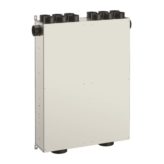
1.9 Functional description The MultiPlexBox is used for the individual ventilation control of connected zones for example: (apartment, office, commercial unit) in combination with a central ventilation system. The unit consists of a supply air chamber and an extract air chamber (see figure 1). -
Page 5: Technical Data
Monitoring systems are always integrated in the unit supply line (see wiring diagram). 1.11 Technical data Please refer to the tables below for detailed technical information on the MultiPlexBox units: 125mm X 75mm MultiPlexBox Left and Right-handed. – 90001255, 90001256 Installation room requirements: 5-55°C <95 %... - Page 6 Dimensions MultiPlexBox Right 90° 125 mm x 75 mm – 90001255 MultiPlexBox Left 90° 125 mm x 75 mm – 90001256 MultiPlexBox straight through 75mm - 90001257 MultiPlexBox straight through 125mm – 90001258...
-
Page 7: Accessories
Shorten the duct parallel to the rings. To avoid leaks, the pipe must not be cut at an angle. The MultiPlexBox is prepared for the connection of 125 mm pipes on the inlet side. The supply air and extract air ducts in the rooms are designed with 75mm Airflex Pro round pipe. - Page 8 2.3 Mounting The unit can be vertically or horizontally mounted to the wall, a sloping roof, or the ceiling using the drilling attachment points indicated with arrows on figure 6. (see Fig. 6, 7,8, 9). The connection plate – 90001252 Is available for suspended and concrete installation.
- Page 9 The ventilation pipe and duct connections must be designed in such a way that there is no force effect on the MultiPlexBox connectors. 5. Lead the ducts to the unit spigots for each corresponding room. If necessary, shorten the AirflexPro pipe and insert up to the correct stop in the corresponding spigot.
- Page 10 2.5.2 Installation of the connection plate. The connection plate (90001252) which is available as an accessory, is intended for suspended setting in a concrete ceiling. As well as this, suspended installation in a lightweight wall or ceiling is possible. 1. Place the adapter plate in the desired position on the formwork with the rubber seal, as specified in the construction plan.
- Page 11 Ensure the correct assignment of supply air and extract air, as this can no longer be changed! 2. Finished and correct concreting of the connection plate including Airflex Pro 2.5.4 Connecting the MultiPlexBox with the connection plate. C. Wide mounting B.
- Page 12 1. Remove the dust protection caps on the required connectors. Ensure that small parts do not fall into the MultiPlexBox, as this can result in faults or noise generation during operation. 2. Then insert the right number of plastic fittings from the connection set and lock into the connectors.
- Page 13 2.5.1 Electrical connection points Refer to table below for reference to connection points on the MultiPlexBox control panel. A. Mains Voltage (230 V AC) B. Switching contact (potential-free max. 5 A) C.
- Page 14 MultiPlexBox connections K - Exhaust air damper motor - Pressure Sensor supply air L H - Pressure Sensor supply air H L - Supply air damper motor I - Pressure Sensor extract air L M - Sensor J - Pressure Sensor extract air H N - Fine fuse T 3.15 A...
- Page 15 (see following figure). ECO Controller connections Please refer to the wiring diagram 1 for more instructions on wiring the ECO controller to the MultiPlexBox. Please refer to the wiring diagram 1 for instruction on making the electrical connection.
- Page 16 Touchscreen Controller connections Please refer to the wiring diagram 2 for more instructions on wiring the controller to the MultiPlexBox. Please refer to the wiring diagram 2 RS484 A RS484 B + 12 V Diagram 2: Touchscreen Controller...
- Page 17 The MultiPlexBox allows up to three digital inputs with an "external" switch or button. Every digital input can (de)activate another function. These can be defined in the commissioning software. Please refer to the wiring diagram below: 2.8 Assembling the Central Controller...
- Page 18 WARNING Failure to comply with regulations and warnings may result in serious injury or fatal accidents with which Airflow Developments cannot be held responsible for. • Assembly and maintenance work may only be carried out by a recognised person.
- Page 19 2.8.4 Required and optional accessories Power connection: Installation cable 3x1.5 or 3x1 Control panel: Signal cable J-Y(St)Y 2x2x0.6 (length max. 100 m) Modbus: Standard network accessories CAT.5 or CAT.7 with RJ45 connectors (cable length max. 600 m, from the first to the last device) LAN: Standard network accessories CAT.5 or CAT.7 with RJ45 connectors USB: Standard USB cables (max.
- Page 20 MultiPlexBox Address List In the appendix ("Annex - MultiPlexBox Address List") you will find a table in which you can document the device location and device addresses of the boxes during assembly. You can detach or copy the list or print it from a PDF (download).
- Page 21 Series Connection: Central Controller (Master) MultiPlexBox (Slave) Ω Resistor...
- Page 22 Double series connection: Central Controller (Master) MultiPlexBox (Slave) Ω Resistor...
-
Page 23: Software
2.9 MultiPlexBox Address List In the appendix (MultiPlexBox Address list) you will find a table in which you can document the device location and device addresses of the flat boxes during assembly. You can detach or copy the list or print it from a PDF (download). - Page 24 3.1.2 Configuration Menu This will allow you to configure the MultiPlexBox. In this menu you will find the options for naming the unit, setting its location, its unit address, what controller it uses and its desired function switching contact.
- Page 25 Adjust volume flow for supply and extract air levels 1-3, basic This allows you the option to make an air volume flow adjustment within the different ventilation levels. You can input an increase or decrease in airflow from the setpoint airflows to the actual unit airflow from this menu. •...
- Page 26 1500 1000 Table 1: Sensor Values • Service level This is only intended for operation by the Airflow Developments service team. 3.2.3 Saved Settings • Load from file Allows you to load your saved configuration from your windows file explorer.
- Page 27 1st Menu Submenu Ventilation Ventilation Level Set Supply air volume Set Extract air volume Supply Air Volume Extract Air Volume Damper Position Supply Damper Position Extract Sensor Humidity (RH) Air Quality (VOC) Firmware Version Main Version Side Version Errors Current Error Error History Menu: Configuration Submenu...
-
Page 28: Commissioning
A contaminated duct network can lead to ventilation component malfunctions! • The MultiPlexBox is connected to the mains power supply. The MultiPlexBox requires an external power supply. •... - Page 29 Controller and helps to save time. • Install the software for later. Airflow Developments recommends installing and updating the MultiPlexBox software before arriving on site as you may not have the internet access to do so which will leave you unable to commission the unit.
- Page 30 Airflow Developments Limited Email: info@airflow.com Aidelle House, Lancaster House Telephone: +44(0)1494 525252 Cressex Business Park, High Wycombe Facsimile: +44(0)1494 461073 Buckinghamshire, HP12 3QP, UK ©Copyright 2016. Airflow Developments Ltd...
Need help?
Do you have a question about the MultiPlexBox and is the answer not in the manual?
Questions and answers