Table of Contents
Advertisement
Quick Links
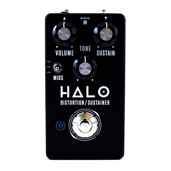
PROJECT NAME
HALO
BASED ON
Electro-Harmonix Big Muff Pi
EFFECT TYPE
Distortion / Sustainer, Fuzz
PROJECT SUMMARY
One of the most classic guitar effects of all time, its sound falls somewhere between a distortion effect
and a fuzz with an incredibly long sustain.
This documentation is for the kit version of the project. If you purchased the PCB by itself, please
use the
PCB-only version
are completely different due to the specialized parts and assembly methods used in the kit.
HALO DISTORTION/SUSTAINER
VOLUME
MIDS
DISTORTION SUSTAIN ER
IMPORTANT NOTE
of the documentation instead. The circuit is the same, but the instructions
BUILD DIFFICULTY
Easy
DOCUMENT VERSION
1.0.0 (2018-11-22)
9V
TONE
SUSTAIN
1
Advertisement
Table of Contents

Related Manuals for Aion Electronics HALO


Summary of Contents for Aion Electronics HALO
- Page 1 This documentation is for the kit version of the project. If you purchased the PCB by itself, please use the PCB-only version of the documentation instead. The circuit is the same, but the instructions are completely different due to the specialized parts and assembly methods used in the kit. HALO DISTORTION/SUSTAINER...
-
Page 2: Table Of Contents
19 Enclosure Layout: Panel Mounts (cont.) 20 Enclosure Layout: Main & Footswitch PCBs 21 Enclosure Layout: Input/Output PCB 22 Final Testing & Assembly 23 Schematic 24 Full Parts List 25 Troubleshooting Information 26 Support & Resale Terms 27 Legal Information & Document Revisions HALO DISTORTION/SUSTAINER... -
Page 3: Introduction
It’s recommended to read through all of the instructions before you start, particularly if you’ve never built a pedal before. If you familiarize yourself with the entire process ahead of time and you know what the goal looks like, each step will make more sense. Now, on to the fun stuff! HALO DISTORTION/SUSTAINER... - Page 4 If you find that any parts are missing or damaged, please fill out the Missing Parts form. Film Capacitors Resistors NAME NAME 100R 100n Electrolytic Capacitors NAME 100uF MLCC Capacitors NAME 100k 470pF (marked “471”) 390k 100n (marked “104”) 470k Diodes Transistors NAME 1N5817 NAME 1N914 2N5088 HALO DISTORTION/SUSTAINER...
- Page 5 4-strand wire assembly, 108mm DC jack 3-pin wire assembly header Input/output jack 4-pin wire assembly header Mounting nut, jack, 0.54" Outer washer, jack, 0.6" Lock washer, jack, 0.5" (thin) Enclosure Enclosure screws PCB, main circuit PCB, footswitch PCB, input/output/DC HALO DISTORTION/SUSTAINER...
-
Page 6: Tools Needed
The tip should used to tighten the dress nut to avoid lot of pedals! be no more than 0.1” (2.5mm) wide. scratching or denting it (which can happen with metal tools). HALO DISTORTION/SUSTAINER... -
Page 7: Component Identification
Some voltage regulators It’s recommended to use a also look like this. They may also look like this. razor blade to separate have more than 8 legs. these cleanly. WIRE ASSEMBLY WIRE ASSEMBLY HEADER DC JACK LED BEZEL HALO DISTORTION/SUSTAINER... -
Page 8: Hardware Identification
TOGGLE SWITCH MOUNTING NUT DRESS NUT LOCK WASHER DIAMETER: 0.36” / 9.1mm DIAMETER: 0.375” / 9.5mm DIAMETER: 0.4” / 10.1mm FOOTSWITCH MOUNTING NUT DRESS NUT LOCK WASHER DIAMETER: 0.6” / 15.2mm DIAMETER: 0.77” / 19.6mm DIAMETER: 0.6” / 15.2mm HALO DISTORTION/SUSTAINER... -
Page 9: Pcb Assembly Overview
PCB is upside-down, everything is making contact with the work surface and is held in place. So, you will start by populating the resistors (the lowest-profile components), followed by the diodes, sockets, film capacitors, and finally the electrolytic capacitors. HALO DISTORTION/SUSTAINER... -
Page 10: Resistors
15 to 20 resistors at a time or the bottom of the board will get too crowded. If this is your first time soldering, watch tutorial videos on YouTube and make sure you get it down before you begin. You don’t want to practice or experiment on this board! HALO DISTORTION/SUSTAINER... -
Page 11: Diodes
1N5817 1N914 1N914 1N914 1N914 Next, you’ll populate the diodes. Diodes are polarized, so make sure to identify the polarity band (which indicates the “cathode”, or negative side) and match the band to the footprint on the PCB. HALO DISTORTION/SUSTAINER... -
Page 12: Transistors
Since the transistors are used in a gain-limited application, they don’t need to be selected for any particular characteristics, and sockets are not necessary. You can just solder them directly to the board. Bend the outer leads to hold it in place on the board. Then, solder them and clip the leads. HALO DISTORTION/SUSTAINER... -
Page 13: Capacitors (Non-Polarized)
2. Find the two exposed rectangular pads to the left of CX3 and solder them together. They are close enough that it should be easy to overflow the solder from one pad to the other. Please note that if CX3 is not jumpered, the effect will not work. HALO DISTORTION/SUSTAINER... -
Page 14: Wire Headers
They do fit pretty tightly in the holes, though, so press firmly. There’s also a 4-pin header on the I/O board that we will do in a later step. HALO DISTORTION/SUSTAINER... -
Page 15: Capacitors (Polarized)
(i.e. they will only work in one direction), so note the vertical mark that indicates the negative side. The longer leg is positive and fits in the square pad. This is the last of the on-board components. HALO DISTORTION/SUSTAINER... -
Page 16: Footswitch Pcb
BLUE MARKING Once all three wire assemblies are soldered, set the footswitch PCB aside. We’ll solder the actual footswitch and LED in a later step. HALO DISTORTION/SUSTAINER... -
Page 17: Input/Output Pcb
Red is positive (+), black is negative (-). After soldering, pull it tight. For even more strain relief, you can thread the snap through the loop to form a knot. (not shown) HALO DISTORTION/SUSTAINER... -
Page 18: Enclosure Layout: Panel Mounts
You’ll need to hold the bezel in place when OUTER WASHER tightening the nut. The top of the bezel is fairly MOUNTING NUT sharp, so try using a rubber band for grip instead of pressing your finger against the bottom. HALO DISTORTION/SUSTAINER... -
Page 19: Enclosure Layout: Panel Mounts (Cont.)
MOUNTING NUT LOCK WASHER BEZEL MOUNTING NUT & LED The dress nut acts as a mounting nut, unlike the footswitch dress nut. Use flat- nose pliers on the flat sides of the nut to tighten securely. FOOTSWITCH 125B HALO DISTORTION/SUSTAINER... -
Page 20: Enclosure Layout: Main & Footswitch Pcbs
“box it before you rock it”. If you’ve read the documentation carefully and followed all the instructions, there’s a good chance you will get it right the first time! HALO DISTORTION/SUSTAINER... -
Page 21: Enclosure Layout: Input/Output Pcb
Note the use of two mounting nuts on each of the jacks, one inside and one outside. The inner nut acts as a spacer to set the DC jack flush with the outside of the enclosure. The inner nuts should be threaded as far down as they can go. MOUNTING NUT OUTER WASHER LOCK WASHER MOUNTING NUT 125B HALO DISTORTION/SUSTAINER... -
Page 22: Final Testing & Assembly
Last, just close the panel on the back using the four screws. Before that, though, grab a permanent marker and write your name and the completion date on the inside of the back panel. This is an accomplishment! HALO DISTORTION/SUSTAINER... -
Page 23: Schematic
Mid switch: 1 (A1-2, B1-2): Stock (Mid Scoop) 1N5817 2 (A2-3, B1-2): Flat Mids 100uF 100n 3 (A2-3, B2-3): Mid Hump 1N914 1N914 MIDSA 1N914 1N914 100n 100n CX3_BYP 470pF 2N3904 470pF 470pF 470k 470k 470k 2N3904 2N3904 2N3904 HALO DISTORTION/SUSTAINER... -
Page 24: Full Parts List
3n9 film 10n film 1N914 470pF MLCC 10n film 3n9 film 1N914 100n film 100n film jumper Transistors Potentiometers Switches PART VALUE PART VALUE PART 2N5088 Volume 100kA DPDT on-on-on 2N5088 Sustain 100kB 3PDT stomp 2N5088 Tone 100kB 2N5088 HALO DISTORTION/SUSTAINER... -
Page 25: Troubleshooting Information
0.5V higher or lower than these listed voltages, it’s a good indicator of an issue and the voltages can help you or someone else narrow it down. VOLTAGE VOLTAGE VOLTAGE VOLTAGE 0.03V 0.03V 0.03V 1.02V 0.70V 0.70V 0.69V 1.70V 4.68V 4.73V 4.69V 4.87V HALO DISTORTION/SUSTAINER... - Page 26 “goop” the PCB or otherwise obscure the source. In other words: you don’t have to go out of your way to advertise the fact that you use Aion FX kits, but please don’t go out of your way to hide it. The guitar effects industry needs more transparency, not less! HALO DISTORTION/SUSTAINER...
- Page 27 All content and graphics in this document are original works and are copyrighted by Aion FX and may not be used without permission. DOCUMENT REVISIONS 1.0.0 (2018-11-22) Initial release. HALO DISTORTION/SUSTAINER...
Need help?
Do you have a question about the HALO and is the answer not in the manual?
Questions and answers