Table of Contents
Advertisement
Quick Links
Advertisement
Table of Contents

Summary of Contents for Riello MultiCOM 392
- Page 3 NTRODUCTION Thank you for choosing our product. The accessories described in this manual are of the highest quality, carefully designed and built in order to ensure excellent performance. This manual contains detailed instructions on how to install and use the product. This manual must be stored in a safe place and CONSULTED BEFORE USING THE DEVICE for proper usage instructions as well as maximum performance from the device itself.
- Page 4 NVIRONMENTAL PROTECTION Our company devotes abundant resources to analysing environmental aspects in the development of its products. All our products pursue the objectives defined in the environmental management system developed by the company in compliance with applicable standards. Hazardous materials such as CFCs, HCFCs or asbestos have not been used in this product. When evaluating packaging, the choice of material has been made favouring recyclable materials.
-
Page 5: Table Of Contents
ONTENTS DESCRIPTION NPUTS UTPUTS SERIES MST / MSM / MCT / MCM UMPER SETTINGS ON INTERFACE BOARD OF THE AFETY TESTS COM 392 UMPER SETTINGS AND INSTALLATION OF THE ULTI ONFIGURATION SERIES C1T / C1M UMPER SETTINGS AND INSTALLATION ONFIGURATION SERIES GMI UMPER SETTINGS AND INSTALLATION ONFIGURATION... -
Page 7: Description
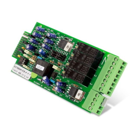
DESCRIPTION MultiCOM 392 is a device that, inserted in the proper slot of the UPS, provides 8 configurable dry contact outputs and up to four inputs for the control and monitoring of the UPS. The device is compatible with the following UPS series: •... -
Page 8: Inputs
NPUTS The four inputs, IN1 / IN2 / IN3 / SWMB, can be configurable or not according to different UPS series. Check the features that are compatible and the default configuration in the chapter dedicated to your UPS model. Some UPS may not handle all inputs. UTPUTS For all UPS series, each of the eight outputs (OUT1 –... -
Page 9: Series Mst / Msm / Mct / Mcm
- MST / MSM / MCT / MCM - SERIES MST / MSM / MCT / MCM For series MST / MSM / MCT / MCM, MultiCOM 392 is compatible only if the UPS is provided with the interface board mounted B0056 Rev.01C / B0056 Rev.02C or higher. - Page 10 - MST / MSM / MCT / MCM - OPEN OPEN CLOSED (DEFAULT) for using the REMOTE OFF function through the AS400 port of the UPS OPEN for using the REMOTE OFF function through IN2 of the MultiCOM 392 OPEN CLOSED...
-
Page 11: Safety Tests
- MST / MSM / MCT / MCM - AFETY TESTS CAUTION ALL OPERATIONS DESCRIBED IN THIS CHAPTER MUST ONLY BE CARRIED OUT BY PERSONNEL WHO ARE QUALIFIED AND PROPERLY TRAINED The tests described below should be performed after the UPS is completely closed with the wrapping and all the panels. In addition, all operations must be carried out with the UPS off and completely disconnected from the mains, batteries and any other equipment. -
Page 12: Jumper Settings And Installation Of The Multi Com 392
- MST / MSM / MCT / MCM - COM 392 UMPER SETTINGS AND INSTALLATION OF THE ULTI Set the jumper of the MultiCOM 392 referring to the following table and image. OPEN (DEFAULT) for using the REMOTE OFF function through the AS400 port of the UPS CLOSED... - Page 13 - MST / MSM / MCT / MCM - MultiCOM 392 must be inserted only in the UPS slot dedicated to the contacts boards: “AUX RELAY SLOT”. ▪ Remove the cover of the UPS slot dedicated to the contacts boards (AUX RELAY SLOT) by removing the two retaining screws.
-
Page 14: Configuration
- MST / MSM / MCT / MCM - ONFIGURATION MultiCOM 392 can be configured using the configuration software of the UPS. Before setting the input/output, you must select “Multicom 392 [8out]” for I/O card model. INPUT DESCRIPTION REMOTE ON: By closing the contact for at least 3 seconds, the UPS will switch on. - Page 15 - MST / MSM / MCT / MCM - For each of the eight outputs can be selected: the associated event (Output mode), the operating logic of the relay (Logic) and a delay (in seconds) in reporting the event. OUTPUT CONTACTS DEFAULT CONFIGURATION Output Output mode Logic...
-
Page 16: Series C1T / C1M
- C1T / C1M - SERIES C1T / C1M UMPER SETTINGS AND INSTALLATION Set the jumpers of the MultiCOM 392 referring to the following table and image. CLOSED OPEN OPEN OPEN OPEN... - Page 17 - C1T / C1M - MultiCOM 392 must be inserted only in the CSS slot dedicated to the contacts boards: “AUX RELAY SLOT”. ▪ Remove the cover of the CSS slot dedicated to the contacts boards (AUX RELAY SLOT) by removing the two retaining screws.
-
Page 18: Configuration
- C1T / C1M - ONFIGURATION MultiCOM 392 can be configured using the configuration software of the CSS. Before setting the input/output, you must select “Multicom 392 [8out]” for I/O card model. INPUT DESCRIPTION REMOTE ON: By closing the contact for at least 3 seconds, the UPS will switch on. - Page 19 - C1T / C1M - For each of the eight outputs can be selected: the associated event (Output mode), the operating logic of the relay (Logic) and a delay (in seconds) in reporting the event. OUTPUT CONTACTS DEFAULT CONFIGURATION Output Output mode Logic Delay (s)
-
Page 20: Series Gmi
- GMI - SERIES GMI UMPER SETTINGS AND INSTALLATION Set the jumpers of the MultiCOM 392 referring to the following table and image. OPEN OPEN OPEN OPEN OPEN... - Page 21 - GMI - MultiCOM 392 must be inserted only in the UPS slot dedicated to the contacts boards: “AUX RELAY SLOT”. ▪ Remove the cover of the UPS slot dedicated to the contacts boards (AUX RELAY SLOT) by removing the two retaining screws.
-
Page 22: Configuration
- GMI - ONFIGURATION MultiCOM 392 can be configured using the configuration software of the UPS. Before setting the input/output, you must select “Multicom 392 [8out]” for I/O card model. INPUT DESCRIPTION REMOTE ON: By closing the contact for at least 3 seconds, the UPS will switch on. - Page 23 - GMI - For each of the eight outputs can be selected: the associated event (Output mode), the operating logic of the relay (Logic) and a delay (in seconds) in reporting the event. OUTPUT CONTACTS DEFAULT CONFIGURATION Output Output mode Logic Delay (s) OUT 1...
-
Page 24: Series S3T / S3M / S3U
- S3T / S3M / S3U - SERIES S3T / S3M / S3U UMPER SETTINGS AND INSTALLATION Set the jumpers of the MultiCOM 392 referring to the following table and image. CLOSED OPEN OPEN OPEN OPEN... - Page 25 - S3T / S3M / S3U - MultiCOM 392 must be inserted only in the UPS slot named “COMMUNICATION SLOT 2”. ▪ Remove the cover of the UPS slot dedicated to the contacts boards (COMMUNICATION SLOT 2) by removing the two retaining screws.
-
Page 26: Configuration
MultiCOM 392 must be configured using the configuration software of the UPS. By default no function is associated to input/output and they have to be configured via the UPS configuration software. Before setting the input/output, you must select MC392 (MultiCOM 392) for Communication slot 2. - Page 27 - S3T / S3M / S3U - IN 1, IN 2 and IN 3 are named “Input1-opt”, “Input2-opt” and “Input3-opt” in configuration software. SWMB is not managed in S3T / S3M / S3U. For each input can be selected: the associated function (Mode) and the operating logic of the contact (Logic). INPUT CONTACTS DEFAULT CONFIGURATION INPUT CONFIGURABLE...
- Page 28 - S3T / S3M / S3U - OUT 1, … ,OUT8 are named “Output1-opt”, … ,“Output8-opt” in configuration software. For each of the eight outputs can be selected: the associated event (Output mode), the operating logic of the relay (Logic) and a delay (in seconds) in reporting the event. OUTPUT CONTACTS DEFAULT CONFIGURATION OUTPUT CONFIGURABLE...
- Page 29 - S3T / S3M / S3U - EXAMPLE 1 - if you set an output in this way: Output mode Logic Delay (s) Battery working Relay ON the relative contact will be: UPS working by mains UPS in battery working mode EXAMPLE 2 - if you set an output in this way: Output mode Logic...
-
Page 30: Series Mpw / Mpx
- MPW / MPX - SERIES MPW / MPX NOTE: refer also to the MPW /MPX Advanced configuration manual for further information. UMPER SETTINGS AND INSTALLATION Set the jumpers of the MultiCOM 392 referring to the following table and image. CLOSED OPEN OPEN... - Page 31 Remove the cover of the slot dedicated to the contacts boards (RELAY SLOT) by removing the two retaining screws. ▪ Wire appropriately MultiCOM 392. ▪ Insert MultiCOM 392 in the slot dedicated to the contacts card (RELAY SLOT). ▪ Fix the cover provided with the MultiCOM 392 using the screws previously removed.
-
Page 32: Configuration
By default no function is associated to input/output and they have to be configured via the UPS configuration software. Before setting the input/output, you must select “Multicom 392 [8out/4in]” for I/O card model. For each input can be selected: the associated function (Input mode). - Page 33 - MPW / MPX - For each of the eight outputs can be selected: the associated event (Output mode), the operating logic of the relay (Logic) and a delay (in seconds) in reporting the event. OUTPUT CONTACTS DEFAULT CONFIGURATION Output Output mode Logic Delay (s)
- Page 36 0MNACCMC9ENUD...
Need help?
Do you have a question about the MultiCOM 392 and is the answer not in the manual?
Questions and answers