Table of Contents
Advertisement
Quick Links
Assembly instruction
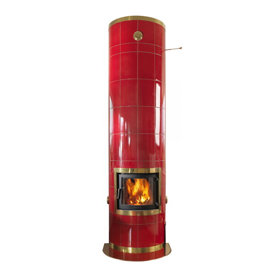
STUDIO
tiled stove (series 400)
Model....................................
Content
Tests and approvals ............................ 2
Explanation of symbols / foreword ...... 3
Body
Preparations ...................................... 4
Important measurements...................... 5
Overall installation sequence ............... 6
Assembly ..................................... 7-17
Tiling preparation and assembly ... 17-18
Tiling plan ....................................... 19
Cassette installation ..................... 20-23
Fan installation ................................ 23
2012-07-02
Advertisement
Table of Contents

Subscribe to Our Youtube Channel
Related Manuals for GABRIEL KAKELUGNAR STUDIO 400 Series


Summary of Contents for GABRIEL KAKELUGNAR STUDIO 400 Series
-
Page 1: Table Of Contents
Assembly instruction STUDIO tiled stove (series 400) Model........Content Tests and approvals ......2 Explanation of symbols / foreword ..3 Body Preparations ........4 Important measurements...... 5 Overall installation sequence ....6 Assembly ........7-17 Tiles and cassette Tiling preparation and assembly ... 17-18 Tiling plan ........ -
Page 2: Tests And Approvals
Tests and approvals GABRIEL KERAMIK AB CE-marking The Gabriel tiled stoves are Swedish products and fulfi l the requirements for CE-marking, meaning that they comply with EU health, environmental and Gabriel Keramik AB safety requirements. CE stands for Communaútes Strandavägen 62 SE-380 52 Timmernabben, Sweden Européennes. -
Page 3: Explanation Of Symbols/Foreword
Explanation of symbols/foreword GABRIEL KERAMIK AB Safety instructions Read these instructions carefully before Make sure prior to the assembly that the starting the assembly. Incorrect assembly building permit is approved and that the can cause serious damage and fire risk. local chimney sweep has approved the installation. -
Page 4: Preparations
Preparations GABRIEL KERAMIK AB Measurement for 150 mm flue pipe connection ø In a corner Combustible wall min. 75 mm Ø 150 Top plate 318 mm Against a straight wall Combustible wall min. 75 mm min. 75 mm Ø 150 Ø... -
Page 5: Important Measurements
Important measurements • STUDIO GABRIEL KERAMIK AB Control and guide measurements (all measurements in mm) = Control measurement Outer section 2330 Inner section 2088 1978 1820 1660 1561 1500 1375 1340 joints 1189 1180 1020 1003 Floor level * 1–17 shows the numbers of all parts, see page 6. Corner / wall position In a corner Against a straight wall... -
Page 6: Overall Installation Sequence
Overall installation sequence GABRIEL KERAMIK AB Start A 6 • STUDIO... - Page 7 Assembly GABRIEL KERAMIK AB Mark on the floor exactly where the stove is going to be placed. Also Before starting the assembly, mark the direction of the opening. make sure that the support is The example on the picture shows approved according to your 45°...
- Page 8 Assembly GABRIEL KERAMIK AB Set the firebox block (2) with mortar. Mark the centre line on the first block, it will help you to position the opening and the soot hole correctly. 406 mm Set the outer block (3) with mortar. The opening shall face the 45°- marking on the floor (step 1).
- Page 9 Assembly GABRIEL KERAMIK AB Set the firebox (8) with mortar. The firebox block may not touch the outer rings (the firebox block must be allowed to expand freely without affecting the outer ring). Level vertically and horizontally. Push the firebox block backwards as much as possible.
- Page 10 Assembly GABRIEL KERAMIK AB Set the outer ring (5) with mortar. Level vertically and horizontally. Set the outer ring (6) with mortar. Check that the height is within the tolerane (508 mm). For a better joint, wipe the contact surfaces with a squeezed sponge, then brush with a wet radiator brush.
- Page 11 Assembly GABRIEL KERAMIK AB Set the fourh firebox block (8A) on top of the third one. Make sure that no mortar falls between the blocks. Level vertically and horizontally. Cut off the insulation. 953 mm Note! Clean off mortar leftoers. Plain with a radiator brush.
- Page 12 Assembly GABRIEL KERAMIK AB Place the inner block (10) on top of the firebox block without mortar joint. Make sure that this and the following blocks are in level and do not ignore any irregularities. Seal/isulate the hollow space under the outer ring as indicated. Carefully centre and set the outer rings (7).
- Page 13 Assembly GABRIEL KERAMIK AB Set the outer ring (7) in mortar. Level vertically and horizontally. Set the “church roof” (11). Level vertically and horizontally. Seal with 2-3 mm insulation. Make sure that no mortar falls between the firebox block and the outer ring. Set the flame protection block (13) with mortar.
- Page 14 Assembly GABRIEL KERAMIK AB Set the outer ring (7) with mortar. Level vertically and horizontally. Set the outer ring (7) with mortar. Level vertically and horizontally. Set the outer ring (7) with mortar. Level vertically and horizontally. 1980 mm 14 • STUDIO...
- Page 15 Assembly GABRIEL KERAMIK AB Set the divider block (12) and the flame protection block (13) with mortar. Level vertically and horizontally. Set the next two divider and flame protection blocks (12 and 13) with mortar. Level vertically and horizontally. The divider block (12) and flame protection block (13) must be 2–4 mm below the outer ring to allow the inner body to expand.
- Page 16 Assembly GABRIEL KERAMIK AB Set the top lid (14) with mortar. Level vertically and horizontally. Ø 125 mm Set the damper lid (15) with mortar. Level vertically and horizontally. Set the damper frame with a thin bed of mortar and make sure the damper runs freely.
-
Page 17: Assembly
Assembly GABRIEL KERAMIK AB Render and brush the soot channel surfaces, also the downside of the top lid when it is installed. Top connected chimney Set the top lid (17) with mortar and make sure it is in level with the Ø... -
Page 18: Tiling Preparation And Assembly
Tiling preparations and assembly GABRIEL KERAMIK AB IMPORTANT STEPS PRIOR TO TILING • Mark the centre line. • Check that the floor is level. • Check the body surface. Is it vertical? Be aware that you must compensate for any irregularities. •... -
Page 19: Tiling Plan
Tiling plan GABRIEL KERAMIK AB Kakelsats Studio Decor steel band 50 mm 310 x 210 mm 100 x 210 mm Decor steel band 30 mm STUDIO • 19... - Page 20 Cassette installation (Studio, Studio2 and round tiled stove) GABRIEL KERAMIK AB 80/125 80/100 Outdoor cumbustion air inlet Indoor cumbustion air inlet Mount the reduction flange to the flexible tube and Mount the reduction flange to the flexible tube and connect to the flange for inlet air through the floor. connect to the flange for inlet air through the base.
-
Page 21: Cassette Installation
Cassette installation GABRIEL KERAMIK AB Pass the flexible tube through the cassette bottom and fit it over the connecting flange. Fasten the flange plate. Mount the damper in the bottom of the cassette, do not forget the cotter pins. Make sure the damper has a free action. - Page 22 Cassette installation GABRIEL KERAMIK AB Place the vermiculite plate in the bottom. Protect the brass frame and tiles around the cassette with masking tape to ensure a neat silicon seal. 20mm Pull out the cassette approx. 20 mm and apply silicon just inside the edge around the brass frame, then push the cassette back in.
-
Page 23: Fan Installation
Cassette installation GABRIEL KERAMIK AB Insert the steel plate vertically over the edge of the cassette. Turn the plate horizontally and pull it backwards firm and tight against the top of the fire box block so that it at the same time is fitted tight between the cassete and the body as shown in picture 3 and 4. - Page 24 GABRIEL KERAMIK AB www.gabrielkakelugnar.se Tel. +46 (0)499 233 00...
Need help?
Do you have a question about the STUDIO 400 Series and is the answer not in the manual?
Questions and answers