Advertisement
Table of Contents
- 1 Table of Contents
- 2 Tests and Approvals
- 3 Explanation of Symbols/Foreword
- 4 Preparations
- 5 Important Measurements
- 6 Overall Installation Sequence
- 7 Assembly
- 8 Assembly
- 9 Tiling - Preparations
- 10 Tiling - Assembly
- 11 Cassette Installation
- 12 Cassette Installation
- 13 Fan Installation
- Download this manual
TMS 2015-10-15
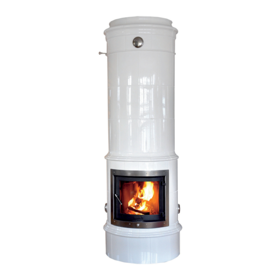
Assembly instruction
Round tile stoves
Model:
G310 Kungsholm
G315 Karl-Johan
G320 Drottningholm
G340 Gabriel
G350 Duvemåla
G360 Tillinge
Contents
Tests and approvals ............................ 2
Explanation of symbols / foreword ...... 3
Body
Preparations ...................................... 4
Important measurements...................... 5
Overall installation sequence ............... 6
Assembly ..................................... 7-17
Tiles and cassette
Tiling - preparations .......................... 18
Tiling - assembly.......................... 19-23
Cassette installation ..................... 24-27
Fan installation ................................ 27
Advertisement
Table of Contents

Related Manuals for GABRIEL KAKELUGNAR G310 Kungsholm


Summary of Contents for GABRIEL KAKELUGNAR G310 Kungsholm
-
Page 1: Table Of Contents
Assembly instruction Round tile stoves Model: G310 Kungsholm G315 Karl-Johan G320 Drottningholm G340 Gabriel G350 Duvemåla G360 Tillinge Contents Tests and approvals ......2 Explanation of symbols / foreword ..3 Body Preparations ........4 Important measurements...... 5 Overall installation sequence ....6 Assembly ........ -
Page 2: Tests And Approvals
Slow heat release appliance (SHRA) fired by solid fuel Type & serial no. Type & serial no. DECLARATION of PERFORMANCE (DoP) Gabriel Kakelugnar 300-serie (G310 - G360) Gabriel Kakelugnar 300-serie (G310 - G360) No. G310-G360-CPR-150615 DECLARATION of PERFORMANCE (DoP) Product type:... -
Page 3: Explanation Of Symbols/Foreword
Explanation of symbols/foreword GABRIEL KERAMIK AB Safety instructions Make sure prior to the assembly that the Read these instructions carefully before starting the assembly. Incorrect assembly building permit is approved and that the local chimney sweep has approved the can cause serious damage and fire risk. installation. -
Page 4: Preparations
Preparations GABRIEL KERAMIK AB Measurement for 150 mm flue pipe connection ø In a corner Combustible wall min. 50 mm Ø 150 mm Top plate 318 mm Against a straight wall Combustible wall min. 50 mm min. 50 mm Ø 150 mm Ø... -
Page 5: Important Measurements
Important measurements • ROUND GABRIEL KERAMIK AB Control and guide measurements (all measurements in mm) = Control measurement Outer section Inner section 1896 1795 1587 1516 1379 1171 joints Floor level * 1–17 shows the numbers of all parts, see page 6. Distance to wall (50 mm) Distance to ceiling (50 mm) In a corner... -
Page 6: Overall Installation Sequence
Preparations GABRIEL KERAMIK AB Start A 6 • ROUND... -
Page 7: Assembly
Assembly GABRIEL KERAMIK AB Mark on the floor exactly where the Before starting the assembly, stove is going to be placed. Also make sure that the support is mark the direction of the opening. approved according to your The example on the picture shows building permit and that it is in 45°... - Page 8 Assembly GABRIEL KERAMIK AB Set the firebox block (2) with mortar. Mark the centre line on the first block, it will help you to position the opening and the soot hole correctly. 338 mm Set the outer block (3) with mortar. The opening shall face the 45°- marking on the floor (figure 1).
- Page 9 Assembly GABRIEL KERAMIK AB Set the firebox (8) with mortar. The firebox block may not touch the outer block (the firebox block must be allowed to expand freely without affecting the outer block). Level vertically and horizontally. Push the firebox block backwards as much as possible.
- Page 10 Assembly GABRIEL KERAMIK AB Set the outer block (5) with mortar. Level vertically and horizontally. Check that the height is within the tolerane (500 mm) 5 0 0 m m Set the outer block (6) with mortar. For a better joint, wipe the contact surfaces with a squeezed sponge, then brush with a wet radiator...
- Page 11 Assembly GABRIEL KERAMIK AB Set the fourh firebox block (8A) on top of the third one. Make sure that no mortar falls between the firebox block and the outer block. 953 mm Make sure that no mortar falls between the firebox block and the outer block.
- Page 12 Assembly GABRIEL KERAMIK AB Place the inner block (10) on top of the firebox block without mortar joint. Make sure that this and the following blocks are in level and do not ignore any irregularities. Seal/isulate the hollow space under the outer ring as indicated. Carefully centre and set the outer blocks (7).
- Page 13 Assembly GABRIEL KERAMIK AB Set the outer block (7) in mortar. Level vertically and horizontally. Set the outer block (7) in mortar. Level vertically and horizontally. Set the “church roof” (11). Level vertically and horizontally. Seal with 2-3 mm insulation. Make sure that no mortar falls between the firebox block and the outer block.
- Page 14 Assembly GABRIEL KERAMIK AB Set the flame protection block (13) with mortar. Level vertically and horizontally. Set the outer block (7) with mortar. Level vertically and horizontally. Set the outer block (7) with mortar. Level vertically and horizontally. 1898 mm 14 •...
- Page 15 Assembly GABRIEL KERAMIK AB Set the divider block (12) and the flame protection block (13) with mortar. Level vertically and horizontally. Set the divider block (12) and the flame protection block (13) with mortar. Level vertically and horizontally. The divider block (12) and flame protection block (13) must be 2-4 mm below the outer block to allow the inner body to expand.
- Page 16 Assembly GABRIEL KERAMIK AB Set the top lid (14) with mortar. Level vertically and horizontally. Ø 125 mm Set the damper lid (15) with mortar. Level vertically and horizontally. Set the damper frame with a thin bed of mortar and make sure the damper runs freely.
-
Page 17: Assembly
Assembly GABRIEL KERAMIK AB Render and brush the soot channel surfaces, also the downside of the top lid when it is installed. Top connected chimney Set the top lid (17) with mortar Ø 150 mm and make sure it is in level with the underlying flue gas hole. -
Page 18: Tiling - Preparations
Tiling and preparations GABRIEL KERAMIK AB Assembly tiles and cassette IMPORTANT STEPS PRIOR TO TILING • Mark the centre line. • Check that the floor is level. • Check the body surface. Is it vertical? Be aware that you must compensate for any irregularities. -
Page 19: Tiling - Assembly
Assembly - tiles GABRIEL KERAMIK AB Level and mark the centre line from the top down to the base. (Devide the firebox into two equal halves). 45° 45° Fix the first tile exactly in the centre of the marking as shown. Apply as much adhesive to fix the tile approx. - Page 20 Assembly - tiles GABRIEL KERAMIK AB Set tiles around the base starting from the centre. Level vertically and horizontally. Mount the grate and the last tile. Each tile list (foot simms) is manufactued with a sup- port at the back, which must carefully be removed to fit in properly.
- Page 21 Assembly - tiles GABRIEL KERAMIK AB Apply the tiles intended for the soot holes. Level vertically and horizon- tally. Continue the tiling around the firebox opening and then around the firebox. It is important to level the tiles vertically and horizon- tally to be able to install the cassette in exact position.
- Page 22 Assembly - tiles GABRIEL KERAMIK AB Complete the centre section by tiling around the firebox. Start from the bottom. Level vertically and horizontally. Each centric tile list is manu- factued with a support at the back, which must carefully be removed to fit in properly. Apply two centric tile lists (use a somewhat dryer adhesive).
- Page 23 Assembly - tiles GABRIEL KERAMIK AB Apply the 66 cm tiles. Start with the row above the mid simms (wasteline lists). Work from the centre towards the sides. Repeat the following rows, always level vertically and horizontally. Before applying the frieze, carefully remove the support at the back.
-
Page 24: Cassette Installation
Cassette installation GABRIEL KERAMIK AB Outdoor cumbustion air inlet Indoor cumbustion air inlet Mount the reduction flange to the flexible tube and Mount the reduction flange to the flexible tube and connect to the flange for inlet air through the floor. connect to the flange for inlet air through the base. - Page 25 Cassette installation GABRIEL KERAMIK AB Pass the flexible tube through the cassette bottom and fit it over the connecting flange. Fasten the flange plate. Mount the damper in the bottom of the cassette, do not forget the cotter pins. Make sure the damper has a free action.
- Page 26 Cassette installation GABRIEL KERAMIK AB Place the vermiculite plate in the bottom. Protect the brass frame and tiles around the cassette with masking tape to ensure a neat silicon seal. 20mm Pull out the cassette approx. 20 mm and apply silicon just inside the edge around the brass frame, then push the cassette back in.
-
Page 27: Fan Installation
Cassette installation GABRIEL KERAMIK AB Insert the steel plate vertically over the edge of the cassette. Turn the plate horizontally and pull it backwards firm and tight against the top of the fire box block so that it at the same time is fitted tight between the cassete and the body as shown in picture 3 and 4. - Page 28 Low temperature flue gas outlet The traditional 5-channel flue gas principle is still incomparable Inner core Outer mantle Expansion area Heat accumulating, dense, fire-resistant material for long-lasting heat radiation Fan controlled direct heat through channels in the hot air cassette for efficient heat circulation Airflow on the inside keeps the glass cleaner...
Need help?
Do you have a question about the G310 Kungsholm and is the answer not in the manual?
Questions and answers