Table of Contents
Advertisement
Quick Links
Assembly instruction
TMS 2015-10-15
All manuals and user guides at all-guides.com
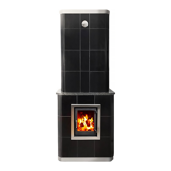
AVANTI tile stoves
Model:
G860 Avanti Black
G861 Avanti White
G862 Avanti Special
Contents
Tests and approvals ......................... 2
Body
Preparations ................................... 4
Important measurements................... 5
Overall installation sequence ............ 6
Assembly ...................................7-18
Radiation plate installation ............. 19
Tiles and cassette
Tiling - preparations ....................... 20
Tiling - assembly............................ 21
Tiling - recommendations ................ 22
Cassette - assembly ....................... 24
Fan installation ............................. 27
Advertisement
Table of Contents

Related Manuals for GABRIEL KAKELUGNAR AVANTI G860


Summary of Contents for GABRIEL KAKELUGNAR AVANTI G860
-
Page 1: Table Of Contents
All manuals and user guides at all-guides.com Assembly instruction AVANTI tile stoves Model: G860 Avanti Black G861 Avanti White G862 Avanti Special Contents Tests and approvals ......2 Explanation of symbols / foreword ... 3 Body Preparations ........4 Important measurements....5 Overall installation sequence .... -
Page 2: Tests And Approvals
Performance Harmonized technical specification Has controled the declarerd performance and released test report nr. 39-8796 G840 Ekeby, G855 Kungälv, Avanti G860, G861 DECLARED PERFORMANCE Essential characteristics Engineering Test Institute, Czech Republic NB1015 Engineering Test Institute, Czech Republic NB1015 has controlled the declared... -
Page 3: Explanation Of Symbols/Foreword
All manuals and user guides at all-guides.com Explanation of symbols/foreword GABRIEL KERAMIK AB Safety instructions Read these instructions carefully before Make sure prior to the assembly that the starting the assembly. Incorrect assembly building permit is approved and that the can cause serious damage and fire risk. -
Page 4: Preparations
All manuals and user guides at all-guides.com Preparations GABRIEL KERAMIK AB Measurement for 150 mm flue pipe connection ø Combustible wall min. 15 mm 150 mm ø 440 mm Measurement for ø 125 mm combustion air inlet connection Combustible wall min. -
Page 5: Important Measurements
All manuals and user guides at all-guides.com Important measurements • AVANTI GABRIEL KERAMIK AB Control and guide measurements (all measurements in mm) = Control measurement Outer mantle 2190 2030 Inner core 1908 1811 1613 1170 1551 1415 1351 Ingen fog No joints 1217 1151... -
Page 6: Overall Installation Sequence
All manuals and user guides at all-guides.com Overall installation sequence GABRIEL KERAMIK AB Start A... -
Page 7: Assembly
All manuals and user guides at all-guides.com Assembly GABRIEL KERAMIK AB Mark on the floor exactly where the stove is going to be placed. The opening for convection air (fan) can be either from the left or Before starting the assembly, right side by turning the baseblock make sure that the support is up-side-down. - Page 8 All manuals and user guides at all-guides.com Assembly GABRIEL KERAMIK AB Set the outer ring (3) with mortar. Seal/insulate between the firebox blocks. Set the outer ring (3a) with mortar. Be aware of the soot hole dimension (ø100 mm) Level vertically and horizontally. For a better joint, wipe the contact surfaces with a squeezed sponge.
- Page 9 All manuals and user guides at all-guides.com Assembly GABRIEL KERAMIK AB Set the outer ring (3) with mortar. Level vertically and horizontally. Make sure there is space for soot hole and flange. 100 mm 100 mm Set the second firebox block (6) on top of the first one.
- Page 10 All manuals and user guides at all-guides.com Assembly GABRIEL KERAMIK AB Set the third firebox block (6) on top the second one. Make sure that no mortar falls between the blocks. Seal with insulation at the front edge of the U-formed blocks.
- Page 11 All manuals and user guides at all-guides.com Assembly GABRIEL KERAMIK AB Set outer ring (3) with mortar. Level vertically and horizontally. Check that the height is within tolerance (550 mm) 550 mm Set outer ring (4). Set the fifth firebox block (6a) on top of the fourth one.
- Page 12 All manuals and user guides at all-guides.com Assembly GABRIEL KERAMIK AB Cut the insulation. Set the top of the firebox block (7) in mortar. Before continuing above the firebox opening, construct a prop to support both the outer ring and the firebox top block as shown in the picture.
- Page 13 All manuals and user guides at all-guides.com Assembly GABRIEL KERAMIK AB Place the inner block (8) on top of the firebox block (7) without mortar joint. Make sure that this and the following blocks are in level and do not ignore any irregularities.
- Page 14 All manuals and user guides at all-guides.com Assembly GABRIEL KERAMIK AB Set outer ring (9) with mortar. Level vertically and horizontally. Set the “church roof” (10). Level vertically and horizontally. Place a thin strip of insulation, 2–3 mm, between the block and outer ring to prevent soot accumulation.
- Page 15 All manuals and user guides at all-guides.com Assembly GABRIEL KERAMIK AB Set outer ring (9) with mortar. Level vertically and horizontally. 1811 mm Set outer ring (9) with mortar. Level vertically and horizontally. Set the “divider” block (12) in mortar. Level vertically and horizontally.
- Page 16 All manuals and user guides at all-guides.com Assembly GABRIEL KERAMIK AB Set the “flame protection” block (11) and the “divider” block (12a) with mortar. Level vertically and horizontally. The “divider” block (12a) and “flame protection” block (11) must be 2-4 mm below the outer ring to leave enough space for the whole inner core to expand upwards.
- Page 17 All manuals and user guides at all-guides.com Assembly GABRIEL KERAMIK AB Set the “damper” lid (14) with mortar. Level vertically and horizon- tally. Check that the height is within the tolerance (2030 2125 mm Set the damper in a bed of mortar and make sure it runs freely.
- Page 18 All manuals and user guides at all-guides.com Assembly GABRIEL KERAMIK AB Set the small lid (16) in mortar. If needed, cut to size for the either of the two flue pipe installations. The supporting pieces (17) shall be adjusted according to the size of the crown tiles.
-
Page 19: Radiation Plate Installation
All manuals and user guides at all-guides.com Radiation plate installation GABRIEL KERAMIK AB The radiation plate installation • Loosen and turn the upper heat plate (19) so that the bent edge is towards the stove body. Screw it together with the lower heat plate (20) as shown. -
Page 20: Tiling - Preparations
All manuals and user guides at all-guides.com Tiling and preparations GABRIEL KERAMIK AB IMPORTANT STEPS PRIOR TO TILING • Mark the centre line (Picture1 page 21) • Check that the floor is level. • Check the body surface. Is it vertical? Be aware that you must compensate for any irregularities. - Page 21 All manuals and user guides at all-guides.com Recommended tiling GABRIEL KERAMIK AB Loda in centrum Applicera fix med tandsp både på stomme och kakel e Loda in centrum Applicera fix med tandspackel Picture 1 Picture 2 både på stomme och kakel enligt bild. Mark the centre Adhesive shall be line...
-
Page 22: Tiling - Recommendations
All manuals and user guides at all-guides.com Recommended tiling GABRIEL KERAMIK AB RECOMMENDATIONS FOR THE TILE SETTING The tiles are marked with letters according to the tile plan. (Do not unpack all the tiles at the same time as they may be mixed up and placed in the wrong position.) To get a nice end result, we recommend to unpack the tiles row by row as you progress following the letter markings on the wrapping (Picture 6, page 23). -
Page 23: Tiling - Assembly
All manuals and user guides at all-guides.com Tiling - Assembly GABRIEL KERAMIK AB Picture 6 Nr.12 Nr.16 Nr.16 Nr.15 Nr.15 Nr.11 Nr.11 Nr.14 Nr.14 Picture 7 Shelf Mortar Nr.1 Nr.2 Nr.3 Nr.9 Nr.10 Nr.4 Nr.5 Nr.6 Start from the center... -
Page 24: Cassette - Assembly
All manuals and user guides at all-guides.com Cassette assembly in round and rectangular tiled stoves GABRIEL KERAMIK AB 80/125 80/100 Outdoor inlet air Indoor inlet air Mount the reduction flange to the flexible tube and Mount the reduction flange to the flexible tube and connect the flange and tube to inlet air through the connect the flange and tube to inlet air through the floor... - Page 25 All manuals and user guides at all-guides.com Cassette assembly in round and rectangular tiled stoves GABRIEL KERAMIK AB Pass the flexible tube through the hole in the cassette bottom and fit it over the connecting flange and fasten the flange plaate. Mount the damper in the bottom of the cassette, do not forget the cotter pins.
- Page 26 All manuals and user guides at all-guides.com Cassette assembly in round and rectangular tiled stoves GABRIEL KERAMIK AB Mount the vermiculite plate in the bottom. NOTE! The cassette is installed in the same way in round and rectancular stoves. Protect the brass frame and tiles around the cassette with sking tape to ensure a neat silicon 20mm...
-
Page 27: Fan Installation
All manuals and user guides at all-guides.com Cassette assembly in round and rectangular tiled stoves GABRIEL KERAMIK AB Insert the steel plate vertically and over the cassete. Turn the plate horizontally and pull it back to be in close contact with thefire box block (7) and at the same time is wedged into the space between the cassette and the body, see... - Page 28 All manuals and user guides at all-guides.com Low temperature flue gas outlet The traditional 5-channel flue gas principle is still incomparable Inner core Outer mantle Expansion area Heat accumulating, dense, fire-resistant material for long-lasting heat radiation Fan controlled direct heat through channels in the hot air cassette for efficient heat circulation Airflow on the inside keeps...
Need help?
Do you have a question about the AVANTI G860 and is the answer not in the manual?
Questions and answers