Table of Contents
Advertisement
Quick Links
Advertisement
Table of Contents

Related Manuals for Murr Elektronik CUBE20S


Summary of Contents for Murr Elektronik CUBE20S
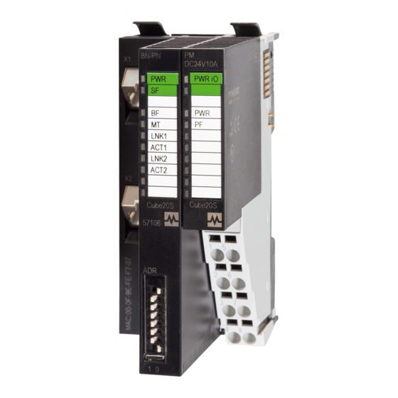
- Page 1 CUBE20S expansion manual Terminal and power module incl. base...
- Page 2 Cube20S terminal module 8x0 V DC 57121 Cube20S terminal module 4x24 V + 0 V 57122 Cube20S power module 24 V DC 57130 Cube20S power module 24 V DC + 5 V 57131 DC / 2 A Document status: Manual number 57120...
-
Page 3: Table Of Contents
Installing the shield bus carrier Disassembling and replacing modules Procedure Replacing the bus node Replacing an expansion module Replacing an electronic module Replacing a module group Installation General notes Spring terminals 7.2.1 Procedure CUBE20S expansion manual 3 / 70 Terminal and power module incl. base... - Page 4 10.3 Art. no. 57131 Power module 24 VDC + 5 VDC/2A 10.3.1 Features 10.3.2 Structure 10.3.3 Supply 10.3.4 Using 10.3.5 Technical Data Appendix 11.1 Accessories 11.2 Glossary 11.3 Legal notes CUBE20S expansion manual 4 / 70 Terminal and power module incl. base...
-
Page 5: Introduction
Introduction / about this document Use of this This document describes the use of the Terminal/power modulesFunction document modules incl. base from the Cube20S of Murrelektronik GmbH. It includes a description of the design, engineering and application. NOTE Translation of the original manual. -
Page 6: Trademarks
Introduction CAUTION! Low-risk danger Failure to observe this warning can lead to mild to moderate injuries. NOTICE Possible material damage Failure to observe the warning may cause damage to the device and/or the system. NOTE Other technical information and notes of Murrelektronik GmbH. RECOMMENDATION Notes with this symbol are recommendations of Murrelektronik GmbH. - Page 7 Introduction STEP Siemens AG TIA Portal Siemens AG User manual 57120_hdb_en_12 7 / 70...
-
Page 8: For Your Own Safety
Qualified personnel is trained or instructed in the respective local valid stan- dards of the safety technology in maintenance and use of the appropriate safety equipment. Intended purpose Designated use The Cube20S system has been designed and manufactured for: communication and process control general control and automation tasks ... -
Page 9: General Safety Instructions
For your own safety General safety instructions Please note: the relevant safety and accident prevention regulations; the EC Directives or other national regulations; generally recognized safety rules; the section 2.5 "EMC installation guidelines". NOTICE Defective device! Improper use of hardware and software can cause damage to the device. - Page 10 For your own safety Components damaged by electrostatic discharge may produce temporary faults in case of temperature changes, vibrations or load changes. Only with a consistent use of protective devices and a responsible compliance of the instructions for use can you avoid malfunctions or failures of the elec- trostatically sensitive equipment.
-
Page 11: Emc Installation Guidelines
For your own safety EMC installation guidelines Industrial use The Cube20S is an electronic device manufactured according to the current state-of-the-art standards. Both the robust mechanical construction and the design of the electronic components make it ideal for industrial use. -
Page 12: Environmentally Friendly Disposal
For your own safety Environmentally friendly disposal Disposal The product can be returned to Murrelektronik GmbH free of charge for dis- posal. The same is true for the original packaging and any batteries or power packs. Any units that have been contaminated with hazardous substances will not be accepted for repair or disposal. -
Page 13: System Description
Bus node Expansion modules Accessories NOTE The use of the Cube20S system is only permitted with a combination of mod- ules from Murrelektronik. Operation together with modules of other manufac- turers is impermissible! User manual 57120_hdb_en_12 13 / 70... - Page 14 System description Bus node Bus interface and power module of the bus node are integrated in one hous- ing. The bus interface is used for connection to a superior bus system. Both bus interface and the electronics of the connected expansion modules are supplied with power via the power module.
- Page 15 safe locking system for fastening on a mounting rail. This locking mechanism allows you to mount your Cube20S system outside the control cabinet and fix the complete sys- tem later in the control cabinet. Electronic module The functionality of an expansion module is defined over the electronic module.
- Page 16 System description Power modules Power modules provide the Cube20S system with power. The power modules are either integrated into the bus node or may be plugged in between the expan- sion modules. Depending on the type of power module, groups of potential can be defined for the 24 V DC power supply, or the electronics supply may be extended by 2 A.
-
Page 17: Hardware Revision
The hardware revision is printed on each Cube20S module. Since a Cube20S module consists of a terminal and an electronic module, the respective hardware revision is printed on both modules. Important for the hardware revision of a Cube20S module is the hardware ... -
Page 18: General Data
General data General data Conformity 2014/30/EU EMC Directive 2011/65/EU RoHS Certifications Certification according to UL Certification according to KC Personal and device protection Degree of protection EN 60529 IP20 Electrical isolation To fieldbus Galvanically decoupled To process level Galvanically decoupled Insulation resistance EN 61131-2 Insulation voltage to reference ground... - Page 19 General data EMC / standards Remarks Emitted interfer- EN 61000-6-4 Class A (industrial environments) ence Immunity Zone B EN 61000-6-2 Industrial environments EN 61000-4-2 8 kV with air discharge (severity grade 3), 4 kV with contact discharge (severity grade 2) EN 61000-4-3 HF irradiation (housing) 80 MHz ...
-
Page 20: Mounting
Mounting Mounting Dimensions Dimensions of the bus node 76.5 46,2 49,2 Fig. 5-1: Dimensions of the bus node in mm Dimensions Expansion module Fig. 5-2: Dimensions of the expansion module in mm Dimensions of the elec- tronic module Fig. 5-3: Dimensions of the electronic module in mm User manual 57120_hdb_en_12 20 / 70... -
Page 21: General Notes
Mounting General notes WARNING! Danger due to electric current! Device and environment in the switch cabinet may carry lethal voltages. Before carrying out any work, make sure that the device and environment are disconnected from the power supply. Observe the relevant safety regulations when handling live devices. -
Page 22: Functional Principle Of The Locking
Mounting 5.2.1 Functional principle of the locking Inserting and locking the module The terminal module has a locking lever at its top. For installation and disassembly, please press this locking lever upwards until it engages audibly. Plug the module to be mounted in the previously plugged-in module. Slide the module with the help of the guide strips at top and bottom onto the DIN rail. -
Page 23: Installing The Din Rail
Mounting Installing the DIN rail Install the DIN rail with the necessary distances (see Fig. 5-5: "Installation distances"). Fig. 5-5: Installation distances User manual 57120_hdb_en_12 23 / 70... -
Page 24: Mounting Of The Bus Node
Mounting Mounting of the bus node To mount the system, start on the left with the bus node. Flap the two locking levers of the bus node upwards (Figure 1). Plug the bus node in the DIN rail (Figure 1). Flap the two locking levers of the bus node downwards (Figure 2). -
Page 25: Installing The Expansion Modules
Mounting Installing the expansion modules Flap the locking lever of the expansion module upwards. Plug the expansion module in the DIN rail. Push the expansion module towards the bus node or the last expansion module. Flap the locking lever of the expansion module downwards. Mount all expansion modules as described. -
Page 26: Replacing An Electronic Module
Mounting Replacing an electronic module Expansion modules Each expansion module consists of a terminal and an electronic module. Terminal module Electronic module Disassembly The electronic module has a locking lever at the bottom. Power-off your system! Press the locking lever upwards for disassembly. To remove the electronic module, pull it out towards the front. -
Page 27: Installing The Bus Cover
Mounting Installing the bus cover Protection of the bus contacts by means of the bus cover Placing the bus cover on the expansion module Prerequisite: The system has been completely mounted. Attach the bus cover to the outermost module. Placing the bus cover on the terminal module ... -
Page 28: Installing The Shield Bus Carrier
Carriers for shield busses, shield busses and cable shield fasteners are not included in the scope of delivery. Installing the carrier Prerequisite: The Cube20S system has been completely mounted. If the DIN rail is flat, break the spacer off the carrier. ... -
Page 29: Disassembling And Replacing Modules
Disassembling and replacing modules Disassembling and replacing modules Procedure NOTE For demounting and exchange of a bus node, a module or a group of modules, due to mounting reasons you always have to remove the electronic module right beside. After mounting it may be plugged again. During disassembly or when replacing bus node, a module or module group, please observe the following: Switch off the system's power supply. -
Page 30: Replacing The Bus Node
Disassembling and replacing modules Replacing the bus node Disassembly CAUTION! Power module and bus interface belong together! If separated, the modules get destroyed. Do not separate power module and bus interface! Switch off the system's power supply! Remove the wiring from the bus node, if any (see section 7 "Installation"). Unlock the electronic module to its right at the bottom. -
Page 31: Replacing An Expansion Module
Disassembling and replacing modules Installing the new bus Flap the locking levers of the bus node upwards. node Plug the bus node in the left module. Slide the bus node with the help of the guide strips onto the DIN rail. Flap the locking levers downwards. - Page 32 Disassembling and replacing modules Fig. 6-3: Disassembling a module Installing the new mod- Flap the locking lever of the module upwards. Plug the module in the gap between the modules. Slide the module with the help of the guide strips at both sides onto the DIN rail.
-
Page 33: Replacing An Electronic Module
Disassembling and replacing modules Replacing an electronic module Disassembly The electronic module has a locking lever at the bottom. Power-off your system! Press the locking lever upwards for disassembly. To remove the electronic module, pull it out towards the front. The electronic module has been removed. -
Page 34: Replacing A Module Group
Disassembling and replacing modules Replacing a module group NOTE For demounting and exchange of a bus node, a module or a group of modules, due to mounting reasons you always have to remove the electronic module right beside. After mounting it may be plugged again. Disassembly Switch off the system's power supply! Remove the wiring from the module group, if any (see section 7 "Installa-... - Page 35 Disassembling and replacing modules Installing the new mod- Flap the locking levers of the module group upwards. ule group Plug the module group in the gap between the modules. Slide the module group with the help of the guide strips at both sides onto the DIN rail.
-
Page 36: Installation
SELV/PELV environment! NOTE Conditions for UL compliant operation: Use only SELV / PELV power supplies for power. The Cube20S system may only be installed and operated in a housing in accordance with IEC 61010-19.3.2 c). Spring terminals Cable data... -
Page 37: Procedure
Installation Cable data power module : 30 V max. : 10 A max. Cross-section: 0.08 – 1.5 mm (AWG 28 – 16) Stripping length: 10 mm Pin no. on the plug connector Unlocking device for screwdriver Connection opening for wire 7.2.1 Procedure Wiring... -
Page 38: Wiring Of The Bus Node
Installation Wiring of the bus node Terminal module A power module is integrated in the bus node of the Cube20S system. Spring spring terminals terminals are used for wiring. Spring terminals allow you to connect the signal- ing lines and power cables fast and easily. In contrast to the screw connection, this type of connection is resistent to vibrations. -
Page 39: Wiring Of The Expansion Modules
Installation Pos. Function Type Description Sys 24 V DC Input 24 V DC for electronics supply not used 24 V DC Input 24 V DC for power supply Input GND for power supply Sys 0 V Input GND for electronics supply Wiring of the expansion modules Terminal module connection terminals... - Page 40 Installation Terminals with spring-clamp technology are used for the wiring of power mod- ules. The wiring with spring-clamp technology allow you to connect the signal- ing lines and power cables fast and easily. In contrast to the screw connection, this type of connection is resistant to vibrations. The installation procedure with spring terminals is described in 7.2 "Spring ter- minals".
-
Page 41: Fixing The Shield
Shielding Installing the shield bus Each Cube20S module is provided on the bottom side with an opening for the shield bus carrier. The bus node has two openings. Insert the shield bus carriers until they engage in the module. -
Page 42: Fuse Protection
Installation Fixing the shielding The shield bus carrier and the shield bus have been plugged in. Fasten the cables with the stripped cable shielding. Connect the shield terminal block to the shield bus. Fuse protection 7.7.1 Power modules Fuse protection of the power supply CAUTION! -
Page 43: Fuse-Protection With Mico Circuit Breakers
Installation Bus node and I/O mod- External fuse-protection of electronics supply, bus node and I/O mod- ules ules Externally fuse-protect the electronics supply for bus node and I/O level with a fuse corresponding to the maximum current! For up to 10 A use: ... -
Page 44: Using Power Modules
Installation Using power modules Status of the electron- After switching on the Cube20S system, the RUN or MF LED lights up on ev- ics power supply ery module. If the total current for the electronics supply exceeds 3 A, the LEDs are no longer activated. - Page 45 Installation Connecting power module Art.-No. 57130 Plug in a power module. Then, plug in modules with a maximum total current of 2 A in the back- plane bus. Afterwards, you have to plug in another power module. Power module art.
-
Page 46: Troubleshooting
Troubleshooting Troubleshooting General Each expansion module has the LEDs RUN and MF on the front side. These LEDs help you find errors in your system or faulty modules. Designation Display LED state RUN LEDs Green Green, flashing (2 Hz) MF LEDs Red, flashing (2Hz) Tab. -
Page 47: Terminal Modules
Terminal modules Terminal modules Art. no. 57120 Terminal module 8X24 V DC 9.1.1 Features Description The terminal module is a potential distributor. Using 8 terminals you have access to the 24 V DC power supply. The backplane bus is looped through the module. -
Page 48: Technical Data
Terminal modules Connecting terminal Connect the wires with a cross-section of 0.08 mm to 1.5 mm Pos. Function Type Description 24 V DC Output 24 V DC power supply 24 V DC Output 24 V DC power supply 24 V DC Output 24 V DC power supply 24 V DC... -
Page 49: Art. No. 57121 Terminal Module 8X 0 V Dc
Terminal modules Art. no. 57121 Terminal module 8x 0 V DC 9.2.1 Features Description The terminal module is a potential distributor. Using 8 connecting terminals you have access to the ground GND of the 24 V power supply. The backplane bus is looped through the module. The module does not have any module identification, but it is considered in the calculation of the maxi- mum number of the modules. -
Page 50: Technical Data
Terminal modules Connecting terminal Connect the wires with a cross-section of 0.08 mm to 1.5 mm Pos. Function Type Description 0 V DC Output Ground GND power supply 0 V DC Output Ground GND power supply 0 V DC Output Ground GND power supply 0 V DC Output... -
Page 51: Art. No. 57122 Terminal Module 4X24 Vdc 4X0 Vdc
Terminal modules Art. no. 57122 Terminal module 4x24 VDC 4x0 VDC 9.3.1 Features Description The terminal module is a potential distributor. Using 4 terminals respectively you have access to the 24 V DC or ground GND of the power supply. The backplane bus is looped through the module. -
Page 52: Technical Data
Terminal modules Connecting terminal Connect the wires with a cross-section of 0.08 mm to 1.5 mm Pos. Function Type Description 24 V DC Output 24 V DC power supply 24 V DC Output 24 V DC power supply 24 V DC Output 24 V DC power supply 24 V DC... -
Page 53: Power Modules
10.1 Safety instructions Intended use of the power modules The power modules are designed and manufactured: for installation together with Cube20S system components on a mounting rail, for installation in a control cabinet with sufficient ventilation, for industrial use. -
Page 54: Structure
Power modules 10.2.2 Structure Locking lever on the terminal module Labeling strips Backplane bus LED status indication 24 V DC power supply Electronic module Terminal module Locking lever on the electronic module Terminals User manual 57120_hdb_en_12 54 / 70... - Page 55 Power modules Status indication Power supply 24 V DC missing Power supply 24 V DC OK Terminal Connect the wires with a cross section of 0.08 mm to 1.5 mm Pos. Function Type Description not used 24 V DC Input Supply of 24 V DC power supply Input...
-
Page 56: Supply
Power modules 10.2.3 Supply WARNING! The power supply is not protected internally. It can get destroyed by too high currents. Protect the power supply externally using a fuse or line circuit breaker! External fuse To protect the power supply, Murrelektronik provides a number of circuit break- ers. - Page 57 If the power module is installed, further modules whose power supply does not exceed the total current of 10 A can be installed on the backplane bus. This allows you to extend the Cube20S system to the maximum number of 64 modules.
- Page 58 Power modules Power module Art.-No. 57130 Fig. 10-3: Power module Art.-No. 57130 24 V DC for power supply of I/O level (max. 10 A) 24 V DC for electronics supply, bus node and I/O level User manual 57120_hdb_en_12 58 / 70...
-
Page 59: Technical Data
Power modules 10.2.5 Technical Data Power supply Input voltage (nominal value) 24 V Input voltage (admissible range) 20.4...28.8 V Output voltage (nominal value) 24 V Output current (nominal value) 10 A Reverse-polarity protection Overvoltage protection 36 V Status, alarm, diagnostics Status indication Alarms Process interrupt... -
Page 60: Art. No. 57131 Power Module 24 Vdc + 5 Vdc/2A
Power modules 10.3 Art. no. 57131 Power module 24 VDC + 5 VDC/2A 10.3.1 Features Description Use this power module if 3 A are not enough for electronics supply on the backplane bus. In addition, you will have a new group of potential for 24 V DC power supply with max. - Page 61 Power modules Status indication PWR/PWR IO PF/PF IO Description PWR IO PF IO Green Green Both voltages are absent. Power supply is OK. Electronics supply is OK. Fuse of power supply defective (Power fail). Fuse of electronics supply defective. Tab. 10-2: State indications of the LEDs X = not relevant Connecting terminal ...
-
Page 62: Supply
Power modules Pos. Function Type Description not used 24 V DC Input Supply of 24 V DC power supply Input Supply of ground GND power supply Sys 24 V DC Input Supply of 24 V DC electronics supply not used 24 V DC Output 24 V DC power supply of I/Os... - Page 63 Power modules Standard wiring Fig. 10-4: Standard wiring 24 V DC for power supply of I/O level (max. 10 A) 24 V DC for electronics supply, bus node and I/O level Standard wiring of the power modules Fig. 10-5: Standard wiring For wires with a cross-section of 0.08 mm to 1.5 mm Pos.
- Page 64 Power modules Using power module Art.-No. 57131: If 3 A are not enough for the electronics supply on the backplane bus. If you want to have groups of different potentials. In addition, you will get a new voltage group for 24 V DC power supply with max.
-
Page 65: Technical Data
Power modules 10.3.5 Technical Data Power supply Input voltage (nominal value) 24 V Input voltage (admissible range) 20.4...28.8 V Output voltage (nominal value) 24 V Output current (nominal value) Reverse-polarity protection Overvoltage protection 36 V Efficiency rating 89 % Power dissipation 1.4 W Status, alarm, diagnostics Status indication... -
Page 66: Appendix
Appendix Appendix 11.1 Accessories Carrier for shield busses art. no. 57191 The shield busses (10 mm x 3 mm) for connection of cable shields are fas- tened to the carrier. NOTE Carriers for shield busses, shield busses and cable shield fasteners are not included in the scope of delivery. - Page 67 Appendix Term Meaning European standard Electrostatic discharges Functional earth Current International Electrotechnical Commission, international standardization institute Input IP20 Ingress Protection, protection class according to DIN EN 60529 1st code digit = Protection against accidental contact and solid foreign objects 2nd code digit = Protection against ingress of water 2: protected against: solid foreign objects with diameter starting from 12.5 mm and contact with a finger.
-
Page 68: Legal Notes
Appendix 11.3 Legal notes Disclaimer Murrelektronik GmbH has reviewed the contents of this technical documenta- tion for conformity with the described hardware and software. It is possible that certain details may not be correct. For this reason, we make no warranty re- garding the accuracy of this technical documentation, and assume no liability for any errors, in particular full conformity. - Page 69 Appendix The customers shall be entitled to use the company brands of Murrelektronik GmbH exclusively for their product advertising, but only inasmuch as the prod- ucts of Murrelektronik GmbH are integrated into the products marketed by the customers. When using Murrelektronik GmbH brands, the customers shall so state in an adequate manner.
- Page 70 Murrelektronik GmbH | Falkenstraße 3 | 71570 Oppenweiler | GERMANY +49 7191 47-0 | +49 7191 47-491 000 | info@murrelektronik.com www.murrelektronik.com The information in the manual has been compiled with utmost care. Liability for the correctness, completeness and topicality of the information is restricted to gross negligence.
Need help?
Do you have a question about the CUBE20S and is the answer not in the manual?
Questions and answers