
Related Manuals for Life Fitness PowerMill 95PS-XX03


Summary of Contents for Life Fitness PowerMill 95PS-XX03
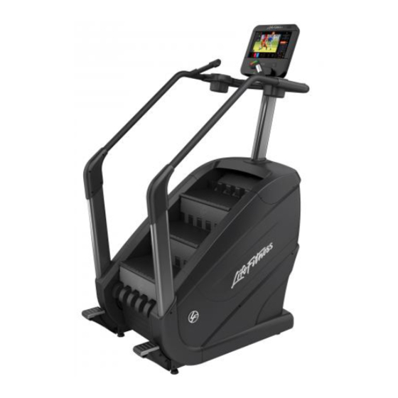
- Page 1 Life Fitness PowerMill™ Climber Assembly Instructions 95PS-XX03, 95PS-XX04 Assembly Instructions 1015938-0001 REV AA...
-
Page 3: Table Of Contents
Specifications...............21 © Copyright 2021, Life Fitness, LLC. All Rights Reserved. Life Fitness, Hammer Strength, Cybex, ICG and SCIFIT are registered trademarks of Life Fitness, LLC and its affiliated companies and subsidiaries. Brunswick and related trademarks used under license from Brunswick Corporation. -
Page 4: Getting Started
1. Getting Started Safety Instructions Read all instructions before use. CAUTION: Any changes or modifications to this equipment could void the product warranty. WARNING: To reduce the risk of burns, fire, electric shock, or injury, it is imperative to connect each product to a properly grounded electrical outlet. - Page 5 these reasons this unit is designed for use only in a controlled setting. The PowerMill Climber is not designed for use in the home and should not be used in an environment where children or animals might have access. Page 3 of 23...
-
Page 6: Consignes De Sécurité
Consignes de Sécurité Lire toutes les instructions avant usage. ATTENTION : Toute modification apportée à cet équipement pourrait en annuler la garantie. AVERTISSEMENT : Pour réduire les risques de brûlures, d’incendies, de décharges électriques ou de blessures, il est essentiel de brancher chaque appareil sur une prise électrique correctement mise à la terre. AVERTISSEMENT : Les systèmes de surveillance de la fréquence cardiaque peuvent être inexacts. - Page 7 • Si certaines étiquettes d’avertissement sont manquantes ou endommagées, contactez immédiatement le service d’assistance à la clientèle. Nous vous en fournirons de nouvelles. Les étiquettes d’avertissement sont expédiées avec les appareils et doivent être installées avant utilisation de ces derniers. Life Fitness n’est pas responsable des étiquettes manquantes ou endommagées.
-
Page 8: Electrical Power Requirements
Electrical Power Requirements The PowerMill with the Integrity and Discover consoles require an AC power supply according to the electrical configurations listed in the chart below. Console Supply Voltage Frequency Output Voltage Output Current Integrity X/ C, Integrity 100 - 240 VAC 50 - 60 Hz 24 VDC with Attachable TV,... -
Page 9: Product Overview
2. Product Overview Product Features Item Description Qty. Console Stop / Increase Speed Keypads Contact Heart Rate Sensors Cup Holder Step Assist Wheel Leg Leveler Stop / Decrease Speed Keypads Where to Place Unit Following all Safety Instructions, move the unit to the location in which it will be used. See Specifications for the dimensions of the footprint. -
Page 10: How To Stabilize Unit
How to Stabilize Unit After placing the unit in position, check the unit’s stability by attempting to rock it. Any slight rocking indicates that the unit must be leveled. There are four stabilizing feet on the unit. Check the front and back stabilizing feet to determine which foot does not rest fully on the floor. -
Page 11: Assembly
3. Assembly Hardware and Required Tools Hardware Item Description Qty. M8 X 35 mm Socket head cap screw Grommet M10 X 20 mm Hex head cap screw M8 X 16 mm Button head cap screw M8 X 18 mm Hex washer head screw M4 X 16 mm Phillips pan head screw M4 X 12 mm Phillips pan head screw M5 X 14mm Phillips pan head screw (Discover Console) -
Page 12: Remove Base From Base Pad
Remove Base from Base Pad Item Description Qty. PowerMill Base Base Pad Install Step Assists Item Description Qty. Step Assist, Left Step Assist, Right M8 X 35mm Socket Head Cap Screw 18-20 ft. lbs. (24.4-27.1 Nm) Install Left and Right Rear Uprights Item Description Qty. -
Page 13: Install Console Support Weldment
Install Console Support Weldment 1. Place top cap gasket on console support weldment. 2. Route cables up through console support weldment. 3. Secure console support weldment to base. Item Description Qty. Console Support Weldment Top Cap Gasket M8 X 18mm Hex Washer Head Screw Cables 18-20 ft. -
Page 14: Install Handlebars
Install Handlebars 1. Join the left and right rear handlebars to left and right "L" tubes (front handlebars). Secure using screws. Item Description Qty. "L" Tube (Front Handlebar), Left Handlebar (Rear), Left "L" Tube (Front Handlebar), Right Handlebar (Rear), Right M8 X 16mm Button Head Cap Screw 16 - 18 ft. -
Page 15: Install Accessory Trays
Install Accessory Trays Item Description Qty. M4 X12mm Phillips Pan Head Screw Accessory Tray, Top Right Accessory Tray, Bottom Right Accessory Tray, Top Left Accessory Tray, Bottom Left 10 -12 in. lbs. (1.1 - 1.3 Nm) Attach Handlebar Covers Item Description Qty. -
Page 16: Base To Console Cable Connections - Discover / St
Base to Console Cable Connections - Discover / ST Item Description Qty. CAT5e Ethernet 24V DC Coax, RG6, Base Ground Wire Base to Console Cable Connections - Integrity X / C Item Description Console to Base Power Base Signal Left Handlebar Keypad Switch Lifepulse Right Handlebar Keypad Switch Base to Console Cable Connections - Integrity SL... -
Page 17: Attach Discover Console (Se3/Hd/St) And Rear Console Shroud Assembly
Attach Discover Console (SE3/HD/ST) and Rear Console Shroud Assembly Use the M5 X 14 Phillips Pan Head Screws to secure both the console and rear console shroud assembly to the console support weldment. Item Description Qty. Console M5 X 14 Phillips Pan Head Screw Rear Console Shroud Assembly 14 - 16 in. -
Page 18: Tighten Hardware And Verify Leg Leveler Position
Tighten Hardware and Verify Leg Leveler Position Tighten all hardware and make sure all leg levelers are down. Item Description Qty. Leg Leveler Page 16 of 23... -
Page 19: Remove Line Cord Bracket And Secure Power Cord
Remove Line Cord Bracket and Secure Power Cord 1. Remove line cord bracket and screw. Item Description Qty. Bracket, Line Cord M4 X 12mm Phillips Pan Head Screw 2. Plug in power cord and reattach line cord bracket and screw. Item Description Qty. -
Page 20: Service And Technical Data
4. Service and Technical Data Preventive Maintenance Tips The following preventive maintenance tips will keep the product operating at peak performance: • Locate the product in a cool, dry place. • Clean the top surface of the steps regularly. • Clean the display console and all exterior surfaces with an approved or compatible cleaner (see Approved Cleaners) and a microfiber cloth. -
Page 21: Preventive Maintenance Schedule
Preventive Maintenance Schedule Item Weekly Monthly Quarterly Biannually Comments Console Overlays Clean Inspect Cup Holder Clean Inspect Console Mounting Inspect Bolts Frames Clean Inspect Plastic Covers Clean Inspect Lifepulse Sensors Clean / Inspect Leg Levelers Inspect / Adjust Side Hand Rails Clean Inspect Steps... -
Page 22: How To's
Belt Inspection - Brake and Drive Belts The PowerMill has two belts. A brake belt and a drive belt. Item Description Brake belt Drive belt Inspect belts for cracking or wear. Belt Cracking If cracks appear 2 cm or less apart, then 80% of the belt life is gone and the belt should be replaced. Belt Wear (Material Loss) If material loss is occurring as shown above, the belt should be replaced. -
Page 23: Specifications
5. Specifications Specifications Designed Use Heavy / Commercial Maximum User Weight 400 lbs. / 181 kg Ceiling Height Minimum 9 ft. / 2.7 m Usable Step Surface Area 205 sq. in. (520.7 cm) Power Requirements 100 - 240 volts, 50/60 Hz, 5 Amps Resistance Levels 26 (0-25) Heart Rate Monitoring... -
Page 24: Warranty
Who Pays Transportation and Insurance For Service If the Product or any covered part must be returned to a service facility for repairs, We, Life Fitness Family of Brands, will pay all transportation and insurance charges for the first year. You are responsible for transportation and insurance charge after the first year. -
Page 25: Effects Of State Laws
Changes in Warranty Not Authorized No one is authorized to change, modify or extend the terms of this limited warranty. Effects of State Laws This warranty gives you specific legal rights, and you may have other rights which vary from state to state and country by country.
Need help?
Do you have a question about the PowerMill 95PS-XX03 and is the answer not in the manual?
Questions and answers