Table of Contents
Advertisement
Available languages
Available languages
Quick Links
Advertisement
Table of Contents

Related Manuals for EPTA iarp City Milano Slave


Summary of Contents for EPTA iarp City Milano Slave
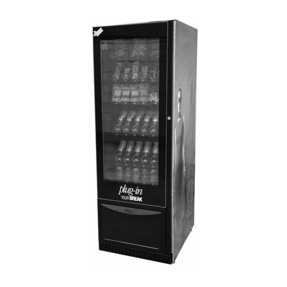
- Page 1 DISTRIBUTORE AUTOMATICO REFRIGERATED VENDING MACHINE MILANO SLAVE Cod. UM000205...
- Page 3 ITALIANO PREMESSA • Il presente manuale è parte integrante del distributore e dovrà quindi essere conservato in luogo noto, facilmente accessibile, in buone condizioni, per tutta la vita operativa della macchina (compresi gli eventuali passaggi di proprietà). Il suo fine, è la trasmissione delle informazioni necessarie all’uso competente e sicuro della macchina stessa.
-
Page 4: Unità Di Misura
NOTE DI CONSULTAZIONE COMPOSIZIONE DEL MANUALE 4.1 ELENCO SIMBOLI ATTENZIONE! - Informazioni Il presente manuale è suddiviso in sezioni • riguardanti la sicurezza dell’addetto (capitoli). al rifornimento e l’integrità della macchina e dei prodotti. NOTA - Al fine di potere agevolmente verificare ATTENZIONE! - Interventi potenzial- che le varie sezioni siano complete e che mente pericolosi per il manutentore... -
Page 5: Avvertenze Generali
AVVERTENZE GENERALI AVVERTENZE E CAUTELE DESTINAZIONE D’USO DEL • Per la manutenzione ordinaria, non utilizzare DISTRIBUTORE assolutamente, detergenti, diluenti, solventi, ecc... • Il distributore oggetto del presente manuale è stato • È tassativamente vietato collocare e/o abbando- progettato, realizzato e protetto per la distribuzione nare sul distributore, utensili e quant’altro di poten- automatica di prodotti confezionati: pasticceria, zialmente lesivo per la sicurezza delle persone e... -
Page 6: Caratteristiche Elettriche
CARATTERISTICHE GENERALI DATI DI IDENTIFICAZIONE • I dati per l’identificazione del distributore, sono riportati nell’apposita targa solidale alla struttura del distributore stesso: • Costruttore • Modello • Codice • Marcatura di conformità • Anno di fabbricazione • Tensione di alimentazione (V) •... -
Page 7: Installazione
INSTALLAZIONE DIMENSIONI D’INGOMBRO E PESI MILANO SLAVE con imballo senza imballo 1830 1950 T. 3 CARATTERISTICHE DELL’IMBALLO • L’unità viene spedita ancorata su pall et in legno protetta da montanti angolari, cappello in cartone e protetta integralmente da involucro in nylon. All’arrivo del distributore imballato, posizionarlo (in verticale) in ambiente riparato ed asciutto con superficie piana e sufficientemente robusta. - Page 8 INSTALLAZIONE CARATTERISTICHE DEL LOCALE • Il distributore va installato in locale asciutto e riparato con temperatura ambientale: 10°C ÷ 43°C e umidità massima: 90%. • Verificare in via preventiva che la portata della pavimentazione sia abbondantemente adeguata a sostenere il peso dichiarato. •...
- Page 9 INSTALLAZIONE FISSAGGIO A PARETE (operazione facoltativa) NOTA - L’operazione di predisposizione del distributore per il suo ancoraggio a parete, va eseguita prima del piazzamento e del relativo livellamento. • Montare le due staffe, nella parte posteriore del distributore. • Posizionare e livellare il distributore, quindi fissarlo alla parete, mediante due tasselli ad espansione (staffe, viti e tasselli, non sono forniti).
- Page 10 INSTALLAZIONE SERRAGGIO DADI SERRATURA ISTRUZIONI PER SERRAGGIO A MANO DEL DADO TRIANGOLARE SU SERRATURE A LEVETTA. • Dado triangolare (fig.5). F. 5 • Installare con chiave d’uso inserita (fig.6). F. 6 • Inserire la levetta (A), la rosetta anti-svitamento (B) e il dado (C) (fig.7), ruotandolo manualmente (fig.8).
- Page 11 INSTALLAZIONE SERRATURE RI-PROGRAMMABILI Prima di installare la serratura e serrare i dadi assicurarsi che sia stata già programmata. La serratura è sicuramente programmata se è in grado di inserire ed estrarre la chiave di uso (colore argento). PROGRAMMAZIONE • Inserire la chiave di programmazione (colore oro) •...
- Page 12 INSTALLAZIONE 10. COLLEGAMENTO ALLA RETE ELETTRICA • Il distributore è dotato di un cavo di alimentazione che deve essere inserito nella presa predisposta sul pannello posteriore. NOTA - È cura del Manutentore Tecnico, responsabile dell’installazione del distributore, accertarsi che l’impianto di alimentazione elettrica sia rispondente alle vigenti norme di sicurezza. In caso di dubbi, non procedere all’installazione e richiedere un controllo accurato dell’impianto da parte di personale qualificato ed abilitato a svolgere queste mansioni.
- Page 13 PREDISPOSIZIONE DEL DISTRIBUTORE IMPOSTAZIONE CASSETTI • Il distributore viene fornito con n° tre cassetti. 1.1 COMPOSIZIONE CASSETTI Spirali destre (rotazione in senso orario) Separatori Listello porta etichette Supporto ponte F. 15 F. 16 NOTA - Le spirali sono azionate da motori elettrici montati assialmente che determinano la rotazione delle spirali singole e doppie, in modo contrapposto.
- Page 14 PREDISPOSIZIONE DEL DISTRIBUTORE 1.2 CONNETTORI CASSETTI • Ogni cassetto è provvisto di un connettore (A) preposto a trasmettere i dati selezionati per il cassetto stesso. F. 17 • I connettori (A) si trovano in fondo a destra dei cassetti F.17 NOTA - Questa operazione si rende necessaria anche per rimuovere e/o sostituire un cassetto.
- Page 15 PREDISPOSIZIONE DEL DISTRIBUTORE INSERIMENTO TARGHETTE • Estrarre parzialmente il cassetto nel quale si deve inserire la targhetta. • Sul fronte del cassetto è presente un profilo preposto a ricevere le targhette indicanti il codice del prodotto selezionabile ed il prezzo ad esso attribuito. F.
- Page 16 PREDISPOSIZIONE DEL DISTRIBUTORE REGOLAZIONE DELLE SPIRALI Le spirali possono essere regolate per meglio erogare le diverse tipologie dei prodotti selezionabili. Per effettuare questa regolazione occorre: • Tirare la spirale fino a liberare l’innesto dalla sede del motore. • Ruotare la spirale di 45° per volta, fino a trovare la posizione 45°...
- Page 17 PREDISPOSIZIONE DEL DISTRIBUTORE SOSTITUZIONE DEI MOTORI La procedura è la seguente: • Estrarre il cassetto dal distributore ed appoggiarlo su piano di lavoro. • Estrarre il motore e la spirale dal cassetto. • Estrarre la spirale. • Estrarre i connettori elettrici. •...
- Page 18 PREDISPOSIZIONE DEL DISTRIBUTORE • Montare la spirale destra e la spirale sinistra. • Predisporre la spirale doppia sulla corsia di destinazione. • Inserire il cassetto nel distributore ed eseguire la regolazione delle spirali come da indicazioni riportate al punto 2. F.
- Page 19 IMPIEGO OPERATIVO RIFORNIMENTO CASSETTI Note generali per il buon funzionamento • Verificare il buon scorrimento dei prodotti. • Evitare se possibile di affiancare sacchetti i cui lembi possano intralciarsi durante lo scorrimento. • Caricare i coni nel cassetto più basso . •...
- Page 20 IMPIEGO OPERATIVO 2. ACCENSIONE DEL DISTRIBUTORE Dopo aver chiuso la portella principale, collegare la spina del cavo di alimentazione, alla rete elettrica. A questo punto sul display viene visualizzato il messaggio e si attiva l’autoconfigurazio-ne che controlla tutte le impostazioni precedentemente definite: •...
-
Page 21: Manutenzione Straordinaria
Ogni intervento è di stretta competenza di personale specializzato. NOTA - La Ditta EPTA si esime da qualsiasi responsabilità per danni di ogni natura, generati da inadeguata manutenzione, nonché dall’impiego di parti di ricambio non originali, o non compatibili con lo standard di qualità... -
Page 22: Collegamento Master - Slave
MANUTENZIONE COLLEGAMENTO MASTER - SLAVE Appoggiare sulla parte posteriore del mobile della macchina MASTER il foglio (A) (fig.32) che • troverete all’interno della macchina SLAVE, nel quale vi verrà indicato il punto dove creare un foro. F.32 • Creare un foro diametro 29mm (fig.33) e inserire l’anello passa cavo che troverete all’interno della macchina SLAVE (fig.34);... - Page 23 MANUTENZIONE • Fascettare a ramo di cavi già esistente il cavo nero (B) (fig.36). F.36 • Reinserire la copertura scheda slave e chiudere la colonna comandi, vedere manuale programmazione per menu macchina MASTER. • I Numeri iniziali identificativi per la selezione saranno 1 per la macchina master e 2 per la macchina slave.
- Page 26 ENGLISH PREMISE • The present manual is an integral part of the machine itself, therefore it will have to be kept in a wellknown place, easily accessible, in good state, for the whole operative life of the machine (included transfer of titles, if any). Its aim is the divulgation of the necessary information to the qualified and safe use of the machine itself.
-
Page 27: List Of Symbols
REFERENCE NOTES 4.1 LIST OF SYMBOLS COMPOSITION OF THE MANUAL WARNING! - Information concerning • This manual is subdivided into sections (chapters). the safety of the person in charge of the supply, and the integrity of the NOTE - In order to check easily that the various machine. -
Page 28: Technical Maintenance
GENERAL WARNINGS WARNING AND CAUTIONS DESTINATION OF USE OF THE • For the routine maintenance, do not assolutely use, MACHINE detergents, diluents, solvents, etc... • The dispenser described herein is designed • It is absolutely forbidden to place and/or abandon and manufactured for automatic distribution of on the machine, tools or any other thing which might packaged products: sweets, snacks, chips, cans,... -
Page 29: Electrical Characteristics
GENERAL SPECIFICATION IDENTIFICATION DATA • The plate bearing the vending machine identification data and the main electro/mechanical characteristics, is fixed to the body of the vending machine itself. • Manufacturer • Model • Code • Marks of compliance • Year of construction •... -
Page 30: Installation
INSTALLATION DIMENSIONS AND WEIGHTS MILANO SLAVE packed unpacked 1830 1950 T. 3 PACKING SPECIFICATIONS • The unit is shipped anchored on wooden pallets, with angular plates, carton cover and compeletely wrapped with nylon. At the arrival of the packed vending machine it is advisable to place it in vertical position, in a sheltered and dry place with a plane and strong surface. - Page 31 INSTALLATION INSTALLATION PLACE CHARACTERISTICS • The vending machine has to be installed in a dry and sheltered place, with a temperature of 10°C ÷ 43°C and a maximum humidity of: 90%. • Be sure in advance that the floor carrying capacity is adequate to the declared weight. •...
- Page 32 INSTALLATION WALL INSTALLATION (OPTIONAL OPERATION) NOTE - The operations to prepare the dispenser for wall fixing is to be carried out before positioning and levelling the dispenser. • Prepare the two special fixing brackets in the back side of the vending machine. •...
- Page 33 INSTALLATION CLAMPING THE LOCK NUTS INSTRUCTIONS FOR HAND-TIGHTENING OF THE NEW TRIANGULAR NUT ON CAM LOCKS. • Triangular nut (fig.5). F. 5 • Install with user key inserted (fig.6). F. 6 • Insert the cam (A), external tab lock washer (B) and the nut (C) (fig.7), rotate the triangular nut manually (fig.8).
- Page 34 INSTALLATION RE-PROGRAMMABLE LOCKS Before installing the lock and tightening the nuts make sure that the lock has already been programmed. The lock is definitely programmed if it can enable inserting and removing the key from use (silver colour). PROGRAMMING • Insert the programming key (gold colour) •...
- Page 35 INSTALLATION 10. ELECTRIC CONNECTION The vending machine is supplied with a power cord to be plugged into the socket provided in the • back side. The Maintenance Technician is responsible for your vending machine installation and WARNING - will therefore have to make sure that the power supply system is in compliance with the safety regulations in force.
-
Page 36: Tray Configuration
PREDISPOSITIONS OF THE MACHINE TRAY ARRANGEMEENT • The standard vending machine is supplied with 3 trays. 1.1 TRAY CONFIGURATION Right spirals (clockwise) Separators Label strip Sliding guide F. 15 F. 16 WARNING Spirals are driven by axially mounted electric motors which rotate single and double spirals in opposed directions. - Page 37 PREDISPOSITIONS OF THE MACHINE TRAYS CONNECTORS • Each tray includes a connector (A) for transmission of data selected for such tray. F. 17 • The connectors (A) are located on the right side of the trays (F.17) NOTE - This operation is required as well to remove and/or replace a tray. Some products require more space in height and it may be necessary to “forgo”...
-
Page 38: Label Application
PREDISPOSITIONS OF THE MACHINE LABEL APPLICATION • Partially remove the tray where the tag is to be inserted. • On the tray front, a suitable strip is provided for receiving the labels that indicate the product code to select and the corresponding product price. - Page 39 PREDISPOSITIONS OF THE MACHINE SPIRALS ADJUSTMENT The spirals can be adjusted to obtain better dispensing of the product selections. Proceed in the following way to adjust the spirals: • Pull the spiral until releasing its coupling from the motor seat; •...
- Page 40 PREDISPOSITIONS OF THE MACHINE MOTORS REPLACEMENT Follow these instructions: • remove the tray from the vending machine and place it on your work top • remove the tray spiral and motor • remove the spiral. • remove the electric connectors. •...
- Page 41 PREDISPOSITIONS OF THE MACHINE • Mount the right-hand spiral and the left-hand spiral. • Mount the double spiral in the corresponding lane . • Replace the tray into the vending machine and adjust the spirals according to the instructions provided in section 2. F.
- Page 42 OPERATING USE TRAYS SUPPLY General tips for good operation • Make sure that the products are free to move. • If possible, do not place bags side by side if their ends could become entangled during feeding. • Supply cones to the bottom tray.
- Page 43 OPERATING USE 2. POWER-ON After closing the door, plug the vending machine into the mains socket . The machine display will then read this message: “SELF-DIAGNOSIS – PLEASE WAIT”. Self-configuration will start and all the earlier settings will be checked: •...
-
Page 44: Nonscheduled Maintenance
MAINTENANCE CLEANING To guarantee smooth vending machine operation, cleaning operations should be carried out regularly. Daily • Use a damp cloth or food contact-approved detergents to clean the showcase , the product dispensing tray , the control panel (keypad, display, etc.), the “operating instructions” label case . •... -
Page 45: Master - Slave Connection
MAINTENANCE MASTER - SLAVE CONNECTION • Put the drawing (A) to the rear side of master machine (fig.32), on the drawing you will be shown the point where you create a hole. F.32 • Create the hole Ø29mm (fig.33) and insert the cable ring (fig.34); pass the black wire con- nection (B). - Page 46 MAINTENANCE • Fix the black wire (B) by the fasteners (fig.41). F.36 • Replace the slave board cover and close the control column, see manual programming menu MASTER machine. • The initial identification numbers for selection will be 1 for the master machine and 2 for the slave machine.
Need help?
Do you have a question about the iarp City Milano Slave and is the answer not in the manual?
Questions and answers