Table of Contents
Advertisement
SYLVAC SA – Chemin du Closalet 16 – CH-1023 Crissier
Tel. 0041 (0)21 637 67 57 – Fax 0041 (0)21 637 67 40
E-mail : service@sylvac.ch -
Printed in Switzerland – Changes without prior notice
SYLVAC-Scan 25
SYLVAC-Scan 50
SYLVAC-Scan 50 CE Plus
SYLVAC-Scan 50 Plus
User's manual
www.sylvac.ch
1 - 36
681.101.05-120
Advertisement
Table of Contents

Subscribe to Our Youtube Channel
Related Manuals for Sylvac Scan Series


Summary of Contents for Sylvac Scan Series
- Page 1 SYLVAC-Scan 50 SYLVAC-Scan 50 CE Plus SYLVAC-Scan 50 Plus User’s manual SYLVAC SA – Chemin du Closalet 16 – CH-1023 Crissier Tel. 0041 (0)21 637 67 57 – Fax 0041 (0)21 637 67 40 E-mail : service@sylvac.ch - www.sylvac.ch Printed in Switzerland – Changes without prior notice 681.101.05-120...
-
Page 2: Table Of Contents
System Description Specification SYLVAC-Scan 25 Specification SYLVAC-Scan 50 Specification SYLVAC-Scan 50 Plus Specification SYLVAC-Scan 50C plus Installation Visual Inspection Lifting SYLVAC-Scan 25 Lifting SYLVAC-Scan 50 and 50 Plus Installing The System Electrical Connections Workholding General Headstock Tailstock Tooling Operation - Quick Guide... - Page 3 Limit Switches and Linear Scale Reader Calibration values of 'daily setting piece Trouble Shooting Troubleshooting Start-Up Problems Error Messages 6.3.1 Pro-Measure Error Messages 6.3.2 Pro-Composer General Error Messages 6.3.3 Pro-Composer Defining Measurements Error Messages 6.3.4 Pro-Composer Import DXF Error Messages EC Conformity declaration ISO/CEI guide 22 + EN4504 Guarantee...
-
Page 4: Introduction
Introduction Introduction The SYLVAC Scan range of non-contact measuring systems from SYLVAC SA is based on proven technology used in many standard and special purpose measuring systems. The machine is controlled using Pro-Measure and Pro-Composer Software running under the Windows 7 Professional. -
Page 5: Use In Accordance With Intended Usage
1.2.5 Use in accordance with intended usage The SYLVAC-Scan machine is intended solely for contactless measurement. Any other use or a use outside the intended use is considered as non-conforming. The SYLVAC SA Company does not accept any responsibility for damage that could result from this. Use in accordance with intended usage also includes ... -
Page 6: Control Of The System
Do not undertake any conversion or apply any addition of modification to the machine without the authorisation of the SYLVAC SA company. All conversion measures require written confirmation from the SYLVAC SA company Immediately replace parts of the machine that are not in impeccable condition. -
Page 7: Cleaning The Machine And Waste Disposal
1.2.16 Cleaning the machine and waste disposal Handle and dispose of the materials and substances used properly, in particular • During work on lubrication systems and equipment. • During cleaning with solvents 1.2.17 Machine noise The noise level LpA emitted by the machine is less than 70 dB(A). 7 - 36... -
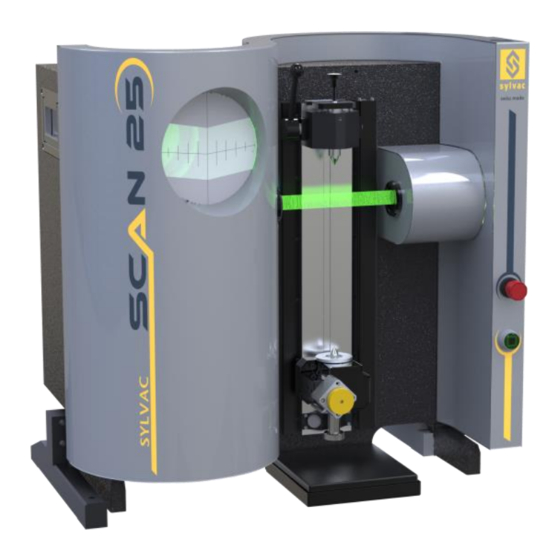
Page 8: System Description
A stepper motor allows automatic component rotation for dynamic measurements (run-out, for example). SYLVAC-Scan 50 Plus offers in addition a motorized axis used to incline the workpiece to the helix angle of the thread (Slew). Measurements can be made directly by positioning the feature(s) to be measured at the measuring point in the fixture. - Page 9 A special feature of this system is the projector screen which provides a five times magnified (nominal) image of the component for SYLVAC-Scan 25 (x4 nominal for SYLVAC-Scan 50 and 50 Plus) and an exact indication of the measurement point. The screen is used for component positioning during direct measurement and can be used in programming as well as providing a visual check on component alignment, focus and cleanliness.
- Page 10 SYLVAC-Scan 25 specifications Metric Imperial DIMENSIONS Measuring center (HxWxD) 840x640x460 mm 33x25x18 in Computer mini tower WEIGHT Measuring center 55Kg 121 lbs Complete System including PC 85Kg 187 lbs OPERATIONAL REQUIREMENTS Storage Temp. Range -30 to 60°C -22 to 140°F Storage Humidity 75% rh max.
- Page 11 SYLVAC-Scan 50 specifications Metric Imperial DIMENSIONS Measuring center (HxWxD) 1050 x 800 x 580 mm 41 x 32 x 23 in Computer mini tower WEIGHT Measuring center 115 Kg 250 lbs Complete System including PC 130 Kg 283 lbs OPERATIONAL REQUIREMENTS Storage Temp.
-
Page 12: Specification Sylvac-Scan 50 Plus
SYLVAC-Scan 50 Plus specifications Metric Imperial DIMENSIONS Measuring center (HxWxD) 1300 x 800 x 580 mm 51 x 32 x 23 in Computer mini tower WEIGHT Measuring center 160 Kg 350 lbs Complete System including PC 175 Kg 383 lbs OPERATIONAL REQUIREMENTS Storage Temp. -
Page 13: Specification Sylvac-Scan 50C Plus
SYLVAC-Scan 50CE Plus specifications Metric Imperial DIMENSIONS Measuring center (HxWxD) 1050 x 800 x 580 mm 41 x 32 x 23 in Computer mini tower WEIGHT Measuring center 125 Kg 272 lbs Complete System including PC 140 Kg 320 lbs OPERATIONAL REQUIREMENTS Storage Temp. -
Page 14: Installation
Configuration Panel and Local Language options in the Windows menu Check all items against the packing list, and report any shortages immediately to SYLVAC SA. If the gauging system is to be stored for a period before installation, ensure that it is carefully repacked or otherwise protected, and store it only indoors avoiding high humidity (>75%) or extreme temperatures... -
Page 15: Lifting Sylvac-Scan 50 And 50 Plus
Warning: Check the voltage setting on the computer, SCREEN and printer before connecting the mains electrical supply. Warning: Do NOT attempt to alter the voltage setting on the computer. Contact SYLVAC SA if the label voltage does not match your electrical supply. - Page 16 System Connections, SYLVAC-Scan 25, 50 and 50 Plus Power Lead (to mains supply) Printer Cable RS232 (Motor Comms. cable) VGA Cable (Monitor) USB cable Machine ID Plate Keyboard Cable Machine On/Off Switch Mouse Cable 16 - 36...
-
Page 17: Workholding
The tooling for the gauging system, is industry standard Morse Taper 1 tooling for SYLVAC-Scan 25 (Morse 2 for SYLVAC-Scan 50 and 50 Plus) which locates in receiving tapers in the headstock and tailstock. To insert the tooling use only a gentle movement until the taper locks. If the taper will not lock, check the cleanliness of both the tool and the headstock and tailstock, ensuring that the tooling release screws are retracted. -
Page 18: Operation - Quick Guide
Pro-Composer or manually using the Pro-Measure Procal editor. Long term accuracy of the SYLVAC Scan is assured through the use of a setting master, provided with every system, to calibrate the system at start-up. The setting master is stored with the gauge, the location of which will vary depending on gauge type. -
Page 19: Start-Up
Ensure that all electrical connections are made and that there is no CD in the CD-Rom drive (if present). Switch on power to the SYLVAC-Scan with the main switch at the rear of the gauge. Switch on power to the computer. -
Page 20: Calibrate A Profile Gauge
Check that the serial number on the setting master corresponds to that displayed on the computer SCREEN, clean the setting master and re-run the calibration program. If the problem recurs, contact the SYLVAC SA Service organization. Measurement Mode In Measurement mode the measurement system will support the following functions : ... -
Page 21: Start A Measurement Program
Start a Measurement program 9. Select the 'Open Measurement' option from the 'File' menu. 10. Select the file you wish to open from the file selector. 11. Press the 'OK' button. 12. Your file will now be opened. 13. Once the file has finished loading and the toolbar buttons become active (colored), press the 'F2' button to start the program running. -
Page 22: Maintenance
The system shall be recalibrated using a complete set of diameter and length standards. It is recommended that machines situated on shop floors are calibrated to SYLVAC specifications twice a year. Machines situated in controlled environments such as temperature controlled inspection rooms can be calibrated once a year. -
Page 23: Mechanical Sylvac-Scan 50 And 50 Plus
Mechanical SYLVAC-Scan 50 and 50 Plus Tailstock If the tailstock becomes too loose to remain in position, the clamping mechanism must be adjusted. Remove the tailstock from the machine by raising it to the top of the slide and lifting it forwards, out of the tenon slot. -
Page 24: Led
The lifespan of the LED is 8x higher, which means no need to change the LED very often.The approved SYLVAC technician will replace the LED when conducting a maintenance service. It will be necessary to recalibrate the measuring system. Limit Switches and Linear Scale Reader Limit switches and a linear scale reader (encoder) detect the position of slide. -
Page 25: Specification Sylvac-Scan
Trouble Shooting Trouble Shooting SYLVAC Scan gauging systems have been designed for ease of use and trouble-free operation. This section details problems that might occur at start-up and also a list of error messages which can be reported by the system when running. -
Page 26: Error Messages
Error Messages Error messages are displayed in a window in the center of the screen display. If an error message is displayed while a part program is being run, the program will usually be halted. 6.3.1 Pro-Measure Error Messages Attempt to move beyond maximum limit. A motor move command has attempted to drive the motor past its maximum travel. - Page 27 END:SUB without BEGIN:SUB. An End:Sub keyword has been found outside of a subroutine definition. Expression : Division by zero. An attempt has been made to divide a number by zero. Check the logic of the expression. Expression : Invalid variable. A variable has been used with the wrong number of indexes.
- Page 28 Invalid keyword. The Procal keyword has not been recognised, either the word has been incorrectly typed, or a required Plugin is not present or has not initialised correctly. Invalid parameter. An incorrect parameter type has been passed. Check the syntax of the word in question. Left hand bracket missing.
- Page 29 Segment name already included. The specified Procal segment has been included in the program more than once. Segment name not found. The specified Procal segment could not be found. Serial port portnumber is either in use or does not exist. An attempt has been made to open a serial port which is either in use by another application or does not exists on the computer.
-
Page 30: Pro-Composer General Error Messages
6.3.2 Pro-Composer General Error Messages System is not calibrated. A successful calibration is required before scanning. In order to perform a component scan, the system must be calibrated. This is done using the Open Calibration command of the Pro-Measure software. filename Schematic contains non registered Feature Types. -
Page 31: Pro-Composer Defining Measurements Error Messages
6.3.3 Pro-Composer Defining Measurements Error Messages Measurement Zone(s) not suitable for Feature Type. The zone doesn't contain the specified feature, or if it is a two zone intersection, the zones don't cause an intersect point. Standards Database Error. Insufficient Data. A standard has been chosen, but not all the fields have been selected (turned green) on the Standards Database page or the Measurement Properties dialog box.. -
Page 32: Pro-Composer Import Dxf Error Messages
6.3.4 Pro-Composer Import DXF Error Messages Failed to find link name in DXF file. Correct problem in CAD application and retry. Problem with the profile layer. The profile must be a fully connected outline. Unrecognized DXF entity or corrupt filename file. Correct problem in CAD application and retry. -
Page 33: Ec Conformity Declaration
The periodic check-ups, the adjustments or the maintenance Sylvac SA owns all parts removed from repaired products. If Sylvac SA repairs or replaces a part of a product, its warranty term is not extended. In case of replacement the new component has a warranty of 1 year, without effect on the initial warranty period. -
Page 34: Notes
Notes 34 - 36... - Page 35 Notes 35 - 36...
- Page 36 Changes without prior notice Sous réserve de toute modification Änderungen vorbehalten 2015.09 – 681.101.05-120 Edition : 36 - 36...
Need help?
Do you have a question about the Scan Series and is the answer not in the manual?
Questions and answers