Table of Contents
Advertisement
Quick Links
Advertisement
Table of Contents

Subscribe to Our Youtube Channel
Related Manuals for SIGLENT TECHNOLOGIES SDS5000X Series


Summary of Contents for SIGLENT TECHNOLOGIES SDS5000X Series
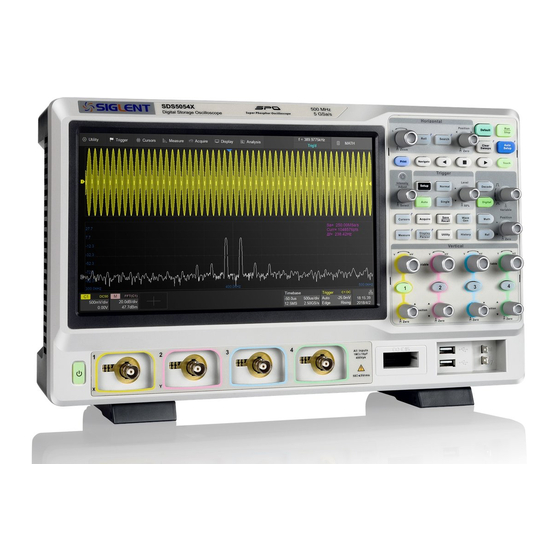
- Page 1 SDS5000X Series Digital Oscilloscope User Manual UM0105X-E01E...
-
Page 3: Table Of Contents
SDS5000X Series Digital Oscilloscope User Manual Contents CONTENTS .............................. 1 INTRODUCTION ..........................8 IMPORTANT SAFETY INFORMATION .................... 9 ..........................9 ENERAL AFETY UMMARY ........................11 AFETY ERMS AND YMBOLS ..........................12 ORKING NVIRONMENT ..........................14 OOLING EQUIREMENTS ....................14 OWER AND ROUNDING EQUIREMENTS .................................16 LEANING ..........................16... - Page 4 SDS5000X Series Digital Oscilloscope User Manual ...........................38 7.3.3 USB Peripherals ............................38 7.3.4 External Monitor .............................39 7.3.5 Auxiliary Output .......................39 7.3.6 SAG1021I Waveform Generator ..............................39 7.3.7 Probes ............................40 7.3.8 Logic Probe TOUCH SCREEN DISPLAY ......................41 ................................41 VERVIEW ................................42 ...............................43 ...........................45 HANNEL ESCRIPTOR ....................47...
- Page 5 SDS5000X Series Digital Oscilloscope User Manual HORIZONTAL AND ACQUISITION SETUP ................80 14.1 T .............................80 IMEBASE ETUP 14.2 A ............................81 CQUISITION ETUP ..............................81 14.2.1 Overview ..............................83 14.2.2 Acquisition ...............................87 14.2.3 Roll Mode ...............................87 14.2.4 Sequence 14.3 H ................................91 ISTORY 14.4 Z ................................94...
- Page 6 SDS5000X Series Digital Oscilloscope User Manual ..........................149 16.3.3 SPI Serial Decode 16.4 UART T ....................... 150 RIGGER AND ERIAL ECODE ........................150 16.4.1 UART Signal Settings ............................. 151 16.4.2 UART Trigger ........................152 16.4.3 UART Serial Decode 16.5 CAN T ......................
- Page 7 SDS5000X Series Digital Oscilloscope User Manual ........................202 18.3.2 Horizontal Measurement ......................204 18.3.3 Miscellaneous Measurements .......................... 205 18.3.4 Delay Measurement 18.4 T ................................207 REND 18.5 D .............................. 208 ISPLAY 18.6 M ......................... 209 EASUREMENT TATISTICS 18.7 S ..........................211...
- Page 8 SDS5000X Series Digital Oscilloscope User Manual 25.1 O ..............................266 VERVIEW 25.2 M ................................267 HISTOGRAM ..........................270 26.1 O ..............................270 VERVIEW 26.2 R ............................273 EGION ETTING POWER ANALYSIS........................275 27.1 O ..............................275 VERVIEW 27.2 P ............................276...
- Page 9 SDS5000X Series Digital Oscilloscope User Manual 32.2 S ................................336 OUND 32.3 U ........................... 337 PGRADE OFTWARE 32.4 L ..............................339 ANGUAGE 32.5 S ............................. 339 CREEN AVER 32.6 I/O S ..............................340 ETTING ............................... 340 32.6.1 ............................341 32.6.2 Clock Source ............................
-
Page 10: Introduction
SDS5000X Series Digital Oscilloscope User Manual Introduction This user manual includes important safety and installation information related to the SDS5000X series oscilloscopes and includes simple tutorials for basic operation of the oscilloscope. The series includes the following models: Model Analogy... -
Page 11: Important Safety Information
SDS5000X Series Digital Oscilloscope User Manual Important Safety Information This manual contains information and warnings that must be followed by the user for safe operation and to keep the product in a safe condition. 2.1 General Safety Summary Carefully read the following safety precautions to avoid person injury and prevent damage to the instrument and any products connected to it. - Page 12 SDS5000X Series Digital Oscilloscope User Manual signal wire to a high voltage. Do not touch the exposed contacts or components. Look over All Terminals’ Ratings. To avoid fire or electric shock, please look over all ratings and sign instruction of the instrument. Before connecting the instrument, please read the manual carefully to gain more information about the ratings.
-
Page 13: Safety Terms And Symbols
SDS5000X Series Digital Oscilloscope User Manual Not to use the equipment for measurements on mains circuits, not to use the equipment for measurements on voltage exceed the voltage range describe in the manual. The maximum additional transient voltage cannot exceed 1300V. -
Page 14: Working Environment
SDS5000X Series Digital Oscilloscope User Manual This symbol shows that the switch is an On/Standby switch. When it is pressed, the scope’s state switches between Operation and Standby. This switch does not disconnect the device's power supply. To completely power off the scope, the power cord must be unplugged from the AC socket after the oscilloscope is in the standby state. - Page 15 SDS5000X Series Digital Oscilloscope User Manual Humidity Operating: 85% RH, 40 ℃, 24 hours Non-operating: 85% RH, 65 ℃, 24 hours Altitude Operating: ≤ 3,000 m Non-operating: ≤ 15,266 m Installation (overvoltage) Category This product is powered by mains conforming to installation (overvoltage) Category II.
-
Page 16: Cooling Requirements
SDS5000X Series Digital Oscilloscope User Manual condensation is expected. IP Rating IP20 (as defined in IEC 60529). 2.4 Cooling Requirements This instrument relies on the forced air cooling with internal fans and ventilation openings. Care must be taken to avoid restricting the airflow around the apertures (fan holes) at each side of the scope. - Page 17 SDS5000X Series Digital Oscilloscope User Manual Depending on the type and number of options and accessories (probes, PC port plug-in, etc.), the instrument can consume up to 100 W of power. Note: The instrument automatically adapts to the AC line input within the...
-
Page 18: Cleaning
SDS5000X Series Digital Oscilloscope User Manual The power cord should be unplugged from the AC outlet if the scope is not to be used for an extended period of time. CAUTION: The outer shells of the front panel terminals (CH1, CH2, CH3, CH4, EXT) are connected to the instrument’s chassis and... -
Page 19: Safety Compliance
SDS5000X Series Digital Oscilloscope User Manual labels. Warning: Any use of the scope in a manner not specified by the manufacturer may impair the instrument’s safety protection. This instrument should not be directly connected to human subjects or used for patient monitoring. -
Page 20: Informations Essentielles Sur La Sécurité
SDS5000X Series Digital Oscilloscope User Manual Informations essentielles sur la sécurité Ce manuel contient des informations et des avertissements que les utilisateurs doivent suivre pour assurer la sé curité des opé rations et maintenir les produits en sé curité . - Page 21 SDS5000X Series Digital Oscilloscope User Manual Le potentiel de la ligne de signaux est é gal à la terre, de sorte que la ligne de signaux ne doit pas ê tre connecté e à une haute tension.Ne touche pas les contacts ou les composants nus.
-
Page 22: Termes Et Symboles De Sécurité
SDS5000X Series Digital Oscilloscope User Manual Le Circuit d 'alimentation é lectrique ne peut pas ê tre mesuré à l' aide du dispositif, ni la tension qui dépasse la plage de tension décrite dans le pré sent manuel. Seuls les ensembles de sondes conformes aux spécifications du fabricant peuvent ê... -
Page 23: Environnement De Travail
SDS5000X Series Digital Oscilloscope User Manual Ce symbole avertit d'un risque potentiel de choc é lectrique. Ce symbole est utilisé pour dé signer la connexion de terre de mesure. Ce symbole est utilisé pour indiquer une connexion à la terre de sé... - Page 24 SDS5000X Series Digital Oscilloscope User Manual En fonctionnement: 0 ℃ à +40 ℃ Hors fonctionnement: -20 ℃ à +60 ℃ Note: pour évaluer la tempé rature de l'environnement, il convient de tenir compte des rayonnements solaires directs, des radiateurs thermiques et d'autres sources de chaleur.
-
Page 25: Exigences De Refroidissement
SDS5000X Series Digital Oscilloscope User Manual La caté gorie II d'installation (surtension) dé signe le niveau local de distribution d 'é nergie d' un é quipement conç u pour accé der à un circuit alternatif (alimentation alternative). Degré de pollution Un oscilloscope peut ê... -
Page 26: Connexions D'alimentation Et De Terre
SDS5000X Series Digital Oscilloscope User Manual ATTENTION: Ne laissez aucun corps é tranger pé né trer dans la lunette par les trous de ventilation, etc. Connexions d'alimentation et de terre L'instrument fonctionne avec une alimentation CA monophasée de 100 à 240 Vrms (+/- 10%) à... -
Page 27: Nettoyage
SDS5000X Series Digital Oscilloscope User Manual uniquement le cordon d'alimentation spé cifié pour cet instrument et certifié pour le pays d'utilisation. Avertissement: risque de choc é lectrique! Toute interruption du conducteur de terre de protection à l'inté rieur ou à... -
Page 28: Conditions Anormales
SDS5000X Series Digital Oscilloscope User Manual Avertissement: risque de choc é lectrique! Aucune piè ce ré parable par l'opérateur à l'inté rieur. Ne retirez pas les capots. Confiez l'entretien à un personnel qualifié Conditions anormales Utilisez l'instrument uniquement aux fins spé cifié es par le fabricant. - Page 29 SDS5000X Series Digital Oscilloscope User Manual ■ UL 61010-1:2012/R:2018-11. Prescriptions en matiè re de sé curité pour les appareils é lectriques utilisé s en laboratoire et de mesure - partie 1: prescriptions gé né rales. ■ UL 61010-2-030:2018. Prescriptions de sé curité pour les appareils é...
-
Page 30: First Steps
SDS5000X Series Digital Oscilloscope User Manual First steps 3.1 Delivery Checklist First, verify that all items listed on the packing list have been delivered. If you note any omissions or damage, please contact your nearest SIGLENT customer service center or distributor as soon as possible. If you fail to contact us immediately in case of omission or damage, we will not be responsible for replacement. -
Page 31: Maintenance Agreement
SDS5000X Series Digital Oscilloscope User Manual have a 90-day warranty. The oscilloscope's firmware has been thoroughly tested and is presumed to be functional. Nevertheless, it is supplied without warranty of any kind covering detailed performance. Products not made by SIGLENT are covered solely by the warranty of the original equipment manufacturer. -
Page 32: Document Conventions
SDS5000X Series Digital Oscilloscope User Manual Document Conventions For convenience, text surrounded by a box border is used to represent the button of the front panel. For example, Print represents the "Print" button on the front panel. Italicsizedtext with shading is used to represent the touchable or clickable menu/button/region on the touch screen.For example, DISPLAY... -
Page 33: Getting Started
SDS5000X Series Digital Oscilloscope User Manual Getting Started 5.1 Power on SDS5000X provides two ways for power on, which are: Power on Line When the “Power on Line” option is enabled, once the oscilloscope is connected to the AC power supply through the power cord, the oscilloscope boots automatically. -
Page 34: System Status
SDS5000X Series Digital Oscilloscope User Manual power supply. The only way to fully power down the instrument is to unplug the AC power cord from the outlet. The power cord should be unplugged from the AC outlet if the scope is not to be used for an extended period of time. -
Page 35: Probe
SDS5000X Series Digital Oscilloscope User Manual Probe Please visit the website at www.siglent.com for technical data and ordering information. Probe Compensation When a passive probe is used for the first time, you should compensate it to match the input channel of the oscilloscope. Non-compensated or poorly compensated probe may increase measurement inaccuracy or error. - Page 36 SDS5000X Series Digital Oscilloscope User Manual Under Perfectly Over Compensated Compensated Compensated 5. Use a non-metallic driver to adjust the low-frequency compensation adjustment hole on the probe until the waveform displayed is as the “Perfectly compensated” in the figure above.
-
Page 37: Quick Start
SDS5000X Series Digital Oscilloscope User Manual Quick Start 7.1 Front Panel Overview A. Touch Screen Display: The display and major functions area. See "Touch Screen Display" chapter for more details. B. Front Panel: Includes knobs and buttons. See "Front Panel" chapter for more details. -
Page 38: Rear Panel Overview
SDS5000X Series Digital Oscilloscope User Manual G. Power Switch H. Supporting Legs: Adjust the supporting legs properly to use them as stands to tilt the oscilloscope for stable positioning of the oscilloscope. 7.2 Rear Panel Overview A. Auxiliary Out: Outputs the trigger indicator. When Pass / Fail is enabled, outputs the pass / fail signal. - Page 39 SDS5000X Series Digital Oscilloscope User Manual F. USB Ports: One USB device to connect with a PC for remote control and one USB host to connect with a USB storage device or USB mouse / keyboard. G. AC Power Input H.
-
Page 40: Connecting To External Devices/Systems
SDS5000X Series Digital Oscilloscope User Manual 7.3 Connecting to External Devices/Systems 7.3.1 Power Supply The standard power supply for the instrument is 100~240 V, 50/60 Hz or 100~120 V, 400 Hz. Please use the power cord provided with the instrument to connect it to AC power. -
Page 41: Auxiliary Output
Press the WaveGen button on the front panel or touch the screen Utility AWG Menu to set the waveform. 7.3.7 Probes The SDS5000X series oscilloscope supports active probe and passive probes. The specifications and documents of the probe can be obtained at www.siglent.com. -
Page 42: Logic Probe
SDS5000X Series Digital Oscilloscope User Manual 7.3.8 Logic Probe To connect the logic probe: Insert the probe, with the correct side facing up, until you hear a “click”. To remove the logic probe: Depress the buttons on each side of the probe, then pull out it. -
Page 43: Touch Screen Display
SDS5000X Series Digital Oscilloscope User Manual Touch Screen Display 8.1 Overview The entire SDS5000X display is a capacitive touch screen. Use your fingers to touch, drag, pinch, spread, or draw a selection box. Many controls that display information also work as “buttons” to access other functions. If you using any mouse, you can click anywhere –... -
Page 44: Menu Bar
SDS5000X Series Digital Oscilloscope User Manual F. Trigger Delay Indicator G. Timebase and Trigger descriptor box H. Dialog Box Trigger Level Line (Vertical) and Trigger Delay Indicator (Horizontal) show the trigger position of the waveform. Cursors show where measurement points have been set. Move the cursors to quickly reposition the measurement point. -
Page 45: Grid Area
SDS5000X Series Digital Oscilloscope User Manual functions. All functionality can be accessed through the menu bar. It is not necessary for common operations. You can enter most menus by using the front panel or parameter description labels instead of the menu bar. However, the following operations can only be accessed through the menu bar: Utility >Help... - Page 46 SDS5000X Series Digital Oscilloscope User Manual There are multiple indicators on the grid: Trigger Level Indicator shows the level where the waveform triggers on the vertical axis. Trigger Delay Indicator locates where the waveform triggers on the horizontal axis... When the trigger position is outside the screen, the direction of the triangle changes to point outside the screen.
-
Page 47: Channel Descriptor Box
SDS5000X Series Digital Oscilloscope User Manual 8.4 Channel Descriptor Box A. Channel Index Bandwidth Limit indicator C. Coupling and Input Impedance D. Vertical Scale Vertical Offset Probe Attenuation Factor Bandwidth Limit Indicators: The SDS5000X has two available bandwidth limits: 20 and 200 MHz. They are indicated by the following icons: :20MHzbandwidth limit... - Page 48 SDS5000X Series Digital Oscilloscope User Manual :AC coupling, 50Ω impedance :Ground Vertical Scale: The scale of each grid in the vertical direction. For example, when the vertical scale is 1.00V/div, the full scale of the oscilloscope is 1.00V/div*8div=8V. Vertical Offset: The offset of the channel in the vertical direction. When the vertical offset is 0, the channel offset indicator is located in the middle of the vertical axis.
-
Page 49: Timebase And Trigger Descriptor Boxes
SDS5000X Series Digital Oscilloscope User Manual 8.5 Timebase and Trigger Descriptor Boxes A. Trigger delay Horizontal scale (timebase) C. # Samples D. Sample Rate Trigger delay: The time offset of trigger position. When trigger delay is 0, the trigger delay indicator is in the center of the horizontal axis of the grid area. - Page 50 SDS5000X Series Digital Oscilloscope User Manual EXT: External trigger channel EXT/5:5x attenuation of external trigger channel AC Line: AC mains supply D0~D15: Digital channels Trigger coupling: Coupling mode of the current trigger source. It is only valid when the trigger source is C1~C4, EXT or EXT/5.
- Page 51 SDS5000X Series Digital Oscilloscope User Manual Normal: Sweeps only if the input signal meets the trigger condition. Otherwise it continues to display the last acquired waveform. Stop: Stops the acquisition and displays the last acquired waveform. Trigger level: The source voltage level or levels that mark the threshold for the trigger to fire.
-
Page 52: Dialog Box
SDS5000X Series Digital Oscilloscope User Manual 8.6 Dialog Box Dialog box on the right side of the screen is the main area for setting the parameters of the selected function. A. Title bar. Touching the bar can hide the dialog box, and touching again can open the dialog box. - Page 53 SDS5000X Series Digital Oscilloscope User Manual List: Sets parameters with more than two options, such as coupling mode of channels. Touch the parameter region, and then select the expected option from the pop-up list. Virtual Keypad: Sets parameters with numerical value. Touch the parameter region, and the parameter can be adjusted by the universal knob on the front panel;...
-
Page 54: Touch Gestures
SDS5000X Series Digital Oscilloscope User Manual Hide Dialog Box When the dialog box is opened, the grid area will be compressed horizontally to display the complete waveform. After setting the parameters, in order to achieve the best waveform display effect, you can touch the title bar in the upper right corner to hide the dialog box. - Page 55 SDS5000X Series Digital Oscilloscope User Manual Drag the waveform left and right to move Pinch and spread the waveform it on the horizontal axis horizontally to re-scale the timebase Drag the waveform up and down to move Pinch and spread the waveform vertically...
-
Page 56: Mouse And Keyboard Operation
SDS5000X Series Digital Oscilloscope User Manual 8.8 Mouse and Keyboard Operation The SDS5000X user interface features mouse control as well as the touch screen. . If the oscilloscope is connected to a USB mouse, you can click on the object with the mouse instead of touching the object. Similarly, if a USB keyboard is connected, you can use the keyboard to input characters instead of using the virtual keyboard. -
Page 57: Front Panel
SDS5000X Series Digital Oscilloscope User Manual Front Panel 9.1 Overview The front panel is designed to operate the basic functions without having to open the software menu. Most of the front panel controls duplicate functionality available through the touch screen display but the operation is more quickly achieved. -
Page 58: Vertical Control
SDS5000X Series Digital Oscilloscope User Manual 9.2 Vertical Control A. When a channel is disabled, push channel button to turn it on. When the channel is turned on and activated, push the button to disable it. B. Rotate the knob to adjust the DC offset or vertical position of the channel. -
Page 59: Horizontal Control
SDS5000X Series Digital Oscilloscope User Manual 9.3 Horizontal Control A. Rotate to adjust horizontal scale (time/div); push to enable Zoom; push again to exit Zoom mode. B. Rotate to adjust trigger delay; push to set trigger delay to zero. C. Push to enable horizontal Roll; push again to exit Roll mode. At... -
Page 60: Trigger Control
SDS5000X Series Digital Oscilloscope User Manual 9.4 Trigger Control A. Opens trigger setup dialog box B. Single mode: Triggers once when all conditions are met C. Normal mode: Triggers repeatedly when all conditions are met D. Auto mode: Triggers after preset period if no valid trigger occurs E. -
Page 61: Auto Setup Button
SDS5000X Series Digital Oscilloscope User Manual 9.6 Auto Setup Button The oscilloscope will automatically set the vertical scale, horizontal scale and trigger level according to the input signal to get optimum waveform display. You can also perform an Auto Setup operation following the steps Trigger ->Auto Setup. -
Page 62: Navigate Control
SDS5000X Series Digital Oscilloscope User Manual dialog box. Press again to turn off math function. D. Press the button to turn on the reference function and open REFERENCE dialog box. Press again to turn off the reference function. E. Rotate the knob to adjust the vertical scale (Volt/div) of Math or Ref. It can also be used to change the selected digital channel. -
Page 63: Cursors Control
SDS5000X Series Digital Oscilloscope User Manual 9.9 Cursors Control A. Push the button to open the cursors setup dialog box B. Rotate the knob to move selected cursor; push to select different cursor 9.10 Universal Knob When the parameter setting area is highlighted, you can use the Universal Knob to adjustor set the parameter. -
Page 64: Other Buttons
SDS5000X Series Digital Oscilloscope User Manual 9.11 Other Buttons Performs a screenshot save to an external storage device. The supported format includes.bmp\.jpg\.png. Clears the data or display in multiple sweeps, including display persistence, measurement statistics, average sweeps and Pass/Fail statistics. -
Page 65: Multiple Approaches To Recall Functions
SDS5000X Series Digital Oscilloscope User Manual 10 Multiple Approaches to Recall Functions The oscilloscope can recall functions through different approaches. 10.1 Menu Bar If you are familiar with common current computer programs, you may first choose to access a function by the drop-down menu from the menu bar at the top of the display. -
Page 66: Shortcut Button On The Front Panel
SDS5000X Series Digital Oscilloscope User Manual at the bottom of the display. For the introduction of the descriptor box, see sections "Channel Descriptor Box" and "Timebase and Trigger Descriptor Box". For the example above, touch the trigger descriptor box and the trigger setup dialog box will be activated. -
Page 67: Quickly Capture The Signal
SDS5000X Series Digital Oscilloscope User Manual 11 Quickly Capture the Signal This is an example about how to acquire a signal quickly. In this example we assume the signal is connected to channel 1 and channel 1is turned off. First, press channel 1 button to turn on channel 1. The LED on the button lights, and the descriptor box of channel 1 is displayed at the bottom of the screen. -
Page 68: Vertical Setup
SDS5000X Series Digital Oscilloscope User Manual 12 Vertical Setup 12.1 Turn on/off a Channel From the Front Panel Push the channel button(1-4)to turn on the corresponding channel. Its channel descriptor box and dialog box will appear on the display. Push the same button again to disable the channel. - Page 69 SDS5000X Series Digital Oscilloscope User Manual offset can also be set from this dialog box. A. Touch the region to set the vertical scale with universal knob or virtual keypad B. ▲ to increase the vertical scale and ▼ to decrease C.
- Page 70 SDS5000X Series Digital Oscilloscope User Manual automatically switches to fine mode when the vertical scale is controlled by touch gesture. Activating a channel or touching in the quick dialog of the channel recalls the channel dialog box, displaying more parameters: A.
- Page 71 SDS5000X Series Digital Oscilloscope User Manual Coupling DC: All of the input signal frequency components are passed to the display. AC: The signal is capacitively coupled. DC signal components are rejected. See the datasheet for details of the cut-off frequency.AC coupling is suitable for observing AC signals with DC offset, such as power ripple.
- Page 72 SDS5000X Series Digital Oscilloscope User Manual Label Users can set the label text for channels. Open the label setting dialog box to select the source, customize the label text, and set the display. The source can be C1~C4, Math and RefA~RefD. The length of the label is limited to 20 characters.
- Page 73 SDS5000X Series Digital Oscilloscope User Manual Unit Voltage unit "V" or current unit "A”. When using the current probe, the unit should be set to "A". Deskew Due to the skew between channels, cables or probes, the delay of signals passing through different measurement paths may be inconsistent.
- Page 74 SDS5000X Series Digital Oscilloscope User Manual Invert When invert is enabled, the waveform is rotated 180 degrees around earth potential (0 Volts). Before invert After invert Trace When the trace is hidden, the channel waveform is no longer displayed on the screen.
-
Page 75: Digital Channels
SDS5000X Series Digital Oscilloscope User Manual 13 Digital Channels 13.1 Overview SPL2016 Probe The SPL2016 is a logic probe designed to monitor up to 16 digital signals at once. The 16 digital channels are separated into two groups and each group has its own threshold, making it possible to simultaneously view data from different logic families. - Page 76 SDS5000X Series Digital Oscilloscope User Manual Note: To avoid personal injury or damage to the logic probe and any associated equipment, the following safety precautions should be noted. The equipment shall be used only for the purposes specified by the manufacturer.
-
Page 77: Enable/Disable The Digital Channels
SDS5000X Series Digital Oscilloscope User Manual SDS-5000X-LA16 Option The software option adds the following functions to the oscilloscope: Digital channel acquisition and analysis - Acquire and analyze the signals connected to the digital logic probe, including waveform display, save, parameter measurement, etc. -
Page 78: Digital Channel Setup
SDS5000X Series Digital Oscilloscope User Manual A. Digital channel waveform display, which shares the same grid area with the analog channels. B. Digital channel descriptor box C. Dialog box D. Digital channel indicators. Up to 16 digital channels are organized in two groups with different thresholds: D15~D8 and D7~D0. - Page 79 SDS5000X Series Digital Oscilloscope User Manual A. Upper position limit of the digital channel display area. You can use the universal knob or virtual keypad to set it. Decrease the height to provide more adjustment area. B. ▲ to increase position and ▼ to decrease the channel location.
- Page 80 SDS5000X Series Digital Oscilloscope User Manual The quick menu only covers the height range and position of the digital channels display area. More setting can be found in the dialog box. A. Turn on/off the digital channels B. Labels, can be set to data, address or custom characters.
- Page 81 SDS5000X Series Digital Oscilloscope User Manual The configurable logical level includes TTL, CMOS, LVCMOS 3.3V, LVCMOS 2.5V and Custom. The setting range of custom threshold is -10.0V to + 10.0V. W W W. S I GLE N T. CO M...
-
Page 82: Horizontal And Acquisition Setup
SDS5000X Series Digital Oscilloscope User Manual 14 Horizontal and Acquisition Setup 14.1 Timebase Setup The timebase setup is used to adjust the scale and offset of the X (horizontal) axis. This setting applies to all analog, digital channels and all math traces except FFT. -
Page 83: Acquisition Setup
SDS5000X Series Digital Oscilloscope User Manual 14.2 Acquisition Setup 14.2.1 Overview Touch Acquire Menu on the quick menu of the timebase settings, or press the Acquire button on the front panel, or touch the menu bar Acquire>Menu to recall the Acquire dialog box on the right side. - Page 84 SDS5000X Series Digital Oscilloscope User Manual and may be less than memory depth. The actual sample points information can be obtained in the timebase descriptor box (see the section "Timebase and Trigger" for details). The maximum memory depth in single channel mode is 2 times that of the dual...
-
Page 85: Acquisition
SDS5000X Series Digital Oscilloscope User Manual but the grid area includes 1000 horizontal pixels. In this case, the oscilloscope needs to interpolate the original points by 20. X: Linear interpolation, the simplest way of interpolation, connects two original points with a straight line. - Page 86 SDS5000X Series Digital Oscilloscope User Manual waveforms, the best display effect can be obtained using this mode. Peak: Peak detect mode. The oscilloscope acquires the maximum and minimum values of the signal within the sample interval so the peak (maximum –...
- Page 87 SDS5000X Series Digital Oscilloscope User Manual average. You can reset the accumulated average by pushing the Clear Sweeps button on the front panel. Normal mode Average mode(32) Note: Average acquisition is only valid for periodic signals, and it is important to ensure that the waveform is triggering in a stable way when using average mode.
- Page 88 SDS5000X Series Digital Oscilloscope User Manual ERES acquisition does not require the signal to be periodic, nor does it require stable triggering, but due to the digital filtering, the system bandwidth of the oscilloscope will degrade in ERES mode. The higher the enhanced bits, the lower the bandwidth.
-
Page 89: Roll Mode
SDS5000X Series Digital Oscilloscope User Manual 14.2.3 Roll Mode Press the Roll button on the front panel to enter roll mode. In this mode, the waveform moves across the screen from right to left, similar to a strip chart recorder. The horizontal delay control of the waveform will be disabled when roll mode is active. - Page 90 SDS5000X Series Digital Oscilloscope User Manual can achieve a minimum 2 us trigger interval in Sequence mode, corresponding to a waveform update rate of 500,000 wfm/s. After the acquisition is finished, the oscilloscope will map all the segments together to the screen. If you need to view and analyze each frame separately, history mode will help (see the section "...
- Page 91 SDS5000X Series Digital Oscilloscope User Manual Set the coupling mode of C1 to DC50Ω, and vertical scale to 500 mV/div, vertical offset to 0. Set the trigger level to 0. In normal mode, 5 pulses can be obtained on the screen with the sample rate of 1.25 GSa/s at the maximum memory depth.
- Page 92 SDS5000X Series Digital Oscilloscope User Manual In Sequence mode, there is no waveform displayed on the screen until the acquisition is completed. During acquisition, there is a counter on the screen indicating the number of segments that have been acquired.
-
Page 93: History
SDS5000X Series Digital Oscilloscope User Manual 14.3 History Press the History button on the front panel or touch Analysis>History to recall history dialog box. A. Turn on or off history mode B. Specify the frame index C. Set the playing mode D. - Page 94 SDS5000X Series Digital Oscilloscope User Manual Continue with the example in the section above. In Sequence mode, all waveforms that satisfy the trigger conditions are mapped to the display. If you need to observe a single frame, you can use history mode.
- Page 95 SDS5000X Series Digital Oscilloscope User Manual Acq Time label Delta T label In addition to manually specifying a frame, history mode supports auto play: Press the softkey to replay the waveform from the current frame to the first. Press the softkey to stop replay.
-
Page 96: Zoom
SDS5000X Series Digital Oscilloscope User Manual 14.4 Zoom The SDS5000X supports waveform zoom in the horizontal direction. Press down the horizontal knob on the front panel to turn on the zoom function. When Zoom function is on, the waveform area is divided into upper and lower parts. - Page 97 SDS5000X Series Digital Oscilloscope User Manual horizontal scale knob and horizontal position knob are used to change the timebase and trigger delay of main window. The horizontal position of the zoom area, the horizontal position of the waveform, the horizontal scale of Zoom...
- Page 98 SDS5000X Series Digital Oscilloscope User Manual Adjust the horizontal scale of main window by pinch and spread in the gray area of the main window WWW. S IG LENT.CO M...
-
Page 99: Trigger
SDS5000X Series Digital Oscilloscope User Manual 15 Trigger 15.1 Overview The oscilloscope only acquires waveforms of interest (i.e. the ones that satisfy the trigger condition) and aligns all trigger events at the trigger position to form a stable waveform display. The trigger is one of the most important features of any oscilloscope, since we can only analyze a signal that we are able to trigger in a reliable and stable manner. - Page 100 SDS5000X Series Digital Oscilloscope User Manual Ready: The pre-trigger buffer is full, and the oscilloscope is waiting for the trigger event. Trig’d: A trigger event is detected and the oscilloscope starts to fill the post- trigger buffer. Trigger settings should be based on the features of the input signal. For example, a sine wave with repeatable period can be triggered on the rising edge;...
-
Page 101: Trigger Setup
SDS5000X Series Digital Oscilloscope User Manual 15.2 Trigger Setup Touch the trigger descriptor box to display the quick menu of trigger settings. The trigger setup dialog box is displayed on the right side of the screen. A. Touch the level region and rotate the Level knob on the front panel to adjust trigger level;... - Page 102 SDS5000X Series Digital Oscilloscope User Manual A. Select trigger type B. Select the trigger source C. Select the trigger slope (When the trigger type is "Edge", "Slope" and other specific types) D. Set holdoff (None/Time/Events) E. Set trigger coupling mode (DC/AC/LF Reject/HF Reject) F.
-
Page 103: Trigger Level
SDS5000X Series Digital Oscilloscope User Manual 15.3 Trigger Level Both analog and digital triggers must have a correct trigger level value. The oscilloscope judges whether a waveform satisfies the trigger condition when it crosses the trigger level. If it does, the crossing time is the trigger position. In the following figure, the trigger condition is set as rising edge. -
Page 104: Trigger Type
SDS5000X Series Digital Oscilloscope User Manual Note: In Auto mode, if the signal satisfies the trigger conditions but cannot trigger the oscilloscope stably, it may be that interval between two trigger events exceeds the timeout period. Try Normal mode in this case. - Page 105 SDS5000X Series Digital Oscilloscope User Manual Edge-- Trigger on rising edge, falling edge or both Slope-- Trigger when an edge crosses two thresholds which lie inside or outside a selected time range Pulse--Trigger at the end of a pulse when the pulse width lies inside or...
-
Page 106: Edge Trigger
SDS5000X Series Digital Oscilloscope User Manual 15.5.2 Edge Trigger Edge trigger distinguishes the trigger points by seeking the specified edge (rising, falling, rising & falling) and trigger level. Trigger source and slope can be set in the trigger dialog box. - Page 107 SDS5000X Series Digital Oscilloscope User Manual the time difference between the two crossing points of trigger level line A and B with the positive edge as shown in the figure below. Touch the Source area to select trigger source, and touch the Slope area to select rising or falling.
- Page 108 SDS5000X Series Digital Oscilloscope User Manual the front panel. To set the lower level is the similar. 2. Use the Level knob on the front panel directly to set the level value. Press the knob to switch between upper and lower level, and rotate it to set the value.
-
Page 109: Pulse Trigger
SDS5000X Series Digital Oscilloscope User Manual 15.5.4 Pulse Trigger Trigger on a positive or negative pulse with a specified width. Trigger source, polarity (positive, negative), limit range and time value can be set in the trigger dialog box. Less than a time value(≤)-- Trigger when the positive or negative pulse time of the input signal is lower than the specified time value. -
Page 110: Video Trigger
SDS5000X Series Digital Oscilloscope User Manual Outside a range of time value(--][--)-- trigger when the positive or negative pulse time of the input signal is greater than the specified upper limit of time and lower than the specified lower limit of the time value. - Page 111 SDS5000X Series Digital Oscilloscope User Manual TV Standard Scan Type Sync Pulse NTSC Interlaced Bi-level Interlaced Bi-level HDTV 720P/50 Progressive Tri-level HDTV 720P/60 Progressive Tri-level HDTV 1080P/50 Progressive Tri-level HDTV 1080P/60 Progressive Tri-level HDTV 1080i/50 Interlaced Tri-level HDTV 1080i/60 Interlaced...
- Page 112 SDS5000X Series Digital Oscilloscope User Manual Lines" is set to 800, the correct relationship between them is as follows: Of Lines Interlace Of Fields Trigger Line Trigger Field 1/2/4/8 1/1~2/1~4/1~8 1/2/4/8 1/1~2/1~4/1~8 1/2/4/8 1/1~2/1~4/1~8 Set the video trigger for video signal Touch Sync for trigger mode selection, video trigger mode has "Any"...
- Page 113 SDS5000X Series Digital Oscilloscope User Manual 1 to313 1 to312 1 to750 HDTV 720P/50、720P/60 1 to1125 HDTV 1080P/50、1080P/60 1 to563 1 to562 HDTV 1080i/50、1080i/60 To gain familiarization with the video trigger, try these two examples: Trigger on specific line of video(NTSC standard) ...
- Page 114 SDS5000X Series Digital Oscilloscope User Manual Trigger on a Specific Line of Video (NTSC) Use "Custom" to Trigger Video Signals Custom video trigger supports video signals with frame rates of 25, 30, 50 and 60 Hz respectively, and the specified row is within the range of 300 to 2000.The following describes how to trigger a "Custom"...
-
Page 115: Window Trigger
SDS5000X Series Digital Oscilloscope User Manual b) Select the "Select" mode, then set the specified line and the specified field to trigger the signal. Assuming that the "Field" is set to 8, you can select any field from 1 to 8, and each field can choose any line from 1 to 100. - Page 116 SDS5000X Series Digital Oscilloscope User Manual If the upper trigger level is within the waveform amplitude range while the lower trigger level is out of the waveform amplitude range, the oscilloscope will trigger on the rising edge only. ...
-
Page 117: Interval Trigger
SDS5000X Series Digital Oscilloscope User Manual Note: "Level +/-Delta” represents half of the actual window area. For example, when the value is 200mV, it actually represents a range of ± 200 mV, which is a 400mV window. Holdoff, coupling and noise reject can be set in window trigger, see the sections "... -
Page 118: Dropout Trigger
SDS5000X Series Digital Oscilloscope User Manual 15.5.8 Dropout Trigger Dropout trigger includes two types: Edge and state. Edge Trigger when the time interval (△T) from when the rising edge (or falling edge) of the input signal passes through the trigger level to when the neighboring... -
Page 119: Runt Trigger
SDS5000X Series Digital Oscilloscope User Manual 15.5.9 Runt Trigger Runt trigger looks for pulses that cross one threshold but not another as shown in the figure below: A positive runt pulse across through the low level but not the high level. - Page 120 SDS5000X Series Digital Oscilloscope User Manual Logic (AND, OR, NAND, NOR), source, limit range and time value can be set in the trigger dialog box. When the logic is "OR" or "NAND", the setting of time limit is invalid. Source Setting Touch the Source Setting area to recall the following dialog box and set up for each channel separately.
-
Page 121: Qualified Trigger
SDS5000X Series Digital Oscilloscope User Manual Limit Range When the logic is "AND" or "NOR", the time limit condition is available. This setting is particularly useful to filter the hazard signals of combinational logic. When the logic is "OR" or "NAND", the time limit setting is not supported. -
Page 122: Nth Edge Trigger
SDS5000X Series Digital Oscilloscope User Manual When the type is “Edge”, the oscilloscope triggers at the first edge after the specified edge (Rising or Falling) of the qualified source; when the type is “Edge with Delay”, time limit condition is available. -
Page 123: Delay Trigger
SDS5000X Series Digital Oscilloscope User Manual Trigger source, slope (rising, falling), idle time and edge number can be set in the trigger dialog box. Holdoff, coupling and noise reject can be set in Nth edge trigger, see the sections " Holdoff", " Trigger Coupling" and " Noise Reject" for details. -
Page 124: Setup/Hold Trigger
SDS5000X Series Digital Oscilloscope User Manual 15.5.14 Setup/Hold Trigger Clock source and data source need to be set in setup/hold trigger setting. The set-up time starts when the data signal crosses the trigger level and ends when the specified clock edge arrives. The holding time starts when the specified clock edge arrives and ends when the data signal crosses the trigger level again (as shown in the figure below). -
Page 125: Trigger Source
SDS5000X Series Digital Oscilloscope User Manual 15.6 Trigger Source The trigger sources supported by each trigger type are different. See the table below for details: Trigger Type C1~C4 EXT, EXT/5 AC Line D0~D15 √ √ √ √ Edge √ Slope ×... -
Page 126: Holdoff
SDS5000X Series Digital Oscilloscope User Manual 15.7 Holdoff Holdoff is an additional condition for triggers and can be used to stabilize the triggering of complex waveforms (such as a pulse series). It can be set to a time or number of events. - Page 127 SDS5000X Series Digital Oscilloscope User Manual Parameter Start Holdoff On defines the initial position of holdoff. Acq Start-- The initial position of holdoff is the first time point satisfying the trigger condition. In the example above, each holdoff starts from the first rising edge of the pulse sequence.
-
Page 128: Trigger Coupling
SDS5000X Series Digital Oscilloscope User Manual 15.8 Trigger Coupling The coupling setting of trigger is only valid when the trigger source is C1~C4, EXT or EXT/5. DC: All of the signal’s frequency components are coupled to the trigger circuit for high frequency bursts or where the use of AC coupling would shift the effective trigger level. - Page 129 SDS5000X Series Digital Oscilloscope User Manual Noise Reject = Off Noise Reject = On 15.10 Zone Trigger The SDS5000X includes a zone trigger to help isolate elusive glitches. There are two user-defined areas: Zone1 and Zone2. Users can set the property of...
- Page 130 SDS5000X Series Digital Oscilloscope User Manual each zone as “intersect” or “not intersect” as an additional condition to further isolate the interested event quickly. “Intersect” only includes events that occur within the zone. “Not-intersect” events include all events that occur outside of the zone.
- Page 131 SDS5000X Series Digital Oscilloscope User Manual Gesture When the zone trigger is turned on, touch-and-hold on any position within the waveform area and draw a rectangular box, as shown in the following figure: When the finger moves out of the screen, a menu pops up for selecting the zone and setting the zone properties: WWW.S IGLE NT.C OM...
- Page 132 SDS5000X Series Digital Oscilloscope User Manual Once a zone is created, it can be moved by dragging. Just touch and hold the zone box and use a dragging gesture. Select C1 as source, turn on zone1, and Select C1 as source, turn on zone1, and set the property as "Intersect"...
- Page 133 SDS5000X Series Digital Oscilloscope User Manual Below is an example in which we want to capture a waveform of bus contention using the SDS5000X: With a simple edge trigger, it is unlikely to trigger consistently on this anomaly. Thanks to the high waveform update rate of the SDS5000X, we can confirm...
- Page 134 SDS5000X Series Digital Oscilloscope User Manual Now, we can accurately capture the exact bus contention waveform: WWW.S IGLENT.COM...
-
Page 135: Zone Trigger
SDS5000X Series Digital Oscilloscope User Manual 16 Serial Trigger and Decode 16.1 Overview The SDS5000X supports serial bus trigger and decode on the following serial bus protocols: I2C, SPI, UART, CAN, and LIN. Press the Setup button on the front panel or touch the trigger descriptor box, and then select the Type as Serial in the trigger dialog box to set serial trigger: A. - Page 136 SDS5000X Series Digital Oscilloscope User Manual A. Set the list of decode result B. Select the bus to set, Bus1 and Bus2 C. Turn on/off the bus D. Set the bus display E. Select the serial bus protocol F. Touch to set the signal, including the mapping relation between channels and bus signals, and the thresholds.
- Page 137 SDS5000X Series Digital Oscilloscope User Manual I2S Trigger and Serial Decode MIL-STD-1553B Trigger and Serial Decode WWW.S IGLE NT.C OM...
-
Page 138: I2C Trigger And Serial Decode
SDS5000X Series Digital Oscilloscope User Manual 16.2 I2C Trigger and Serial Decode This section covers triggering and decoding I2C signals. Please read the following for more details: " I2C Signal Settings", " I2C Trigger" and " I2C Serial Decode". 16.2.1 I2C Signal Settings... -
Page 139: I2C Trigger
SDS5000X Series Digital Oscilloscope User Manual D. Set the threshold level of the SDA channel. E. Return to previous menu. F. Threshold level line. It only appears when adjusting the threshold level. Copy Setting Touch the Copy Setting in the decode dialog box to synchronize the settings between trigger and decode. - Page 140 SDS5000X Series Digital Oscilloscope User Manual Touch Trigger Setting in the I2C trigger dialog box to select the trigger condition: Start — The oscilloscope will be triggered when the SDA line transitions from high to low while the SCL is high.
- Page 141 SDS5000X Series Digital Oscilloscope User Manual EEPROM — The trigger searches for EEPROM control byte value 1010xxx on the SDA bus. And there is a Read bit and an ACK bit behind EEPROM. Set the data value and compare type according to Data1 and Limit Range.
- Page 142 SDS5000X Series Digital Oscilloscope User Manual 10 Address & Data — If all bits match, then trigger on the Ack bit followed by the Data. Frame (Start: Address 1st byte: R/W: Ack: Address 2nd byte: Ack: Data) WWW.S IGLENT.COM...
- Page 143 SDS5000X Series Digital Oscilloscope User Manual If you set the trigger condition to 7 address & data or 10 address & data: Address can be selected in the hexadecimal range of 0x00 to 0x7F (7-bit) or 0x3FF (10-bit). If the address is selected as "0xXX (7-bit address)"...
-
Page 144: I2C Serial Decode
SDS5000X Series Digital Oscilloscope User Manual 16.2.3 I2C Serial Decode Layout of the touch screen display when I2C decode enabled is as follows: A. Waveform display area, shows the original waveforms of the bus signals B. Bus display, shows the decode result of the bus. At most two buses can be decoded at the same time. - Page 145 SDS5000X Series Digital Oscilloscope User Manual The address value is displayed at the beginning of a frame. The write address is displayed in green, and read address in yellow. W/R bit is represented by (W) and (R), followed by the address value.
- Page 146 SDS5000X Series Digital Oscilloscope User Manual R/W — Read address or write address. DATA — Data bytes. Configuration There is only one item Include R/W Bit in the configuration of the I2C decode. When it is disabled, the address is represented separately from the R/W bit, and when it is enabled, the R/W bit is represented together with the address.
-
Page 147: Spi Trigger And Serial Decode
SDS5000X Series Digital Oscilloscope User Manual 16.3 SPI Trigger and Serial Decode This section covers triggering and decoding SPI signals. Please read the following for more details: " SPI Signal Settings", " SPI Trigger" and " SPI Serial Decode". 16.3.1 SPI Signal Settings Connect the CLK, MOSI, MISO and CS signals to the oscilloscope and set the mapping relation between channels and signals. - Page 148 SDS5000X Series Digital Oscilloscope User Manual The CS signal should be set to correct CS Type, including CS, ~CS and Clock Timeout. CS – Active high. The CS signal needs a complete rising edge in the screen to be regarded as active.
- Page 149 SDS5000X Series Digital Oscilloscope User Manual Connect the data, CLK and ~CS signals of a SPI bus respectively to C1, C2 and C3. Data width = 8-bit, Bit order = MSB, CS polarity = active low, and 12 data bytes are transmitted in one frame.
- Page 150 SDS5000X Series Digital Oscilloscope User Manual If the data width is set to be greater than 8 bits (such as 16 bits), measure the clock idle time between 8-bit data packets as 0.57 us, and then set the timeout time to a value between 0.57 and 150 us. In this example, it is set to 1 us:...
-
Page 151: Spi Trigger
SDS5000X Series Digital Oscilloscope User Manual 16.3.2 SPI Trigger The trigger condition for SPI trigger is mainly about data. Touch Trigger Setting in the dialog box to set data: A. Trigger Type: MISO or MOSI B. Data Length: 4~96 bits C. -
Page 152: Rigger And Serial Decode
SDS5000X Series Digital Oscilloscope User Manual 16.4 UART Trigger and Serial Decode This section covers triggering and decoding UART signals. Please read the following for more details: " UART Signal Settings", " UART Trigger" and "UART Serial Decode". 16.4.1 UART Signal Settings Connect the RX and TX signals to the oscilloscope, set the mapping relation between channels and signals, and then set the threshold level of each signal. -
Page 153: Uart Trigger
SDS5000X Series Digital Oscilloscope User Manual A. Touch to select the baud rate: 600,1200, 2400, 4800, 9600, 19200, 38400, 57600, 115200 b/s or Custom B. Data Length: 5~8 bit C. Parity Check: None, Odd, Even, Mark or Space. If the data is 9 bits, the 9... -
Page 154: Uart Serial Decode
SDS5000X Series Digital Oscilloscope User Manual A. Source Type: RX or TX B. Trigger Condition: Start, Stop, Data or Error C. When the "trigger condition" is Data, set the compare type to: =, >, < D. When the "trigger condition" is Data, set the data value E. -
Page 155: Can Trigger And Serial Decode
SDS5000X Series Digital Oscilloscope User Manual 16.5 CAN Trigger and Serial Decode This section covers triggering and decoding CAN signals. Please read the following for more details: " CAN Signal Settings", " CAN Trigger" and " CAN Serial Decode". 16.5.1 CAN Signal Settings... -
Page 156: Can Trigger
SDS5000X Series Digital Oscilloscope User Manual 16.5.2 CAN Trigger Touch Trigger Setting in the CAN trigger dialog box to set the trigger condition: Start —The oscilloscope triggers at the beginning of the frame. Remote — The oscilloscope triggers on a remote frame with a specified ID. - Page 157 SDS5000X Series Digital Oscilloscope User Manual ID is displayed in green. LEN (data length) is displayed in light yellow. DATA are displayed in white. CRC is displayed in blue. The red point at the end of a segment indicates there is not enough space on the display to show complete content of a frame and some content is hidden.
- Page 158 SDS5000X Series Digital Oscilloscope User Manual Ack — Acknowledge bit. WWW.S IGLENT.COM...
-
Page 159: Lin Trigger And Serial Decode
SDS5000X Series Digital Oscilloscope User Manual 16.6 LIN Trigger and Serial Decode This section covers triggering and decoding LIN signals. Please read the following for more details: “ LIN Signal Settings”, “ LIN Trigger” and “ LIN Serial Decode”. 16.6.1 LIN Signal Settings Connect the LIN signal to the oscilloscope, and then set the threshold level of the signal. -
Page 160: Lin Serial Decode
SDS5000X Series Digital Oscilloscope User Manual Break —The oscilloscope triggers at the beginning of the frame. ID —The oscilloscope triggers on the frame that matches the specified ID, which ranges from 0x00 to 0x3f. ID & Data—The oscilloscope triggers on the frame that matches the specified ID and data.ID, Data1 and Data2 can be set. - Page 161 SDS5000X Series Digital Oscilloscope User Manual ID — ID of the frame. Data length — Data length. ID Parity — ID parity check. Data — Data values. Checksum — Data checksum. WWW.S IGLE NT.C OM...
-
Page 162: Flexray Trigger And Serial Decode
SDS5000X Series Digital Oscilloscope User Manual 16.7 FlexRay Trigger and Serial Decode This section covers triggering and decoding FlexRay signals. Please read the following for more details: " FlexRay Signal Settings", " FlexRay Trigger" and " FlexRay Serial Decode". 16.7.1 FlexRay Signal Settings Connect the FlexRay signal to the oscilloscope, and then set the threshold level of the signal. -
Page 163: Flexray Serial Decode
SDS5000X Series Digital Oscilloscope User Manual Frame— The oscilloscope triggers on the frame. Set Frame header indicators: Payload preamble indicator, null frame indicator, sync frame indicator, startup frame indicator. Touch ID to set the frame ID by the universal knob or virtual keypad. - Page 164 SDS5000X Series Digital Oscilloscope User Manual HCRC (Head Check Code) is displayed in the frame and displayed in blue. CYC (cycle) is displayed in the frame and displayed in light yellow. D (data) is displayed in the frame and displayed in white.
- Page 165 SDS5000X Series Digital Oscilloscope User Manual WWW.S IGLE NT.C OM...
-
Page 166: Rigger And Serial Decode
SDS5000X Series Digital Oscilloscope User Manual 16.8 CAN FD Trigger and Serial Decode This section covers triggering and decoding CAN FD signals. Please read the following for more details: " CAN FD Signal Settings", " CAN FD Trigger" and "... - Page 167 SDS5000X Series Digital Oscilloscope User Manual A. Frame Type: Both, CAN, CAN FD B. When the "Frame Type" is CAN FD, turn on or off ISO C. When the "Frame Type" is CAN FD, set the BRS (Bit Rate Switch) to Both, Normal or FD D.
-
Page 168: Can Fd Serial Decode
SDS5000X Series Digital Oscilloscope User Manual CRC Mismatch Error: The oscilloscope triggers when the calculated CRC does not match the transmitted CRC. Stuff Bit Cnt Err: Effective only when ISO is turned on, the oscilloscope triggers when the stuff bit count is incorrect. - Page 169 SDS5000X Series Digital Oscilloscope User Manual Time— The horizontal offset of the current data frame head relative to the trigger position. Type— Type of the frame. Standard CAN frame is represented by "Std", CAN FD frame is represented by "FD", extended frame is represented by "Ext"...
-
Page 170: I2S Trigger And Serial Decode
SDS5000X Series Digital Oscilloscope User Manual 16.9 I2S Trigger and Serial Decode This section covers triggering and decoding I2S signals. Please read the following for more details: "I2S Signal Settings", "I2S Trigger" and " I2S Serial Decode". 16.9.1 I2S Signal Settings... -
Page 171: I2S Trigger
SDS5000X Series Digital Oscilloscope User Manual The method of copying settings is the same as I2C signal settings. See " I2C Signal Settings" for details. 16.9.2 I2S Trigger Touch Trigger Setting in the I2S trigger dialog box to set the trigger conditions:... - Page 172 SDS5000X Series Digital Oscilloscope User Manual Touch Compare Type to select "=", ">" or "<". Touch Value to set the data value by the universal knob or virtual keypad. The range of data value is related to the number of Data Bits.
-
Page 173: I2S Serial Decode
SDS5000X Series Digital Oscilloscope User Manual Falling Edge— Trigger on signals less than the Threshold setting value. Touch Threshold to set the threshold by the universal knob or virtual keypad. The range of value is related to the number of Data Bits. -
Page 174: Rigger And Serial Decode
SDS5000X Series Digital Oscilloscope User Manual 16.10 MIL-STD-1553B Trigger and Serial Decode This section covers triggering and decoding MIL-Standard 1553B signals. Please read the following for more details: " MIL-STD-1553B Signal Settings" and " MIL-STD-1553B Serial Decode". 16.10.1 MIL-STD-1553B Signal Settings... - Page 175 SDS5000X Series Digital Oscilloscope User Manual In the decoding list view: Time— The horizontal offset of the current data frame head relative to the trigger position. RTA— The RT address Type— Type of the word Data— Data values ...
-
Page 176: Sent Trigger And Serial Decode
SDS5000X Series Digital Oscilloscope User Manual 16.11 SENT Trigger and Serial Decode This section covers triggering and decoding SENT signals. Please read the following for more details: "SENT Signal Settings", "SENT Trigger" and "SENT Serial Decode". 16.11.1 SENT Signal Settings Connect the SENT signal to the oscilloscope, set the mapping relation between channels and signals, and then set the threshold level of each signal. -
Page 177: Sent Trigger
SDS5000X Series Digital Oscilloscope User Manual but for the Fast Channel Messages, and for Short Serial Message CRCs, the chosen setting is used E. Specify whether there is a pause pulse between Fast Channel Messages F. Return to previous menu 16.11.2 SENT Trigger... - Page 178 SDS5000X Series Digital Oscilloscope User Manual State can be selected in the hexadecimal range of 0x0 to 0xF. If the value is selected as "0xX", the state is ignored. Compare Type can be specified as Equal, Not Equal, Less than, Less or Equal, Greater than, Greater or Equal, in Range of, out of Range.
- Page 179 SDS5000X Series Digital Oscilloscope User Manual The serial message frame contains 21 bits of payload data. Two different configurations can be chosen determined by the configuration bit (serial data bit #3, serial communication nibble No. 8): Frame (enhanced serial message with 4bits ID) —16-bit data and 4-bit message ID, the configuration bit is 1.
- Page 180 SDS5000X Series Digital Oscilloscope User Manual If you set the trigger condition to Slow Channel: ID can be selected in the hexadecimal range of 0x0 to 0xF (short serial / enhanced serial with 4 bits ID)or 0x00 to 0xFF(enhanced serial with 8 bits ID).
-
Page 181: Sent Serial Decode
SDS5000X Series Digital Oscilloscope User Manual Slow Channel CRC Error:triggers on any Slow Channel Message CRC error. All CRC Errors:triggers on any CRC error, Fast or Slow. 16.11.3 SENT Serial Decode The configuration of SENT decoding is similar to that of I2C decoding. - Page 182 SDS5000X Series Digital Oscilloscope User Manual DATA are displayed in white CRC is displayed in blue In the list view: Time — The horizontal offset of the current data frame head relative to the trigger position. ...
-
Page 183: Manchester Serial Decode
SDS5000X Series Digital Oscilloscope User Manual 16.12 Manchester Serial Decode This section covers decoding Manchester signals. Please read the following for more details: "Manchester Signal Settings" and "Manchester Serial Decode". 16.12.1 Manchester Signal Settings Connect the Manchester signal to the oscilloscope, set the mapping relation between channels and signals, and then set the threshold level of signal. -
Page 184: Manchester Serial Decode
SDS5000X Series Digital Oscilloscope User Manual A. Touch to specify the baud rate, the range is 500b/s to 5Mb/s B. Set the Manchester signal's logic type. R:1 indicates that rising edge is used to encode a bit value of logic 1, and F:1 indicates that falling edge is used to encode a bit value of logic 1 C. - Page 185 SDS5000X Series Digital Oscilloscope User Manual On the bus: SYNC is displayed in pink Header is displayed in green DATA is displayed in white Trailer is displayed in blue In the list view: Time — The horizontal offset of the current data frame head relative to ...
-
Page 186: Cursors
SDS5000X Series Digital Oscilloscope User Manual 17 Cursors 17.1 Overview Cursors are important tools when measuring signals. Rapid measurements can be performed using cursors in both horizontal and vertical directions. The cursor types includes X1, X2, X1-X2, Y1, Y2 and Y1-Y2, used to indicate X-axis values (time or frequency) and Y-axis values (amplitude) on a selected waveform (CH1/CH2/CH3/CH4/MATH/REFA/REFB/REFC/REFD/Histogram). - Page 187 SDS5000X Series Digital Oscilloscope User Manual A. Turn on or off cursors function B. Cursors Mode. The vertical cursors will automatically track the waveform in Trace mode. C. Specify the cursor and set the position (by gestures, universal knob, or virtual keypad) D.
- Page 188 SDS5000X Series Digital Oscilloscope User Manual waveform. Manual Mode Track Mode WWW.S IGLENT.COM...
- Page 189 SDS5000X Series Digital Oscilloscope User Manual Cursors Type X (horizontal) -- Vertical dotted lines that measure horizontal time (when the source is an FFT waveform, X cursors measure frequency). X cursors (time) X cursors (frequency) X1 — The left (default) vertical dotted line. It can be manually moved to any horizontal position on the screen.
- Page 190 SDS5000X Series Digital Oscilloscope User Manual Y1 — The upper (default) horizontal dotted line. It can be manually moved to any vertical position on the screen. Y2 — The lower (default) horizontal dotted line. It can be manually moved to any vertical position on the screen.
- Page 191 SDS5000X Series Digital Oscilloscope User Manual Display Mode Display Mode M1 Display Mode M2 M1 – The position information of each cursor is attached to the cursor, and the difference information is between the two cursors with arrows connected to the cursors. This mode is more intuitive.
- Page 192 SDS5000X Series Digital Oscilloscope User Manual remain fixed to the grid position on the display. Take X cursors reference as an example to demonstrate the scaling effect of different settings: Timebase=50ns/div,X1=-50ns=-1div,X2=100ns=2div WWW.S IGLENT.COM...
-
Page 193: Select And Move Cursors
SDS5000X Series Digital Oscilloscope User Manual Fixed position, timebase is changed to 100ns/div, the grid number of X cursors (- 1div、2div) remains fixed. The value of X1 and X2 are changed to -100ns、200ns. Fixed delay, timebase is changed to 100ns/div, the value of X cursors (-50ns、... - Page 194 SDS5000X Series Digital Oscilloscope User Manual Touch the display area of △X (or △Y) in M1 mode and drag it to move the two cursors simultaneously, as shown in the figure below. This is equivalent to the operation on the cursor type X1-X2 or Y1-Y2.
- Page 195 SDS5000X Series Digital Oscilloscope User Manual Gestures move the cursor quickly but not precisely, while the knob moves the cursor precisely but not as quickly. You can use both in combination to suit your needs: First, a rough adjustment is achieved by using gestures and then fine adjustment is achieved by using the universal knob.
-
Page 196: Measurement
SDS5000X Series Digital Oscilloscope User Manual 18 Measurement 18.1 Overview The SDS5000X features a strong automatic measurement list. These parameters can be automatically measured without cursors and include common measurements such as rise time, fall time, peak-peak, and period. The... - Page 197 SDS5000X Series Digital Oscilloscope User Manual A. Waveform display area, automatically compresses when the other windows are displayed B. Measurement parameters and statistics display area. If select the mode as “Simple”, the "Simple" parameter area is displayed C. Statistics histogram display area D.
-
Page 198: Set Parameters
SDS5000X Series Digital Oscilloscope User Manual A. Enable/disable measure B. Set the mode of measure: Simple or Advanced. "Simple" shows the specified basic measurement parameters of the selected channel. In "Advanced" mode, the measurement parameters can be added one-by-one as needed C. - Page 199 SDS5000X Series Digital Oscilloscope User Manual A. Set the source of the current setting. B. Measurement parameter classification tabs, including Favorite, Vertical, Horizontal, Miscellaneous and CH Delay. Touch a tab and in area will display the corresponding parameters C. Parameters. Touch the parameter to be measured to activate it, and touch it again to close the parameter.
- Page 200 SDS5000X Series Digital Oscilloscope User Manual sources involved is greater than 1, the steps to specify the source is different: In the parameter selection area, the channel corresponding to Source A is specified first, and then the channel corresponding to Source B. Finally, the measurement parameter is selected.
- Page 201 SDS5000X Series Digital Oscilloscope User Manual To remove Period from the “Favorite” tab: Advanced>Type >Favorite>Period>Delete from favorite WWW.S IGLE NT.C OM...
-
Page 202: Type Of Measurement
SDS5000X Series Digital Oscilloscope User Manual 18.3 Type of Measurement 18.3.1 Vertical Measurement Vertical measurement includes 19 parameters: Max: Highest value in the input waveform Min: Lowest value in the input waveform Pk-Pk: Difference between maximum and minimum data values ... - Page 203 SDS5000X Series Digital Oscilloscope User Manual Cycle Mean: Average of data values in the first cycle Stdev: Standard deviation of the data Cycle Stdev: Standard deviation of the data in the first cycle RMS: Root mean square of the data ...
-
Page 204: Horizontal Measurement
SDS5000X Series Digital Oscilloscope User Manual Equal to 100 %*( base-min)/amplitude. L@T: Level measured at trigger position 18.3.2 Horizontal Measurement Horizontal measurement includes 17 parameters: WWW.S IGLENT.COM... - Page 205 SDS5000X Series Digital Oscilloscope User Manual Period: Time between the middle threshold points of two consecutive like-polarity edges. Freq: Reciprocal of period Time@max: First time of maximum value Time@min: First time of minimum value +Width: Time difference between the middle threshold of a rising edge to the middle threshold of the next falling edge of the pulse ...
-
Page 206: Miscellaneous Measurements
SDS5000X Series Digital Oscilloscope User Manual Rise Time: Duration of rising edge from lower threshold to upper threshold Fall Time: Duration of falling edge from upper threshold to lower threshold 10-90%Rise: Duration of rising edge from 10-90% ... -
Page 207: Delay Measurement
SDS5000X Series Digital Oscilloscope User Manual Area@AC: Area of the waveform above average minus area of the waveform below average AbsArea@AC: Area of the waveform above average add area of the waveform below average Cycles: Number of cycles in a periodic waveform ... - Page 208 SDS5000X Series Digital Oscilloscope User Manual the following first rising edge of source B at the middle threshold FFFF:The time between the first falling edge of source A and the following first falling edge of source B at the middle threshold ...
-
Page 209: Trend
SDS5000X Series Digital Oscilloscope User Manual 18.4 Trend After adding a measurement parameter, Trend can be used to observe the change of the selected measurement value over time. A. Measurement parameter display area B. Trend plot display area C. Extend the range of time. Touch it to expand the time range. -
Page 210: Display Mode
SDS5000X Series Digital Oscilloscope User Manual 18.5 Display Mode In advanced measurement mode, two display modes are supported: M1 and In M1 mode, up to 5 parameter measurements are displayed at a time. When statistics are enabled, they are listed under the measurement items. Touch a column to add or replace a measurement. -
Page 211: Measurement Statistics
SDS5000X Series Digital Oscilloscope User Manual 18.6 Measurement Statistics Touch Statistics Setting in the measure dialog box to recall the statistics config dialog box: A. Set the maximum number of samples for the statistics function. The setting range is 0 ~ 1024, or unlimited. - Page 212 SDS5000X Series Digital Oscilloscope User Manual B. Clear and restart the statistics. Pressing the Clear Sweeps button on the front panel has an equivalent effect C. Turn on or off histogram D. Return to previous menu Enable the Statistics function to observe the distribution of the measured values of every selected parameter.
-
Page 213: Statistics Histogram
SDS5000X Series Digital Oscilloscope User Manual 18.7 Statistics Histogram After enabling statistics on a selected measurement, you can also activate statistical histogram. The histogram appears at the bottom of the statistics area. This enables users to quickly view the probability distribution of the measured parameters. -
Page 214: Simple Measurements
SDS5000X Series Digital Oscilloscope User Manual C. Count of statistics D. Current value E. The bin that includes the maximum value and the probability of a value falling into it F. Close the enlarged histogram 18.8 Simple Measurements Enabling Simple Measurement displays all selected measurement parameters of the specified channel at the same time. - Page 215 SDS5000X Series Digital Oscilloscope User Manual Touch Gate in the measure dialog box, then two horizontal cursors A and B will appear in the grid area. The gate setting dialog box will be displayed on the right. Gate cursors A and B are used to define the range of time for parameter measurements.
-
Page 216: Amplitude Strategy
SDS5000X Series Digital Oscilloscope User Manual 18.10 Amplitude Strategy According to different types of input signals, users can choose the corresponding amplitude calculation strategy which make measurement of top value and bottom values more accurate. Touch Config>Amplitude Strategy in the measure dialog box to recall the amplitude strategy dialog box: A. -
Page 217: Threshold
SDS5000X Series Digital Oscilloscope User Manual value with the maximum probability will be identified as the base value; when set to min, the minimum value of waveform will be identified as the base value D. Return to previous menu 18.11 Threshold Measurement thresholds can be defined by the user. - Page 218 SDS5000X Series Digital Oscilloscope User Manual A. Set measurement threshold source B. Set the type of threshold C. Set the upper value D. Set the middle value E. Set the lower value F. Return to previous menu Threshold Type Percent: Set according to the percentage of waveform. The setting range of...
-
Page 219: Math
SDS5000X Series Digital Oscilloscope User Manual 19 Math 19.1 Overview The SDS5000X supports 2 math traces and multiple operators: Addition (+), subtraction (-), multiplication (x), division (/), differential (d/dt), integral (∫dt), square root (√) and FFT, as well as a formula editor. The math traces are labeled with an “F1”... -
Page 220: Arithmetic
SDS5000X Series Digital Oscilloscope User Manual Units for Math Waveform Different operations have different dimensions. Therefore, the specific units displayed in Scale depend on the operation: Math Operation Unit Addition (+)or V, A, or U* Subtraction (-) *(used when the units of two sources are not consistent) ∧... -
Page 221: Algebra
SDS5000X Series Digital Oscilloscope User Manual 19.3 Algebra The SDS5000X can perform algebra operations including differential (d/dt), �� �� integral (∫dt), square root (√), absolute(|x|), sign, Exp (�� ), Exp10 (10 ), Ln, Lg and interpolate (Intrp). 19.3.1 Differential The differential (d/dt) operator is used to calculate the derivative of the selected source. -
Page 222: Integral
SDS5000X Series Digital Oscilloscope User Manual y = Values of source data i = Data point index dx = Differential interval The range of “dx” in the d/dt menu is 2~20. The measurement units are point and the corresponding time difference range is 0.02~0.20 div. “div” indicates the number of the pixel points that each division has and is 100 for the SDS5000X. - Page 223 SDS5000X Series Digital Oscilloscope User Manual Setting Offset in the integral menu provides an approach to correct the DC offset of the source. Small DC offsets in the input signal (or even small offset errors of the oscilloscope itself) may cause the integral output waveform to "ramp"...
-
Page 224: Square Root
SDS5000X Series Digital Oscilloscope User Manual 19.3.3 Square Root Square root (√) calculates the square root of selected source. If the waveform value is negative (the waveform is below the ground level), the result is displayed as zero. 19.3.4 Absolute Absolute(|x|)calculates the absolute value of the selected trace. -
Page 225: Sign
SDS5000X Series Digital Oscilloscope User Manual 19.3.5 Sign In mathematics, the sign function or signum function (from signum, Latin for "sign") is an odd mathematical function that extracts the sign of a real number. The sign function of a real number x is defined as follows: Sign(x) = -1 if x <... -
Page 226: Ln/Lg
SDS5000X Series Digital Oscilloscope User Manual 19.3.7 Ln/Lg Logarithmic operation includes logarithm base e (ln) and logarithm base 10 (lg). In logarithmic operation, if the waveform value is negative (the waveform is below the ground level), the result is displayed as zero. -
Page 227: Interpolate
SDS5000X Series Digital Oscilloscope User Manual 19.3.8 Interpolate Between the adjacent sampling points, the waveform is interpolated according to the selected interpolation method and interpolation coefficient. Touch Acquire>Interpolation to set the interpolation method, and the interpolation coefficient can be set to 2, 5, 10 or 20. -
Page 228: Frequency Analysis
SDS5000X Series Digital Oscilloscope User Manual 19.4 Frequency Analysis The result of FFT (Fast Fourier Transform) calculations is the frequency spectrum of the source signal. The horizontal axis of the FFT display is labeled using frequency (Hz) units instead of time (seconds). In addition, the vertical axis provides the option of logarithmic scaling (dBVrms/dBArms or dBm). - Page 229 SDS5000X Series Digital Oscilloscope User Manual FFT sample rate (Sa): FFT operation results present the first Nyquist zone (DC ~ Sa/2) of the frequency spectrum. Be aware that the FFT sample rate may be inconsistent with the sample rate in the time domain. Assuming the max points is set to 2 Mpts: ...
- Page 230 SDS5000X Series Digital Oscilloscope User Manual Select Operation as FFT in the math dialog box and touch Config to recall the configuration dialog box: A. Set the maximum points (2 , n = 11 ~ 21) B. Set window type...
- Page 231 SDS5000X Series Digital Oscilloscope User Manual suitable to use Rectangle window with the best frequency resolution. For the case where the accuracy of amplitude measurement is critical, it is recommended to select Flattop window with the best amplitude resolution. Window...
- Page 232 SDS5000X Series Digital Oscilloscope User Manual screen, while the frequency domain waveform is located within the lower half of the display. In Split mode, if Zoom is enabled, the zoom waveform and the frequency domain waveform are displayed on the lower half screen together.
- Page 233 SDS5000X Series Digital Oscilloscope User Manual FFT Mode. The average count can be set here, ranging from 4 to 1024. Press the Clear Sweeps on the front panel or touch Reset in the dialog box to restart the average counter.
- Page 234 SDS5000X Series Digital Oscilloscope User Manual Unit The unit of the vertical axis can be set to dBm, dBVrms or Vrms. dBVrms and Vrms respectively using either logarithmic or linear scaling. dBVrms is recommended to show larger dynamic ranges. dBm is a power unit, the correct result can be obtained only if the value of Ext Load is set to be consistent with the load impedance of the actual measured signal.
- Page 235 SDS5000X Series Digital Oscilloscope User Manual Touch End to set the end frequency by the universal knob or the virtual keypad. The relationship between Center, Span, Start and End is: Center = (Start + End)/2 Span = End – Start FFT Tools The SDS5000X provides two tools for FFT waveform: Peaks and Markers.
- Page 236 SDS5000X Series Digital Oscilloscope User Manual When FFT tool is selected as peaks, the dialog box is as follows: A. Turn on or off the table. Turn on the table, the peaks searched with the limit of Search Threshold and...
- Page 237 SDS5000X Series Digital Oscilloscope User Manual When FFT tool is selected as markers, the dialog box is as follows: A. Control markers. Touch to control the display and position of each marker B. Marker on peaks. It will automatically mark the peak that meets the conditions...
- Page 238 SDS5000X Series Digital Oscilloscope User Manual The following is the peaks of FFT waveform: Measure the FFT waveform Press the Cursors button on the front panel to turn on the cursor function, and then specifying the source as "Math". X1 and X2 cursors can be used to measure the frequency value at the cursor position.
-
Page 239: Formula Editor
SDS5000X Series Digital Oscilloscope User Manual 19.5 Formula Editor Touch Formula Editor in the operation setting page to recall the editor: A. Formula display text box B. Text box operation area, which can clear and modify the entered formula C. Special operators D. - Page 240 SDS5000X Series Digital Oscilloscope User Manual WWW.S IGLENT.COM...
-
Page 241: Reference
SDS5000X Series Digital Oscilloscope User Manual 20 Reference Data from analog channels or math can be saved to the reference locations (REFA/REFB/REFC/REFD) in the built-in nonvolatile memory. The saved reference waveform can be recalled to be compared with current waveform. - Page 242 SDS5000X Series Digital Oscilloscope User Manual A. Select the location of the reference (REFA/REFB/REFC/REFD) B. Select the source (C1~C4 and MATH) C. Enable/disable Display of the reference waveform D. Set the label text of the reference trace. E. Save the specified waveform in...
-
Page 243: Search
SDS5000X Series Digital Oscilloscope User Manual 21 Search The SDS5000X can search for the specified events in a frame. Location of the events are displayed with white triangle indicators. In YT mode or Roll mode with the acquisition stopped, up to 1000 events is supported. In Roll mode with acquisition in run, the number of search events is unlimited. - Page 244 SDS5000X Series Digital Oscilloscope User Manual Press the Search button on the front panel or touch the menu Analysis>Search to recall the search dialog box and turn on it. Setup Menu Select and set the search type in the Setup Menu. The SDS5000X provides five search conditions: Edge, Slope, Pulse, Interval and Runt.
- Page 245 SDS5000X Series Digital Oscilloscope User Manual Limit Range setting is available Pulse Polarity: Positive, Negative Limit Range setting is available Interval Slope: Rising, Falling Limit Range setting is available Runt Polarity: Positive, Negative Limit Range setting is available Search setup is similar to the corresponding trigger type. See the sections “...
-
Page 246: Navigate
SDS5000X Series Digital Oscilloscope User Manual 22 Navigate Press the Navigate button on the front panel or touch the menu Analysis>Navigate to recall the navigate dialog box. The SDS5000X provides three navigate types: Search Event, Time and History Frame. Navigate by Time... - Page 247 SDS5000X Series Digital Oscilloscope User Manual Navigate by Search Event When the Search function is turned on and the acquisition is stopped, Navigate is usable to find search events (see the chapter "Search" for search function). Touch Type in the navigate dialog box to select the navigate type as “Search Event”.
- Page 248 SDS5000X Series Digital Oscilloscope User Manual WWW.S IGLENT.COM...
- Page 249 SDS5000X Series Digital Oscilloscope User Manual Navigate by History Frame When the history function is turned on, Navigate can be used to play history frames (see the chapter " History" for details of history function). Touch Type in the navigate dialog box to select the navigate type as “History Frame”.
- Page 250 SDS5000X Series Digital Oscilloscope User Manual The following is an example of an occasional runt signal to demonstrate how to quickly locate and find events of interest by using the combination of Search and Navigate: The input signal is a 5V periodic...
- Page 251 SDS5000X Series Digital Oscilloscope User Manual the same setting as the trigger. Set the horizontal scale to 100 ms/div, then 5 markers with ~200 ms interval is shown on the display, indicating that a total of 5 dwarf pulses were found in the...
- Page 252 SDS5000X Series Digital Oscilloscope User Manual Press the Run/Stop button on the front panel to stop the acquisition, and then follow the steps Navigate>Type to select “Search Event”. The following figure shows the first dwarf pulse. In this example the list is enabled and time labels of each event are shown in the list.
-
Page 253: Mask Test
SDS5000X Series Digital Oscilloscope User Manual 23 Mask Test 23.1 Overview Users can create masks and define the rule used to evaluate Pass/Fail operations. An event violating the rule is defined as a failure and a pulse can be generated from the "Aux Out" port on the back panel. This is very useful to find and quantify anomalies in production tests or similar batch measurements. - Page 254 SDS5000X Series Digital Oscilloscope User Manual Perform Analysis> Mask Test to open the Mask Test dialog box: A. Turn on/off the test B. Select the source(C1~C4) C. Select the rule(All In, All Out, Any In and Any Out) D. Set the mask E.
- Page 255 SDS5000X Series Digital Oscilloscope User Manual frame will be stored in the external U disk. J. Turn on/off the sound prompt when a failure occurs. WWW.S IGLE NT.C OM...
-
Page 256: Mask Setup
SDS5000X Series Digital Oscilloscope User Manual 23.2 Mask Setup Touch Mask Setup in the Mask Test dialog box to set the mask. There are two methods to create mask, one is by setting horizontal and vertical values, and the other is by drawing polygon mask. - Page 257 SDS5000X Series Digital Oscilloscope User Manual A. Set the spacing of the mask to the trace in horizontal, with unit of division B. Set the spacing of the mask to the trace in vertical, with unit of division C. Create the mask based on settings in D.
-
Page 258: Mask Editor
SDS5000X Series Digital Oscilloscope User Manual 23.2.2 Mask Editor The Mask Editor is a built-in tool which provides an approach to create custom masks. Below is its layout: A. Menu bar B. Coordinate of the latest touched point on the display C. - Page 259 SDS5000X Series Digital Oscilloscope User Manual There are 2 menus on the menu bar. The File menu includes ordinary file operations such as: New: Create a new mask file Open: Open an existed mask file Save: Save the current mask file ...
-
Page 260: Pass/Fail Rule
SDS5000X Series Digital Oscilloscope User Manual dragging gesture or by entering the desired value in coordinate edit area. For a side, the value is for its middle point. For a polygon, the ordinate is for its geometric center. Select a vertex (point) -
Page 261: Operation
SDS5000X Series Digital Oscilloscope User Manual All data points inside the mask will cause a failure. 23.4 Operation Touch Operation to start/stop the test. Stopping a test in progress and restart the test will clear the count of the passed frames, failed frames, total frames, and the fail rate. -
Page 262: Dvm
SDS5000X Series Digital Oscilloscope User Manual 24 DVM 24.1 Overview The DVM (Digital Voltage Meter) function can be used to measure parameters such as DC and AC amplitudes. The SDS5000X measures the specified parameter of the input signal and can display it in various formats, including: Bar, Histogram and Trend. -
Page 263: Mode
SDS5000X Series Digital Oscilloscope User Manual Touch the menu Analysis>DVM to open DVM dialog box: A. Turn on or off the DVM B. Select the source (C1~C4) C. Select the Mode: DC Mean, DC RMS, AC RMS, Peak-Peak and Amplitude D. -
Page 264: Diagrams
SDS5000X Series Digital Oscilloscope User Manual DC Mean: Average of the data DC RMS: Root mean square of the data at DC coupling AC RMS: Root mean square of the data at AC coupling Peak-Peak: Difference between maximum and minimum data value ... - Page 265 SDS5000X Series Digital Oscilloscope User Manual DVM dialog box to display it. A. Mode B. Current value C. Bar corresponding to the current value Histogram Histogram visually indicates probability distribution of the measured values. Touch histogram in the DVM dialog box to display it.
- Page 266 SDS5000X Series Digital Oscilloscope User Manual B. Histogram display area C. Current value D. The bin including the maximum value and probability with which values falling into it E. Statistics counts F. Reset statistics Trend Trend diagram indicates the trend of the measured values over time. Touch trend in the DVM dialog box to display it.
- Page 267 SDS5000X Series Digital Oscilloscope User Manual G. Average value H. Reset statistics Press the Clear Sweeps button on the front panel to restart counting and statistics. Touch the symbol in the histogram and trend display areas to restart statistics. When all the 3 diagrams are closed, there is a simple information bar on top- left of the waveform display area to show the current value of the DVM: WWW.S IGLE NT.C OM...
-
Page 268: Counter
SDS5000X Series Digital Oscilloscope User Manual 25 Counter 25.1 Overview The counter is used to measure the frequency and period of a signal or count the events happening within it. The counter is asynchronous to the acquisition system of the oscilloscope. It can work well even if the acquisition of the oscilloscope is stopped (indicated by a red colored Run/Stop button) Touch the menu Analysis>Counter to open counter dialog box:... -
Page 269: Mode
SDS5000X Series Digital Oscilloscope User Manual Statistics When statistics are enabled, the counter will increment the data and display the statistics results on the screen. Value – The latest count Mean – The average of all historical counts Min – The minimum of all historical counts Max –... - Page 270 SDS5000X Series Digital Oscilloscope User Manual Frequency: Average frequency over a period of time Period: The reciprocal of the average frequency over a period of time Totalizer: Cumulative count When the mode is selected as totalizer, the edge of the counting source needs to be set.
- Page 271 SDS5000X Series Digital Oscilloscope User Manual A. Turn on or off the gate B. Select the gate type: Level or After Edge C. Gate source display area. C1 and C2 are gate sources of each other, C3 and C4 are gate sources of each other D.
-
Page 272: Histogram
SDS5000X Series Digital Oscilloscope User Manual 26 Histogram 26.1 Overview The SDS5000X supports waveform histograms for observing probability distributions of the waveform in the specified region. The statistics can be performed in both horizontal and vertical directions. The histogram continues to update as long as acquisition is active. - Page 273 SDS5000X Series Digital Oscilloscope User Manual Horizontal – Displays histogram in horizontal direction. The oscilloscope counts waveform data falling into every horizontal (time) bin defined by the histogram region and show the histogram at the bottom of the waveform area.
- Page 274 SDS5000X Series Digital Oscilloscope User Manual Sum – Total samples falling in the histogram region Peak – Samples in highest bin Max – Maximum value of the samples Min – Minimum value of the samples Pk-Pk – Maximum - Minimum Mean –...
-
Page 275: Region Setting
SDS5000X Series Digital Oscilloscope User Manual dialog box to clear and restart the statistics. 26.2 Region Setting Histogram region can be created and moved directly by gesture or by setting Histogram> Region Setting in the dialog box. The border color of the histogram region is consistent with the color of the specified source. - Page 276 SDS5000X Series Digital Oscilloscope User Manual After the region is created, it can be moved by dragging gesture. Dialog Box Touch Histogram> Region Setting to recall the dialog box. A. Set left border of the histogram region B. Set right border of the histogram region C.
-
Page 277: Power Analysis
SDS5000X Series Digital Oscilloscope User Manual 27 Power Analysis 27.1 Overview The SDS5000X supports a power analysis function. Power analysis can help users quickly and easily analyze and debug switching power supply design. It automatically calculates Power Quality, Current Harmonics, Inrush Current, Switching Loss, Slew Rate, Modulation, Turn On/Turn Off, Transient Response, PSRR, Power Efficiency, Output Ripple, etc. -
Page 278: Power Quality
SDS5000X Series Digital Oscilloscope User Manual 27.2 Power Quality The specific measurement parameters of power quality analysis include active power, apparent power, reactive power, power factor, power phase angle, voltage effective value, current effective value, voltage crest factor and current crest factor of power input of a switching power supply. - Page 279 SDS5000X Series Digital Oscilloscope User Manual Current Crest -- current parameters of the power input, include current crest, current effective value and current crest factor. ��−1 ∗ √ ∑ ���� Irms = ��=0 �� I_Crest = Ipeak / Irms Signal Settings Touch Signal to recall signal settings dialog box: A.
-
Page 280: Current Harmonics
SDS5000X Series Digital Oscilloscope User Manual 27.3 Current Harmonics Current harmonics is used to analyze the input current harmonics. An FFT of the selected channel is performed to get the harmonic components. The signal settings and connection guide are the same as the power quality test. - Page 281 SDS5000X Series Digital Oscilloscope User Manual IEC 61000-3-2 is an international standard that limits mains voltage distortion by prescribing the maximum value for harmonic currents from the second harmonic up to and including the 40th harmonic current. There are 4 different classes in the EN 61000-3-2 that have different limit values: ...
-
Page 282: Inrush Current
SDS5000X Series Digital Oscilloscope User Manual √X +⋯+X �� , where X Total Harmonic Distortion(THD)=100% ∗ is the nth harmonic, and X is the basic component. 27.4 Inrush Current A large current far greater than the stable current may flow through at the moment of switching on a power supply. -
Page 283: Switching Loss
SDS5000X Series Digital Oscilloscope User Manual Touch Signal to recall signal settings dialog box: A. Set the input voltage source B. Set the input current source C. Set the expected current value, the range is 100 mA ~ 500 A. The... - Page 284 SDS5000X Series Digital Oscilloscope User Manual dynamic range limitation when trying to measure weak voltage and (or) current in the presence of relatively large switching voltage and (or) current. To correct the skew between the oscilloscope channels or probes, the deskew...
- Page 285 SDS5000X Series Digital Oscilloscope User Manual CP4070 (150 kHz,70 Arms) CP4070A (300 kHz,70 Arms) CP5030 (50 MHz,30 Arms) CP5030 (100 MHz,30 Arms) High-voltage J7: signal terminal J3: signal terminal differential probe J6: earth terminal J4: earth terminal sense points Connect D+ and D- of the high-voltage differential probe to J7 and...
- Page 286 SDS5000X Series Digital Oscilloscope User Manual C. Connect the voltage and current probes to the oscilloscope input channel D. Touch Signal to enter the signal setting menu. Select the corresponding input channel, and then touch Auto Deskew to perform the calibration. When the process completes, a message will pop up indicating whether the deskew operation was successful or not.
- Page 287 SDS5000X Series Digital Oscilloscope User Manual A. Set the voltage reference, i.e. the switch level at the edge of the input switch. This value is a percentage of the maximum switching voltage. Adjusting the value to ignore background noise. This value is used...
-
Page 288: Slew Rate
SDS5000X Series Digital Oscilloscope User Manual formula is P = V * I,E = P * T. Rds (on) -- In the on area (where the voltage level is lower than the voltage reference (adjustable)), the power calculation formula is P = I * Rds (on). -
Page 289: Modulation
SDS5000X Series Digital Oscilloscope User Manual Connection Guide Touch Signal>Connection Guide to recall the connection guide of slew rate, as shown in the figure below. Please follow the instructions in this figure for connection. Touch the icon on the top right of the guide to close. -
Page 290: Output Ripple
SDS5000X Series Digital Oscilloscope User Manual 27.8 Output Ripple Power supply ripple is an important parameter to evaluate DC power supply, which represents the quality of output DC voltage. Ripple analysis can measure the current value, average value, minimum value, maximum value, standard deviation and count of the power supply output ripple. -
Page 291: Turn On/Turn Off
SDS5000X Series Digital Oscilloscope User Manual 27.9 Turn On/Turn Off Turn on analysis determines the time taken for the power supply to reach 90% of its steady state output. Turn off analysis determines the time taken for the power supply to fall to 10% of its maximum output voltage. - Page 292 SDS5000X Series Digital Oscilloscope User Manual stable output voltage / 6 G. View the connection guide H. Return to previous menu Testing Conditions Turn On -- Determines the time taken for the power on to reach a certain percentage of its steady state output. The turning on time is between T2 and...
-
Page 293: Transient Response
SDS5000X Series Digital Oscilloscope User Manual 27.10 Transient Response Transient response analysis can determine the response speed of the output voltage of the power supply to the change of the output load. This time starts from the first time that the output voltage exits the stable band and ends at the last time that the output voltage enters the stable band. - Page 294 SDS5000X Series Digital Oscilloscope User Manual A. Set the output voltage source B. Set the output current source C. Set the duration. The oscilloscope will set the appropriate timebase according to the duration D. Set the stable output voltage, i.e. the...
-
Page 295: Psrr
SDS5000X Series Digital Oscilloscope User Manual Note: low current value and high current value are used to calculate trigger level and adjust the oscilloscope vertical scale. After the load changes, the current value changes from low to high (or from high to low), and the oscilloscope triggers and performs to measure the transient response stability time. -
Page 296: Power Efficiency
SDS5000X Series Digital Oscilloscope User Manual PSRR behavior of the power supply under test. The configuration of PSRR is the same as that of bode plot, see the chapter " Bode Plot" for details. Connection Guide Touch Signal>Connection Guide to recall the connection guide of PSRR, as shown in the figure below. - Page 297 SDS5000X Series Digital Oscilloscope User Manual efficiency, as shown in the figure below. Please follow the instructions in this figure for connection. Touch the icon on the top right of the guide to close. WWW.S IGLE NT.C OM...
-
Page 298: Bode Plot
SDS5000X Series Digital Oscilloscope User Manual 28 Bode Plot 28.1 Overview The SDS5000X supports an automatic bode plot function. This function provides a frequency response curve of the device-under-test as well as the interface for output sweep parameter control and data display settings. At this time, either the SIGLENT SAG1021I arbitrary waveform generator or one of a SIGLENT SDG series arbitrary function generators are supported. -
Page 299: Configuration
SDS5000X Series Digital Oscilloscope User Manual A. Turn on/off the bode plot B. Configure the bode plot (DUT, AWG connection, sweep parameters) C. Turn on/off the operation D. Set display parameters. You can set the coordinate axis of bode plot, trace visibility display, and cursors of bode plot E. -
Page 300: Sweep
SDS5000X Series Digital Oscilloscope User Manual automatically adapt the vertical scale according to the signal amplitude; when it is set to Hold, it will always keep the vertical scale before operation for testing C. Arbitrary waveform generator connection settings. Touch Interface to select the connection type. - Page 301 SDS5000X Series Digital Oscilloscope User Manual corresponding start frequency and stop frequency need to be set C. Set the number of sweep points. The larger the number of points, the higher the sweep resolution D. Set the amplitude of sweep signal E.
-
Page 302: Display
SDS5000X Series Digital Oscilloscope User Manual Touch Nodes to set the signal node number through the universal knob, or touch ▲ to increase the nodes and ▼ to decrease. Touch the cell in the table area to set the frequency and amplitude of the corresponding node. - Page 303 SDS5000X Series Digital Oscilloscope User Manual A. Set the scale of the amplitude coordinate axis B. Set the reference level, the max value of the amplitude coordinate axis C. Set the amplitude mode. Set to Vout to display the amplitude value of the output signal;...
- Page 304 SDS5000X Series Digital Oscilloscope User Manual A. Set the scale of the phase coordinate axis B. Set the reference level, the max value of the phase coordinate axis C. Set the phase unit (Degree or Rad) D. Auto Set. According to the output signal...
-
Page 305: Data Analysis
SDS5000X Series Digital Oscilloscope User Manual A. Turn on/off the cursors of bode plot B. Set the cursors type (X or Y) C. Specify the cursor and set the position (by gestures, universal knob, or virtual keypad) D. Set the source 1 E. - Page 306 SDS5000X Series Digital Oscilloscope User Manual off frequency (UF), lower cut-off frequency (LF), bandwidth (BW), gain margin (GM), phase margin (PM). A. Data list display area B. Cursors C. Data point location line D. Cursor information display area E. Measurement parameters display area F.
- Page 307 SDS5000X Series Digital Oscilloscope User Manual A. Turn on/off the data list B. Set the selected row in the list. Adjust the universal knob to set, or directly touch the list display area to select a specific line. C. Set the data source D.
- Page 308 SDS5000X Series Digital Oscilloscope User Manual items at most B. Set the measurement source C. Measurement parameter area. Touch each parameter area to activate the measurement parameter. In the figure above, "UF" is activated. D. Clear all measurements E. Clear the current measurement F.
-
Page 309: Display
SDS5000X Series Digital Oscilloscope User Manual 29 Display Display settings include display type of waveform, color, persistence, grid type, trace brightness, graticule brightness etc. Press the Display/Persist button, or touch the menu Display>Menu to recall the display dialog box. WWW.S IGLE NT.C OM... - Page 310 SDS5000X Series Digital Oscilloscope User Manual A. Switch the waveform display type to Vectors (line display) or Dots B. Turn on or off color grade C. Set persist D. Clear persist E. Clear display. The operation clears all waveforms displaying on the screen and clear persist F.
- Page 311 SDS5000X Series Digital Oscilloscope User Manual Display Type There is no difference between the vector and dot display types when the number of samples of a frame is greater than 1000.When the sample number is below 1000, there are some differences.
- Page 312 SDS5000X Series Digital Oscilloscope User Manual Dot Display Note: In the Run state, due to the high waveform update rate of the oscilloscope, the waveform displayed is the superposition of multiple frames. Therefore, what is seen using the dots display is not the discrete sampling points, but the display effect similar to equivalent sampling.
- Page 313 SDS5000X Series Digital Oscilloscope User Manual Color Grade Color grade uses color temperature to map the probability of the waveforms. The greater the probability that the waveform appears in a pixel, the warmer the color of the pixel. The smaller probability, the colder the color temperature of that pixel.
- Page 314 SDS5000X Series Digital Oscilloscope User Manual anomalies in the waveform can be found in short time without complex trigger settings to improve test efficiency. Below is an example to display glitches in a data sequence with infinite persistence. When the display dialog box and persist are off, double pressing the Display/Persist button on the front panel can quickly turn on persist.
- Page 315 SDS5000X Series Digital Oscilloscope User Manual M1:Display 8*10 grid M2:Display 2*2 grid M3:Display without grid M1 Mode M2 Mode WWW.S IGLE NT.C OM...
- Page 316 SDS5000X Series Digital Oscilloscope User Manual M3 Mode Color Setting Color setting supports user-defined trace colors. Touch the color rectangle box to set in the pop-up palette page. Touch Default area to restore the default color for all channels. WWW.S IGLENT.COM...
- Page 317 SDS5000X Series Digital Oscilloscope User Manual Select a color directly on the palette and preview its hue, saturation, light, and RGB values or directly modify the color parameters to customize the color. After the change, touch OK to confirm. WWW.S IGLE NT.C OM...
-
Page 318: Arbitrary Waveform Generator
SDS5000X Series Digital Oscilloscope User Manual 30 Arbitrary Waveform Generator 30.1 Overview SDS5000X supports arbitrary waveform/function generation incorporating an external USB Arbitrary Waveform Generator accessary combined with the software activation using option SDS-5000X-FG. The AWG functions include: 6 basic waveforms: Sine, Square, Ramp, Pulse, Noise and DC ... - Page 319 SDS5000X Series Digital Oscilloscope User Manual Refer to the data sheet for the detailed specifications of the AWG. SAG1021I Function/Arbitrary Waveform Generator Module The SAG1021I function/arbitrary wave generator module is capable of generating variant waveforms with frequencies up to 25 MHz and amplitudes up to ±3 V.
-
Page 320: Output
SDS5000X Series Digital Oscilloscope User Manual A. Turn on/off the output of AWG B. Select the waveform type (Sine, Square, Ramp, Pulse, Noise, DC and Arb) C. Set the frequency D. Set the amplitude E. Set the offset F. Other AWG settings: output load, overvoltage protection and so on. - Page 321 SDS5000X Series Digital Oscilloscope User Manual and DC. The following table shows all waveform types and corresponding parameters. Wave Parameters Type Sine Frequency, Amplitude, Offset Square Frequency, Amplitude, Offset, Duty Ramp Frequency, Amplitude, Offset, Symmetry Pulse Frequency, Amplitude, Offset, Duty...
-
Page 322: Other Setting
SDS5000X Series Digital Oscilloscope User Manual There are 6 tabs in the window. Under each tab a catalog of waveforms are listed. Built-in waveforms are stored in Common, Math, Engine, Window, and Trigo. Stored waveforms are located in the Stored menu. - Page 323 SDS5000X Series Digital Oscilloscope User Manual When OVP is enabled, the output will be turned off automatically once the protection condition is met. The protection condition is when the absolute value on the output port is higher than 4V±0.5V). At the same time, a warning message is displayed.
-
Page 324: System
SDS5000X Series Digital Oscilloscope User Manual on measure and set the parameter to Mean of CH2. 3. Press Manual and rotate the universal knob to adjust the compensation value, until the mean value of CH2 is within ±1mV, and then press Save. - Page 325 SDS5000X Series Digital Oscilloscope User Manual 2. Insert the U disk to one of the USB host ports of the oscilloscope. 3. Touch Browse… to select the path of the upgrade file. See the chapter "Save/Recall" for the detailed operation.
-
Page 326: Save/Recall
SDS5000X Series Digital Oscilloscope User Manual 31 Save/Recall The SDS5000X supports saving setups, reference waveforms, screen shots, and waveform data files to internal storage or external USB storage devices (e.g. U disk).Saved setups and reference waveforms can be recalled as needed. - Page 327 SDS5000X Series Digital Oscilloscope User Manual Saves the screen shot to external memory in *.jpg format. Saves the screen shot to external memory in *.png format. Binary Data Saves the waveform data to external memory in binary (*.bin) format. CSV Data Saves the waveform data to the external memory in ".csv"...
- Page 328 SDS5000X Series Digital Oscilloscope User Manual The oscilloscope provides two options for the default setting. When the Default Type is set to “Factory”, the factory default setting will be recalled by pressing the Default button on the front panel; When the Default Type is set to “Current”, the last setting saved by the “To Default Key”...
- Page 329 SDS5000X Series Digital Oscilloscope User Manual *Save/Recall only supports saving Reference to external memory. However, the reference waveform itself can be saved to internal memory. See the chapter "Reference" for details. WWW.S IGLE NT.C OM...
-
Page 330: Internal Save And Recall
SDS5000X Series Digital Oscilloscope User Manual 31.2 Internal Save and Recall "Setup" can be saved/recalled to/from the internal memory. In this section the save/recall operations of Setup is introduced. Save oscilloscope setup to internal memory Follow the steps below: A. Select Mode as "Save"... - Page 331 SDS5000X Series Digital Oscilloscope User Manual Recall oscilloscope setup from internal memory Follow the steps below: A. Select Mode as "Recall" B. Select Type as "Setup" C. Select Recall Path as "Internal" D. Select No. of internal storage locations, 1~10 optional E.
-
Page 332: External Save And Recall
SDS5000X Series Digital Oscilloscope User Manual 31.3 External Save and Recall Before performing an external save or recall, make sure the USB storage device is connected correctly. A. Select Save Path as "External" B. Touch the File Manager and open the file manager. - Page 333 SDS5000X Series Digital Oscilloscope User Manual A. Left window B. Right window C. Tool bar D. Save/Recall command bar E. Close the file manager Left window: Displays a list of available drives and internal folders. The selected folder has an icon with blue background.
-
Page 334: External Save And Recall Instance
SDS5000X Series Digital Oscilloscope User Manual File Type: Specify the file type to display, including All (all types), *.xml,*.ref,*.bmp,*.jpg,*.png,*.csv,*.dat,*.bin, *msk, *smsk View Type: Contains two modes of "Detail" and "Icon Detail View Type Icon View Type Root Dir: Jump to root directory quickly ... - Page 335 SDS5000X Series Digital Oscilloscope User Manual Save the screen shot to the path “Udisk0\sds5kx\” in the format of BMP First, Insert the U disk. Secondly, set the parameters of the Save operation: Select Mode as "Save" Select Type as "BMP"...
- Page 336 SDS5000X Series Digital Oscilloscope User Manual Once saved, the new BMP file is visible in the file manager: In step 4, if Save is selected instead of Save As, the system saves the file as the default file name sds5000x_n.bmp, where n is an integer incrementing from 1.
- Page 337 SDS5000X Series Digital Oscilloscope User Manual Recall the setup file "uart_decode.xml" stored in path “Udisk0\sds5kx\” First, insert the U disk with the file "uart_decode.xml" stored folder “\sds5kx\”. Second, set the parameters of the Recall operation: Select Mode as "Recall"...
-
Page 338: System Setting
SDS5000X Series Digital Oscilloscope User Manual 32 System Setting Most of the system setting can be found in the Utility dialog box, such as system status, language, sound, self-calibration, firmware upgrading. 32.1 System Status Operate Utility>System Setting>System Status to check the system status. -
Page 339: Upgrade Software
SDS5000X Series Digital Oscilloscope User Manual :Indicates the buzzer is on. :Indicates the buzzer is off. 32.3 Upgrade Software The firmware is upgradeable through external USB memory devices/U disk. Make sure the U disk contains the correct upgrade file (*.ads) is connected to the oscilloscope before performing the upgrade. - Page 340 SDS5000X Series Digital Oscilloscope User Manual Click Upgrade in the upgrade dialog box to start the upgrade. The oscilloscope first copies the upgrade file (*.ads) to the local memory and parses it. If the parse succeeds, it will show the following dialog. Users can choose Cancel to cancel the upgrade, or Reboot to restart the oscilloscope immediately and continue the upgrade.
-
Page 341: Language
SDS5000X Series Digital Oscilloscope User Manual Warning: Do Not turn off the power during upgrading. Otherwise, the oscilloscope may not boot up any more! 32.4 Language The SDS5000X supports multiple languages, including: Simplified Chinese, Traditional Chinese, English, French, Japanese, German, Spanish, Russian, Italian, Portuguese, and so on. -
Page 342: I/O Setting
SDS5000X Series Digital Oscilloscope User Manual 32.6 I/O Setting 32.6.1 LAN Operate the following steps to set the LAN port: Perform Utility>System Setting>I/O Setting>LAN Config to open the LAN Config dialog box. A. Check Automatic (DHCP) enable dynamic IP. In this case... -
Page 343: Clock Source
SDS5000X Series Digital Oscilloscope User Manual 32.6.2 Clock Source The SDS5000X supports internal and external clock sources. When an external clock source is used, the 10 MHz reference clock output of another instrument can be used to achieve clock synchronization between two instruments. -
Page 344: Date/Time
SDS5000X Series Digital Oscilloscope User Manual 32.7 Date/Time The SDS5000X has a RTC clock, which helps to record absolute time information for screen shots, history frames and so on. Operate Utility>System Setting> Date/Time to open the Date/Time dialog box: Touch the text box of Hour, Minute, Second, Day, Month and Year to edit these fields. - Page 345 SDS5000X Series Digital Oscilloscope User Manual A. Option information display area. When the option is not activated, the license type is displayed as "Temporary" and can be tried up to 30 times. B. Select the option to install. C. The option key input area, touch or click the text box and enter the key by the virtual keyboard.
-
Page 346: Reference Position Setting
SDS5000X Series Digital Oscilloscope User Manual 32.9 Reference Position Setting The reference position is used to set the strategy of scaling on the horizontal and vertical axes, adapting different requirements. Operate Utility>Reference Pos to open the dialog box, and choose the strategy for the offset value change in the vertical (or horizontal) direction when the vertical (or horizontal) scale is changed. - Page 347 SDS5000X Series Digital Oscilloscope User Manual Take Horizontal Ref as an example to demonstrate the scaling effect of different settings: Timebase=10ns/div,Horizontal Delay=-20ns=-2div Fixed position, timebase is changed to 5ns/div, the grid number of delay (-2div) remains fixed, while the horizontal delay changes to -10ns...
- Page 348 SDS5000X Series Digital Oscilloscope User Manual Fixed delay, timebase is changed to 5ns/div, the horizontal delay value remains fixed, while the grid number of delay changes to -4div WWW.S IGLENT.COM...
-
Page 349: Perform Self-Test
SDS5000X Series Digital Oscilloscope User Manual 32.10 Perform Self-Test The Self tests includes screen test, keyboard test and LED test. It is used to check whether the oscilloscope has any electrical or mechanical problems on the user interface such as color distortion, sensitivity of buttons and knobs. - Page 350 SDS5000X Series Digital Oscilloscope User Manual Keyboard Test The keyboard test is used to check whether the oscilloscope front panel buttons or knobs are responsive or sensitive. Perform Utility>Do Self-Test>Keyboard Test to recall the following interface: Knob test: Turn each knob clockwise, counter-clockwise, and press down.
- Page 351 SDS5000X Series Digital Oscilloscope User Manual LED Test The LED test is used to check whether the button backlight on the front panel is functional. Operate Utility>Do Self-Test >LED Test to recall the following interface: Press the "Single" button and the first LED on the front panel will light. The corresponding position of the key on the screen will also change color.
-
Page 352: D Oself Cal
SDS5000X Series Digital Oscilloscope User Manual 32.11 Do Self Cal The self-calibration program can quickly calibrate the oscilloscope to reach the best working state and the most precise measurement. It is recommended to perform a self-calibration if the change of ambient temperature is more than 5 ℃. -
Page 353: Power On Line
SDS5000X Series Digital Oscilloscope User Manual 32.12 Power on Line Operate Utility>Power on Line to set. See the chapter "Power on" for details. 32.13 Debug This function is used for internal development of SIGLENT. WWW.S IGLE NT.C OM... -
Page 354: Remote Control
33 Remote Control The SDS5000X provides a LAN port and a USB Device port which can be used for remote control in multiple ways. 33.1 Web Browser A built-in web server provides an approach to visit the oscilloscope by web browser. - Page 355 SDS5000X Series Digital Oscilloscope User Manual A. Input the IP address of the instrument B. Information of the instrument C. Click here to recall the instrument control interface Below is the instrument control interface: A. Display and control area of the instrument. The display in this area is a copy from the instrument display.
-
Page 356: Other Connectivity
SDS5000X Series Digital Oscilloscope User Manual 33.2 Other Connectivity The SDS5000X also supports remote control of the instrument by sending SCPI commands via NI-VISA, Telnet, or Socket. For more information, refer to the programming guide of this product. WWW.S IGLENT.COM... -
Page 357: Troubleshooting
SDS5000X Series Digital Oscilloscope User Manual 34 Troubleshooting The commonly encountered failures and their solutions are listed below. When you encounter those problems, please solve them following the corresponding steps. If the problem remains still, please contact SIGLENT as soon as possible. - Page 358 SDS5000X Series Digital Oscilloscope User Manual 3. The tested voltage amplitude is greater or lower than the actual value (Note that this problem usually occurs when probe is used): 1) Check whether the attenuation coefficient of the channel complies with the attenuation ratio of the physical probe.
- Page 359 SDS5000X Series Digital Oscilloscope User Manual 6. Touch screen does not respond to touch operation: 1) Check whether the Touch button backlight on the front panel is lighted up. If not, the touch screen is not turned on. Press the button to enable the touch screen 2) Restart the instrument.
-
Page 360: Contact Siglent
SDS5000X Series Digital Oscilloscope User Manual 35 Contact SIGLENT America SIGLENT Technologies NA, Inc 6557 Cochran Rd Solon, Ohio 44139 Tel: 440-398-5800 Toll Free:877-515-5551 Fax: 440-399-1211 info@siglent.com www.siglentna.com Headquarters SIGLENT TECHNOLOGIES CO., LTD. Blog No.4 & No.5, Antongda Industrial Zone, 3rd Liuxian Road, Bao’an District, Shenzhen, 518101, China. - Page 361 SDS5000X Series Digital Oscilloscope User Manual WWW.S IGLE NT.C OM...
Need help?
Do you have a question about the SDS5000X Series and is the answer not in the manual?
Questions and answers