
Related Manuals for Igema SMLC2

Summary of Contents for Igema SMLC2
- Page 1 Low water level limiter SMLC2 for use with the level probe: EL030 or EL19-2 or the multirodprobes EL963 and MS015A/B SIL 3 Edition 12/2020 D-08-B-51037-EN-00 INSTALLATION AND OPERATING INSTRUCTIONS...
- Page 2 Product philosophy Thank you for placing your trust in IGEMA and deciding in favour of one of our high-quality products. For more than 100 years, measuring and control systems have been developed, produced and sold worldwide under the IGEMA brand name.
-
Page 3: Table Of Contents
Table of contents 1. Important safety instructions ................5 1.1 Symbols used in these instructions ..............5 1.2 Intended use of the device ................6 1.3 Safety at work ....................7 1.4 Safety instructions for this device ..............8 1.5 Exclusion of liability ................... 8 2. - Page 4 6. Configuration ..................... 22 7. Technical data ....................22 7.1 Device data - controller ................... 22 7.2 Device data - probe ..................23 7.3 SIL- characteristics..................24 7.4 Maximum ratings of potential free contacts ............. 24 7.5 Data plate ......................24 8.
-
Page 5: Important Safety Instructions
Unqualified persons must not be assigned the above tasks! IGEMA GmbH accepts no liability for damage to property or personal injury caused by unqualified persons or by failure to observe these installation and operating instructions. If no sufficiently qualified person can be found, IGEMA GmbH can be commissioned with the installation/maintenance. -
Page 6: Intended Use Of The Device
The correct installation position, alignment and flow direction of the device must be observed! Before installing the IGEMA product on boilers or containers, it is essential to remove all protective covers and, if necessary, the protective film from rating plates and sight glasses. -
Page 7: Safety At Work
1.3 Safety at work Before installation or carrying out maintenance work on the device, safe access must be ensured and a secure working area with sufficient lighting must be defined and marked out. Always use lifting equipment for heavy loads! Danger Before starting any work, carefully check which liquids or gases are or have been in the pipeline. -
Page 8: Safety Instructions For This Device
IGEMA GmbH Mess- und Regelsysteme will assume no liability if the above regulations, instructions and safety precautions are not observed and followed. If they are not expressly listed in the installation and operating instructions, changes to an IGEMA device are carried out at the risk of the user. -
Page 9: Contents Of Packing
2. Contents of packing 1 SMLC2 controll unit 1 probe EL030, EL19-2, EL963 oder MS015A/B* resp. 1 set of installation and operating instructions * depending on order 3. Use in compliance with regulations The self-monitoring low level limiter SMHL2 in conjunction with the level probe EL03 or EL19- 2 is a level limiter, an "equipment part with safety function"... -
Page 10: System Description
Malfunctions of the measuring cable (e.g. short circuit or cable break) will be detected, too. The power flowing via the contacts of the safety chain is limited in the SMLC2 by a 4 amp fuse protection by which sticking of the contacts is prevented. -
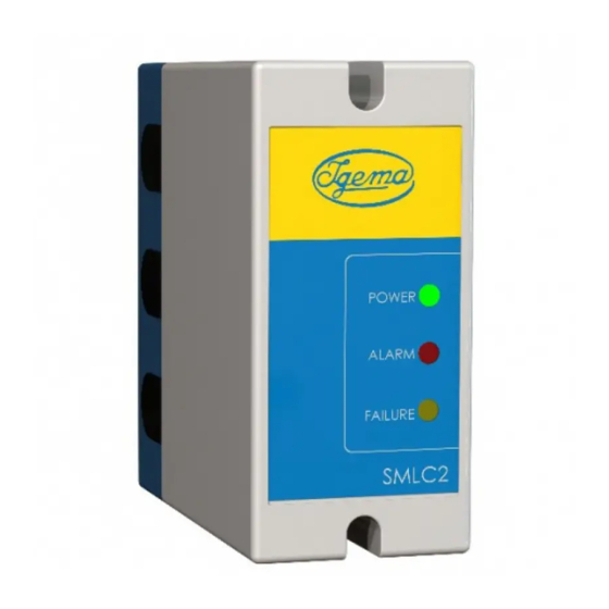
Page 11: Led-Display
This test is a background job and only an error detection will be displayed. Because of this special first failure safe design manual tests are not necessary so there are no test switches on the SMLC2.. 4.2 LED-Display... -
Page 12: Assembly And Installation
5. Assembly and Installation The limiter is supplied in a plastic plug-in housing for fitting into switch cabinets. The housing is designed for quick fitting with a spring catch for the DIN EN 50022 standard 35 mm carrier rail and for screw fixing on a mounting plate. 5.1 Installation dimensions and descriptions Base Front view... -
Page 13: Installation
5.2 Installation Ensure protection class in accordance with current regulations. Danger With snap fixing for standard DIN EN 50022 35 mm carrier rail Fix device on standard carrier rail by means of the snap fixing (4). Release fixing screws (3) and pull hood (7) from holder (5). - Without snap fixing Release fixing screws (3) and pull hood (7) from holder (5) Release screws (1) and remove snap fixing (4). -
Page 14: Assignment Plan
SMHL2 Mains voltage: see data plate Safety chain Signalling electrical connection: shielded cable 4 x 0,75mm2 ● e.g. Helutherm 145 Multi-C; IGEMA Art.Nr. 40-55214 1 2 3 Lead connection at probe plug EL030 oder EL19-2 1 Screw 2 Probe plug... -
Page 15: Procedure
• Pierce or pull out cable feedthrough (6) and feed connection cable through. Check supply voltage. See name plate for allowable voltage. Use shielded connection cable (4 x 0,75 mm²) to the electrode (z.B. Helutherm 145 Multi-C - IGEMA Art.No. 40-55214). • Length of connecting line max. 100 m. -
Page 16: Fitting The Electrode
5.4 Fitting the electrode It is essential to remove the protective tube for transport before installation! Danger If several electrodes are screwed into a flange the probe plugs (2) and the associated probes should be labelled to prevent confusion! Danger EL968 and MS015A/B: check separate Installation and Operating instruction Fixing the electrode extension (9) Screw... -
Page 17: Fixing Elements For Mounting Probes
5.5 Fixing elements for mounting probes The flanges, seals, screws and nuts listed in the table below are designed in accordance with DIN EN 12952 und 12953. Flanges according to DIN Form Threaded hole Material EN1092-1 according to drilling EN1092-1 1.0460 plan 1 100 / 160... -
Page 18: Mounting In The Add-On Housing
Screws according to DIN Quantity Dimension Material M16 x 75 M20 x 100 1.7709 100/160 M24 x 110 M20 x 90 1.7709 M24 x 110 100/160 2510 LM27 x 145 Ck 35 Nuts according to DIN Quantity Dimension Material EN 24032 1.7258 100/160 EN 24032... - Page 19 Illustration of add-on-housing Materials Flange 1.0460 Pipes St35.8 / 16 Mo 3 (according to pressure range) Stainless steel and ASME-compliant materials upon request.
- Page 20 Construction dimensions Construction dimensions min. mm d 60,3 114,3 Process connection M1 DIN sealing form Form B1 DIN EN 1092-1 Type 11 Form B2 Process connection M2 DIN sealing form Form B1 DIN EN 1092-1 Type 11 Form B2 On request ASME-compliant flanges, weld-on ends or DIN or ASME-compliant socket welding on the process connection M2 are also an option.
-
Page 21: Shortening The Electrode Extension
5.7 Shortening the electrode extension Always depressurise the boiler / add-on housing and allow it to cool down before dismantling the probe! The Probe is hot during operation! Severe burns at hands or arms are possible. During dismantling of the probe steam or hot water may escape! Danger Severe burns of the whole body are possible. -
Page 22: Configuration
6. Configuration The preset switch-off time of 4 sec can be changed. It is to be agreed upon with the local expert. Vorsicht Setting the switch-off time: • Open SMHC2. To do this, release the fixing screws (3) and pull the hood (7) off the holder (5) –with the device disconnected from the power supply (see chap. -
Page 23: Device Data - Probe
230V AC (-15% +10%), 50/60Hz* Power consumption: Measuring cable (data exchange): shielded connection cable to probe 4x0,75 mm² (e.g. Helutherm 145 Multi-C; IGEMA Art. No. 40-55214) Electrical connection: 12 pole screw terminal strip Protection class: IP40 in accordance with EN 60529 (protection... -
Page 24: Sil- Characteristics
7.3 SIL- characteristics Type B Low demand mode: PFD 2,05*10 High demand mode: PFH 5,18*10 Proof-Test_Intervall: T1 8760 h 7.4 Maximum ratings of potential free contacts Safety chain Switching voltage (max.) 250 V AC 25 V DC 300 V DC Switching current (max.) 6 A* ohmic 0,1 A... -
Page 25: Fault Analysis And Rectification
In the case of wearing and replacement parts, the warranty is limited to material and construction faults. Level probes are wearing parts and are not subject to warranty. This high-quality IGEMA product was designed, manufactured and tested with the application of the QM System guidelines in accordance with DIN EN ISO 9001:2015. -
Page 26: Conformity Declaration
10. Conformity declaration... -
Page 27: Certificates
11. Certificates PED Type Examination:... - Page 28 SIL 3 Zertifizierung:...
-
Page 29: Annex
12. Annex Devices necessary for a system without permanent surveillance (72h): Device Alternative Operating conditions ASME direct water level always gauge* direct water level 2 oblique water level always gauge gauges** LLW-Limiter always LLW-Limiter Level control 24h+72h HHW-prevention 24h+72h TDS limitation Direktanzeiger sind Geräte, bei denen optisch (mit dem Auge) direkt der Füllstand des Kesselwassers abgelesen werden kann. - Page 32 IGEMA GmbH Antwerpener Str. 1 Fon.: +49 2501 92424-0 48163 Münster Fax.: +49 2501 92424-99 Deutschland info@igema.com www.igema.com...
Need help?
Do you have a question about the SMLC2 and is the answer not in the manual?
Questions and answers