
Subscribe to Our Youtube Channel
Related Manuals for CAME AXI Series


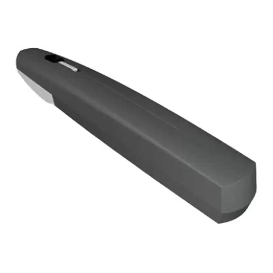
Summary of Contents for CAME AXI Series
- Page 1 Motoriduttore per cancelli a battente FA01007M04 Serie AXI IT Italiano AXI20DGS - AXI25DGS EN English FR Français RU Pусский MANUALE DI INSTALLAZIONE...
- Page 2 =============== Consegnare queste istruzioni al cliente fi nale =============== SBLOCCO MANUALE DEL MOTORIDUTTORE ⚠ L’attivazione dello sblocco manuale può provocare un movimento incontrollato del cancello a causa di anomalie meccaniche o di uno sbilanciamento. SBLOCCO (fi gura - Aprire lo sportello, inserire la chiave trilobata e ruotarla - Tirare in fuori la leva di sblocco.
-
Page 4: Avvertenze Generali Per L'installatore
AVVERTENZE GENERALI PER L'INSTALLATORE ⚠ ATTENZIONE! Importanti istruzioni di sicurezza. Seguire tutte le istruzioni in quanto un’installazione non corretta può portare a lesioni gravi. Prima di procedere leggere anche le avvertenze generali per l’utilizzatore. ’ L PRODOTTO DEVE ESSERE DESTINATO SOLO ALL USO PER IL QUALE È... - Page 5 2006/42/CE. A ’ NORMA ARMONIZZATA NELLA IRETTIVA ACCHINE SSICURARSI CHE L AUTOMAZIONE SIA STATA REGOLATA ADEGUATAMENTE E CHE I DISPOSITIVI DI SICUREZZA E PROTEZIONE COSÌ COME LO SBLOCCO MANUALE • A ’ FUNZIONINO CORRETTAMENTE PPLICARE UN ETICHETTA PERMANENTE CHE DESCRIVA COME USARE IL MECCANISMO •...
-
Page 6: Limiti D'impiego
LEGENDA Questo simbolo indica parti da leggere con attenzione. ⚠ Questo simbolo indica parti riguardanti la sicurezza. ☞ Questo simbolo indica cosa comunicare all’utente. Le misure, se non diversamente indicato, sono in millimetri. DESCRIZIONE Motoriduttore irreversibile con encoder per cancelli a battente. Cover in alluminio e ABS, sistema di riduzione con vite senza fine, corona e coppia conica. -
Page 7: Dati Tecnici
DATI TECNICI Tipo AXI20DGS AXI25DGS Grado di protezione (IP) Alimentazione quadro (V - 50/60 Hz) 230 AC Alimentazione motore (V) 24 DC Assorbimento max (A) Potenza max (W) Intermittenza/Lavoro (%) Tempo di apertura a 90° (s) Temperatura di esercizio (°C) -20 ÷... -
Page 8: Impianto Tipo
IMPIANTO TIPO 1. Motoriduttore 2. Quadro comando 3. Trasmettitore 4. Selettore a chiave 5. Lampeggiatore 6. Fotocellule 7. Pozzetto di derivazione ⑥ 8. Battute di arresto meccanico ⑥ ⑤ ① ⑧ ⑥ ④ ① ② ③ ⑧ ⑥ ⑦ INDICAZIONI GENERALI PER L'INSTALLAZIONE ⚠... - Page 9 TIPO E SEZIONE MINIMA CAVI lunghezza cavo Collegamento < 20 m 20 < 30 m Alimentazione scheda elettronica 230 V AC 3G x 1,5 mm 2 3G x 2,5 mm 2 (1P+N+PE) 2 x 0,5 mm 2 Dispositivi di segnalazione 2 x 0,5 mm 2 Dispositivi di comando (TX = 2 x 0,5 mm 2 )
- Page 10 INSTALLAZIONE Le seguenti illustrazioni sono solo esempi, in quanto lo spazio per il fissaggio del motoriduttore e degli accessori varia a seconda della zona di installazione. Spetta all’installatore scegliere la soluzione più adatta. POSA DEI TUBI CORRUGATI Preparare le scatole di derivazione e tubi corrugati necessari per i collegamenti provenienti dal pozzetto di derivazione.
- Page 11 Fissare la staffa al pilastro ❶ con viti e tasselli adeguati. Se il pilastro è di metallo, la staffa può essere saldata. Nota: i fori sulla staffa permettono una ulteriore variazione dell'angolo di apertura dell'anta. Fissare oppure saldare la staffa al cancello ❷ . ❷...
- Page 12 Aprire l'anta (i grani dei fermi meccanici sono allentati) e infi lare il perno nel foro della staff a cancello. . Fissare con la rondella UNI 6593 Ø 10 e la vite UNI 5739 M10 X 10 fornite DETERMINAZIONE DEI PUNTI DI FINECORSA Prima di procedere con la determinazione dei punti di fi...
- Page 13 ⚠ NON RIMUOVERE la cover 2 senza averla fatta scorrere. ❹ ❻ ⚠ ❺ In apertura In chiusura Raggiungere il punto di apertura anta desiderato e Chiudere completamente l'anta e portare il fermo portare il fermo meccanico in battuta con la slitta di meccanico in battuta con la slitta di azionamento.
- Page 14 COLLEGAMENTI AL QUADRO COMANDO COLLEGAMENTO DI DUE MOTORIDUTTORI M1 N1 ENC1 M2 N2 ENC2 Motoriduttore con encoder (M2) 24 V DC, ritardato in chiusura. Motoriduttore con encoder (M1) 24 V DC, ritardato in apertura. COLLEGAMENTO DI UN MOTORIDUTTORE M2 N2 ENC2 Motoriduttore con encoder (M2) 24 V DC...
- Page 15 COLLEGAMENTO PER APERTURA VERSO L'ESTERNO ⚠ Rilevare le quote A e B. Tagliare e fissare la staffa pilastro integrandola con una staffa supplementare (non fornita). Aprire il cancello (max 90°), rilevare la quota E e determinare il punto di fissaggio della staffa cancello. Fissare la staffa.
- Page 16 OPERAZIONI FINALI FISSAGGIO DELLE COVER Terminati i collegamenti elettrici e la messa in funzione, inserire le cover come di seguito indicato ⚠ NON INSERIRE le cover senza averle fatte scorrere. ❷ ❸ ⚠ ❶ ⚠ ❺ ❹ ❻...
-
Page 17: Smaltimento Dell'imballo
Ambientale certificato e conforme alla norma UNI EN ISO 14001 a garanzia del rispetto e della tutela dell’ambiente. Vi chiediamo di continuare l’opera di tutela dell’ambiente, che CAME considera uno dei fondamenti di sviluppo delle proprie strategie operative e di mercato, semplicemente osservando brevi indicazioni in materia di smaltimento: SMALTIMENTO DELL’IMBALLO... - Page 20 I contenuti del manuale sono da ritenersi suscettibili di modifica in qualsiasi momento senza obbligo di preavviso. CAME S.p.A. Via Martiri Della Libertà, 15 31030 Dosson di Casier - Treviso - Italy tel. (+39) 0422 4940 - fax. (+39) 0422 4941...
- Page 21 Gear motor for swing gates FA01007-EN AXI series AXI20DGS - AXI25DGS EN English INSTALLATION OPERATION AND MAINTENANCE MANUAL...
- Page 22 =============== Hand these instructions to the end user =============== MANUALLY RELEASING THE GEAR MOTOR ⚠ Manually releasing the gate may cause an uncontrolled movement of the gate due to possible mechanical anomalies or unbalancing. RELEASE (fi gure - Open the hatch, fi t the trilobe key and turn it - Take out the release tab.
- Page 24 GENERAL PRECAUTIONS FOR INSTALLERS ⚠ WARNING! Important safety instructions. Follow all of these instructions. Improper installation can cause serious bodily harm. Before continuing, also read the general precautions for users. HIS PRODUCT MUST ONLY BE USED FOR ITS SPECIFICALLY INTENDED PURPOSE NY OTHER USE IS DANGEROUS S.P.A.
- Page 25 THE NEXT FIGURE SHOWS THE MAIN HAZARD POINTS FOR PEOPLE Danger of high voltage Danger of foot crushing Danger of hand entrapment...
-
Page 26: Intended Use
This symbol shows which parts to read carefully. ⚠ This symbol shows which parts describe safety issues ☞ This symbol shows which parts to tell users about. The measurements, unless otherwise stated, are in millimeters. DESCRIPTION Encoder-fitted irreversible gearmotor for swing gates. Aluminium and ABS cover, worm screw based reduction system, crown and conical torque. -
Page 27: Technical Data
TECHNICAL DATA Type AXI20DGS AXI25DGS Protection rating (IP) Control panel power supply (V - 50/60 Hz) 230 AC Input voltage motor (V) 24 DC Max draw (A) Maximum power (W) Duty cycle (%) Opening time at 90° (s) Operating temperature (°C) -20 to +55 Apparatus class Reduction ration (i) -
Page 28: Standard Installation
STANDARD INSTALLATION 1. Gear motor 2. Control panel 3. Transmitter 4. Key-switch selector 5. Flashing light 6. Photocells 7. Junction pit ⑥ 8. Mechanical gate stops ⑥ ⑤ ① ⑧ ⑥ ④ ① ② ③ ⑧ ⑥ ⑦ GENERAL INSTALLATION INDICATIONS ⚠... - Page 29 CABLE TYPES AND MINIMUM SECTIONS cable length Connection < 20 m 20 < 30 m Input voltage for 230 V AC control board 3G x 1.5 mm 2 3G x 2.5 mm 2 (1P+N+PE) 2 x 0.5 mm 2 Signaling devices 2 x 0.5 mm 2 Command and control devices (TX = 2 x 0.5 mm 2 )
- Page 30 INSTALLATION The following illustrations are mere examples in that the space for anchoring the operator and accessories varies depending on the installation area. It is up to the installer to find the most suitable solution. CORRUGATED TUBE LAYING Set up the junction boxes and corrugated tubes you will need to make connections coming from the junction pit. To connect the gearmotor we suggest a Ø...
- Page 31 Fasten the bracket to the post ❶using suitable anchors and screws. If the post is made of metal, the bracket can be welded to it. Note: the holes on the bracket are for further opening angle variations of the gate leaf. Fasten or weld the bracket to the gate ❷...
- Page 32 Open the gate leaf (the grub screws on the mechanical stops are loose) and fi t the pin into the gate bracket. Fasten using the UNI6593 washer Ø 10 and the supplied UNI 5739 M10 X 10 bolt b . ESTABLISHING THE LIMIT-SWITCH POINTS Before establishing the endstop points, you need to: release the gearmotor (see paragraph on manually releasing it) and remove covers 1 and 2 while carefully following the illustrations.
- Page 33 ⚠ DO NOT REMOVE cover 2 without fi rst sliding it. ❹ ❻ ⚠ ❺ For closing For opening Close the gate leaf completely and rest it against the Reach the gate leaf opening point you want and take mechanical stop using the slide guide. Fasten the the mechanical stop to rest using the slide guide.
- Page 34 CONNECTIONS TO THE CONTROL PANEL CONNECTING TWO GEARMOTORS M1 N1 ENC1 M2 N2 ENC2 Gearmotor with encoder (M2) 24 V DC, delayed when closing. Gearmotor with encoder (M1) 24 V DC, delayed when opening. CONNECTING ONE GEARMOTOR M2 N2 ENC2 Gearmotor with encoder (M2) 24 V DC...
- Page 35 CONNECTION FOR OPENING OUTWARDS ⚠ Establish the quotas A and B. by supplementing it with an additional bracket b (not issued). Cut and fasten post bracket Open the gate (max 90°), establish the quota E and establish the gate bracket fastening point. Fasten the bracket. Opening (°) (mm)
- Page 36 FINAL OPERATIONS FASTENING THE COVERS Once you have completed all electrical connections and commissioning, fit the covers as shown here ⚠ YOU MUST fi rst slide the covers forward and then snap them down into place. ❷ ❸ ⚠ ❶ ⚠...
-
Page 37: Dismantling And Disposal
UNI EN ISO 14001 standard to ensure the environment is safeguarded. Please continue safeguarding the environment. At CAME we consider it one of the fundamentals of our operating and market strategies. Simply follow these brief disposal guidelines:... - Page 40 The contents of this manual may change, at any time, and without notice. CAME S.p.A. Via Martiri Della Libertà, 15 31030 Dosson di Casier - Treviso - Italy tel. (+39) 0422 4940 - fax. (+39) 0422 4941...
- Page 41 Motoréducteur pour portails battants FA01007-FR Série AXI AXI20DGS - AXI25DGS FR Français MANUEL D'INSTALLATION, D'UTILISATION ET D'ENTRETIEN...
- Page 42 =============== Remettre ces instructions au client fi nal =============== DÉBRAYAGE MANUEL DU MOTORÉDUCTEUR ⚠ L'activation du débrayage manuel peut provoquer un mouvement incontrôlé du portail à cause d’anomalies mécaniques ou d’un déséquilibrage. DÉBRAYAGE (fi gure ) - Ouvrir le volet, introduire le triangle et le tourner - Tirer le levier de déblocage.
- Page 44 INSTRUCTIONS GÉNÉRALES POUR L'INSTALLATEUR ⚠ ATTENTION ! Consignes de sécurité importantes. Suivre toutes les instructions étant donné qu'une installation incorrecte peut provoquer de graves lésions. Avant toute opération, lire également les instructions générales réservées à l’utilisateur. E PRODUIT NE DEVRA ÊTRE DESTINÉ QU À...
- Page 45 • P INSTALLÉS À UNE HAUTEUR MINIMUM DE M ET ÊTRE INACCESSIBLES AU PUBLIC OUR PASSER LE TEST DES ’ FORCES D IMPACT UTILISER UN BORD SENSIBLE APPROPRIÉ CORRECTEMENT INSTALLÉ ET EFFECTUER LES RÉGLAGES • A NÉCESSAIRES VANT DE LIVRER L INSTALLATION À...
-
Page 46: Utilisation Prévue
LÉGENDE Ce symbole indique des parties à lire attentivement. ⚠ Ce symbole indique des parties concernant la sécurité. ☞ Ce symbole indique ce qui doit être communiqué à l'utilisateur. Les dimensions sont exprimées en millimètres, sauf indication contraire. DESCRIPTION Motoréducteur irréversible avec encodeur pour portails battants. -
Page 47: Données Techniques
DONNÉES TECHNIQUES Type AXI20DGS AXI25DGS Degré de protection (IP) Alimentation armoire (V - 50/60 Hz) 230 AC Alimentation moteur (V) 24 DC Absorption max. (A) Puissance max. (W) Intermittence/Fonctionnement (%) Temps d’ouverture à 90° (s) Température de fonctionnement (°C) -20 ÷ +55 Classe de l’appareil Rapport de transmission (i) 1/36... -
Page 48: Installation Standard
INSTALLATION STANDARD 1. Motoréducteur 2. Armoire de commande 3. Émetteur 4. Sélecteur à clé 5. Clignotant 6. Photocellules 7. Boîtier de dérivation ⑥ 8. Butées mécaniques ⑥ ⑤ ① ⑧ ⑥ ④ ① ② ③ ⑧ ⑥ ⑦ INSTRUCTIONS GÉNÉRALES POUR L'INSTALLATION ⚠... - Page 49 TYPE ET SECTION MINIMALE DES CÂBLES longueur câble Connexion < 20 m 20 < 30 m Alimentation carte électronique 230 VAC 3G x 1,5 mm 2 3G x 2,5 mm 2 (1P+N+PE) 2 x 0,5 mm 2 Dispositifs de signalisation 2 x 0,5 mm 2 Dispositifs de commande (TX = 2 x 0,5 mm 2 )
- Page 50 INSTALLATION Les illustrations suivantes ne sont que des exemples étant donné que l'espace pour la fixation du motoréducteur et des accessoires varie en fonction de la zone d'installation. C'est donc l'installateur qui doit choisir la solution la plus indiquée. POSE DES GAINES ANNELÉES Prévoir les boîtes de jonction et les tuyaux annelés nécessaires pour les raccordements issus du boîtier de dérivation.
- Page 51 Fixer l'étrier au pilier ❶ à l'aide des vis et des chevilles spécifiques. En cas de pilier en métal, il est possible de souder l'étrier. Remarque : les trous prévus sur l'étrier permettent de varier l'angle d'ouverture du vantail. Fixer ou souder l'étrier sur le portail ❷ . ❷...
- Page 52 Ouvrir le vantail (les goujons des butées mécaniques sont desserrés) et introduire le goujon dans le trou de l'étrier portail. . Fixer à l'aide de la rondelle UNI 6593 Ø 10 et de la vis UNI 5739 M10 X 10 fournies DÉTERMINATION DES POINTS DE FIN DE COURSE Avant l'identifi...
- Page 53 ⚠ N’ENLEVER le couvercle 2 qu'après l'avoir fait glisser. ❹ ❻ ⚠ ❺ En phase d'ouverture En phase de fermeture Atteindre le point d'ouverture du vantail souhaité Fermer complètement le vantail et amener la butée et amener la butée mécanique contre le rail mécanique contre le rail d'actionnement.
- Page 54 CONNEXIONS À L'ARMOIRE DE COMMANDE CONNEXION DE DEUX MOTORÉDUCTEURS M1 N1 ENC1 M2 N2 ENC2 Motoréducteur avec encodeur (M2) 24 V DC, retardé à la fermeture. Motoréducteur avec encodeur (M1) 24 V DC, retardé à l'ouverture. CONNEXION D'UN MOTORÉDUCTEUR M2 N2 ENC2 Motoréducteur avec encodeur (M2) 24 V DC...
- Page 55 CONNEXION POUR L'OUVERTURE VERS L'EXTÉRIEUR ⚠ Mesurer les dimensions A et B. (non fourni). Couper et fixer l'étrier pilier et y ajouter un étrier supplémentaire Ouvrir le portail (90° maxi), mesurer la dimension E et identifier le point de fixation de l'étrier portail. Fixer l'étrier. Ouverture (°) (mm)
-
Page 56: Fixation Des Couvercles
OPÉRATIONS FINALES FIXATION DES COUVERCLES Au terme des branchements électriques et de la mise en fonction, mettre les couvercles comme indiqué ci-dessous. ⚠ N’APPLIQUER les couvercles qu’après les avoir fait glisser. ❷ ❸ ⚠ ❶ ⚠ ❺ ❹ ❻... -
Page 57: Élimination De L'emballage
Environnementale certifié et conforme à la norme UNI EN ISO 14001 qui garantit le respect et la sauvegarde de l'environnement. Nous vous demandons de poursuivre ces efforts de sauvegarde de l'environnement, que CAME considère comme l'un des fondements du développement de ses propres stratégies opérationnelles et de marché, en observant tout simplement de brèves indications en matière d'élimination :... - Page 60 Le contenu de ce manuel est susceptible de subir des modifications à tout moment et sans aucun préavis. CAME S.p.A. Via Martiri Della Libertà, 15 31030 Dosson di Casier - Treviso - Italy tel. (+39) 0422 4940 - fax. (+39) 0422 4941...
- Page 61 Привод для распашных ворот FA01007-RU Серия AXI AXI20DGS - AXI25DGS ИНСТРУКЦИЯ ПО МОНТАЖУ, ЭКСПЛУАТАЦИИ И ТЕХНИЧЕСКО- RU Русский МУ ОБСЛУЖИВАНИЮ...
- Page 62 ======== Передайте эти инструкции конечному пользователю =============== РУЧНАЯ РАЗБЛОКИРОВКА ПРИВОДА ⚠ Активация ручной разблокировки может привести к неконтролируемому движению автоматики, вызванному механическими неисправностями или нарушением балансировки. РАЗБЛОКИРОВКА (рис. ) - Откройте дверцу, вставьте трехгранный ключ и поверните его. - Потяните на себя ручку разблокировки. БЛОКИРОВКА...
- Page 64 Прежде чем продолжить, внимательно прочитайте общие предупрежде- ния для пользователя. Э . Л ТО ИЗДЕЛИЕ ДОЛЖНО ИСПОЛЬЗОВАТЬСЯ ИСКЛЮЧИТЕЛЬНО ПО НАЗНАЧЕНИЮ ЮБОЕ ДРУГОЕ ПРИМЕНЕНИЕ . CAME S. РАССМАТРИВАЕТСЯ КАК ОПАСНОЕ НЕ НЕСЕТ НИКАКОЙ ОТВЕТСТВЕННОСТИ ЗА УЩЕРБ ВЫЗВАН . • П НЫЙ НЕПРАВИЛЬНЫМ...
- Page 65 .) • Д ТРАНСФОРМАТОРОМ И Т П ЛЯ ПОДКЛЮЧЕНИЯ К СЕТИ ЭЛЕКТРОПИТАНИЯ НЕОБХОДИМО ПРЕДУСМОТРИТЕ АВТОМАТИЧЕСКИЙ ВЫКЛЮЧАТЕЛЬ С РАССТОЯНИЕМ МЕЖДУ КОНТАКТАМИ НЕ МЕНЕЕ ММ ОБЕСПЕЧИВАЮЩИЙ • В ЗАЩИТУ ОТ ПЕРЕНАПРЯЖЕНИЯ СТЕПЕНИ СЕ УСТРОЙСТВА УПРАВЛЕНИЯ И КОНТРОЛЯ ДОЛЖНЫ УСТАНАВ 1,85 ЛИВАТЬСЯ НА РАССТОЯНИИ НЕ МЕНЕЕ М...
-
Page 66: Условные Обозначения
УСЛОВНЫЕ ОБОЗНАЧЕНИЯ Этот символ обозначает раздел, требующий особого внимания. ⚠ Этот символ обозначает раздел, связанный с вопросами безопасности. ☞ Этот символ обозначает раздел, предназначенный для ознакомления конечного пользователя. Все размеры приведены в мм, если не указано иное. ОПИСАНИЕ Самоблокирующийся мотор-редуктор с энкодером для распашных ворот. Крышки... -
Page 67: Технические Характеристики
ТЕХНИЧЕСКИЕ ХАРАКТЕРИСТИКИ Модель AXI20DGS AXI25DGS Класс защиты (IP) Напряжение электропитания (В, 50/60 Гц) ~230 Электропитание мотора (В) =24 В Макс. потребляемый ток (А) Макс. мощность (Вт) Интенсивность использования (%) Время открывания на 90° (с) Диапазон рабочих температур (°C) -20 — +55 Класс устройства Передаточное... -
Page 68: Предварительные Проверки
ВАРИАНТ ТИПОВОЙ УСТАНОВКИ 1. Мотор-редуктор 2. Блок управления 3. Пульт ДУ 4. Ключ-выключатель 5. Сигнальная лампа 6. Фотоэлементы 7. Разветвительный колодец ⑥ 8. Механические упоры ⑥ ⑤ ① ⑧ ⑥ ④ ① ② ③ ⑧ ⑥ ⑦ ОБЩИЕ ИНСТРУКЦИИ ПО МОНТАЖУ ⚠... - Page 69 ТИП И МИНИМАЛЬНОЕ СЕЧЕНИЕ КАБЕЛЕЙ Длина кабеля Подключение < 20 м 20 < 30 м Электропитание платы управления, ~230 В 3G x 1,5 мм 2 3G x 2,5 мм 2 (1P+N+PE) 2 x 0,5 мм 2 Устройства сигнализации 2 x 0,5 мм 2 Устройства...
- Page 70 УСТАНОВКА Приведенные ниже рисунки носят иллюстративный характер, так как пространство для крепления автоматики и дополнительных принадлежностей может меняться от случая к случаю. Выбор наиболее подходящего решения должен осуществляться установщиком на месте. ПРОКЛАДКА ГОФРИРОВАННЫХ ТРУБ Подготовьте разветвительные коробки и гофрированные трубы, необходимые...
- Page 71 Прикрепите кронштейн к столбу ❶ с помощью надлежащих винтов и дюбелей. Если столб ворот металлический, приварите к нему кронштейн. Примечание: отверстия в заднем кронштейне позволяют дополнительно изменять угол открывания створки. Прикрепите или приварите кронштейн к столбу ворот ❷. ❷ ❶ КРЕПЛЕНИЕ...
- Page 72 Откройте створку (отвернув предварительно регулировочные винты механических упоров) и вставьте стержень в отверстие переднего кронштейна. . Зафиксируйте его с помощью прилагаемых шайбы UNI 6593 Ø 10 и винта UNI 5739 M10 X 10 РЕГУЛИРОВКА КРАЙНИХ ПОЛОЖЕНИЙ Прежде чем приступить к регулировке конечных положений, необходимо: разблокировать привод (см. пункт...
- Page 73 ⚠ ПЕРЕД ТЕМ КАК СНЯТЬ крышку 2, обязательно ❹ сдвиньте ее. ❻ ⚠ ❺ При открывании При закрывании Отведя створку в желаемое положение Плотно закрыв створку, установите механический открывания, установите механический упор упор вплотную к каретке и закрутите вплотную к каретке и регулировочные...
- Page 74 ПОДКЛЮЧЕНИЕ К БЛОКУ УПРАВЛЕНИЯ ПОДКЛЮЧЕНИЕ ДВУХ ПРИВОДОВ M1 N1 ENC1 M2 N2 ENC2 Привод с энкодером (M2) =24 В, с задержкой при закрывании. Привод с энкодером (M1) =24 В, с задержкой при открывании. ПОДКЛЮЧЕНИЕ ОДНОГО ПРИВОДА M2 N2 ENC2 Привод с энкодером (M2) =24 В...
- Page 75 ПОДКЛЮЧЕНИЕ ПРИ ОТКРЫВАНИИ ВОРОТ НАРУЖУ ⚠ Определите расстояния A и B. (не Обрежьте и прикрепите задний кронштейн , дополнив его дополнительным кронштейном поставляется). Откройте ворота (на макс. 90°), измерьте расстояние E и определите точку крепления переднего кронштейна. Прикрепите передний кронштейн. Открывание (°) (мм) Выполните...
-
Page 76: Заключительные Работы
ЗАКЛЮЧИТЕЛЬНЫЕ РАБОТЫ КРЕПЛЕНИЕ КРЫШКИ После выполнения всех электрических подключений и подготовки системы к работе установите крышку, как показано на рисунке. ⚠ НЕ ВСТАВЛЯЙТЕ крышки, не сдвинув их вперед. ❷ ❸ ⚠ ❶ ⚠ ❺ ❹ ❻... -
Page 77: Утилизация Упаковки
УТИЛИЗАЦИЯ ☞ CAME S.p.A. имеет сертификат системы защиты окружающей среды UNI EN ISO 14001, гарантирующий экологическую безопасность на ее заводах. Мы просим, чтобы вы продолжали защищать окружающую среду. САМЕ считает одним из фундаментальных пунктов стратегии рыночных отношений выполнение этих кратких руководящих... - Page 80 Содержание данного руководства может быть изменено в любое время без предварительного уведомления. CAME S.p.A. Via Martiri Della Libertà, 15 31030 Dosson di Casier - Treviso - Italy tel. (+39) 0422 4940 - fax. (+39) 0422 4941...
Need help?
Do you have a question about the AXI Series and is the answer not in the manual?
Questions and answers