Table of Contents
Advertisement
Quick Links
© 2020
burster
präzisionsmesstechnik gmbh & co kg
All rights reserved
Valid from:
December 7, 2020
OPERATION MANUAL
Fieldbus controller
Model 9251
Manufacturer:
burster
präzisionsmesstechnik gmbh & co kg
Talstr. 1-5
76593 Gernsbach
Germany
Tel.: +49 7224 645-0
Fax: +49 7224 645-88
Email: info@burster.de
www.burster.com
Postfach 1432
76587 Gernsbach
Germany
4021-BA9251EN-5999-121532
Advertisement
Table of Contents

Related Manuals for Burster 9251


Summary of Contents for Burster 9251
- Page 1 OPERATION MANUAL Fieldbus controller Model 9251 Manufacturer: © 2020 burster burster präzisionsmesstechnik gmbh & co kg präzisionsmesstechnik gmbh & co kg All rights reserved Talstr. 1-5 Postfach 1432 76593 Gernsbach 76587 Gernsbach Germany Germany Valid from: December 7, 2020 Tel.: +49 7224 645-0 Fax: +49 7224 645-88 Email: info@burster.de...
- Page 2 “product”) are the result of targeted development and meticulous research. From the date of delivery, burster provides a warranty for the proper condition and functioning of these products covering material and production defects for the period specified in the warranty document accompanying the product.
- Page 3 of 47...
-
Page 4: Table Of Contents
1.1 Symbols used in the operating manual .................... 7 Signal words ......................... 7 Pictograms ........................... 8 1.2 Symbols on the 9251 fieldbus controller ..................8 Conventions used in the operating manual ................. 8 Introduction ............................9 2.1 Intended use ............................. 9 2.2 Customer service .......................... - Page 5 6.2 Planning a PROFINET network ..................... 22 6.3 PROFINET fieldbus-specific LED functions ................... 22 6.4 Cyclical data transmission from the 9251 fieldbus controller to the control system ...... 23 Data packets for data transmission from the 9251 fieldbus controller to the control system using the “short”...
- Page 6 Data protocol for data transmission from the 9251 fieldbus controller to the control system Data protocol for data transmission from the 9250 instrumentation amplifier to the control system ..........................36 Data protocol for data transmission from the control system to the 9251 fieldbus controller Data protocol for data transmission from the control system to the 9250 instrumentation amplifier ..........................
-
Page 7: For Your Safety
Property damage to the equipment or the surroundings will result if the hazard is not avoided. Note: It is important to heed these safety notices in order to ensure you handle the model 9251 fieldbus controller correctly. IMPORTANT: Follow the information given in the operating manual. -
Page 8: Pictograms
Pictograms Electric shock hazard Important, please note Observe the advice for protecting the model 9251 fieldbus controller. Symbols on the 9251 fieldbus controller Symbol Description See manual! It is essential to observe the information and notes in the operation manual for the model 9251 fieldbus controller. -
Page 9: Introduction
DANGER Only use the model 9251 fieldbus controller outside of potentially explosive • areas. The model 9251 fieldbus controller is not intended as a substitute for safety • devices and protective equipment. Use safety devices and protective equipment. • The model 9251 fieldbus controller is not intended for use in medical applications or where people are at risk. -
Page 10: Contact Person
+49 7224 645-88 Email: info@burster.de Download the test certificate You have the option to download the test certificate for your model 9251 fieldbus controller online. To do this, use the following link https://tinyurl.com/y45kumy6. You can then download the test certificate directly by entering the serial number. -
Page 11: Restrictions On Use
Disconnect the model 9251 fieldbus controller from the power supply before cleaning. Disconnect the model 9251 fieldbus controller from the power supply and use a dry cloth to clean the unit. NOTICE Do not immerse the model 9251 fieldbus controller in water or hold it under running water. -
Page 12: Unpacking
Please note the following when sending the model 9251 fieldbus controller in for repair: If there is a problem with the device, please attach a note to the housing of the model 9251 • fieldbus controller summarizing the fault. -
Page 13: Device Concept
Device concept Please refer to the model 9251 fieldbus controller data sheet for full details of dimensions, weight, degree of protection etc. Functional scope The model 9251 fieldbus controller serves as a bridge between cascadable model 9250 universal instrumentation amplifiers and Ethernet-based fieldbuses such as PROFINET, EtherCAT and EtherNet/IP. -
Page 14: Versions
Figure 2: QR code for 9251 fieldbus controller Power supply The model 9251 fieldbus controller can be operated with a voltage of 11 to 30 V DC. The maximum power consumption of the model 9251 fieldbus controller is 3 W. -
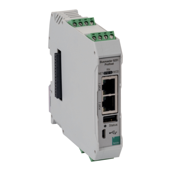
Page 15: Controls And Connections
Controls and connections Front view Figure 3: Front view of model 9251 fieldbus controller Label Description Fieldbus status indicator Fieldbus ports USB host Status LED Micro-USB port for configuration Internal bus connection e.g. for model 9250 instrumentation amplifier External inputs and outputs... -
Page 16: Terminal Assignment / Pin Assignment
Pin assignment model 9251 fieldbus controller Fieldbus status indicator The fieldbus status indicator on the model 9251 fieldbus controller depends on the chosen version. You can choose between the different fieldbuses PROFINET, EtherCAT and EtherNet/IP. See the respective fieldbus section for a detailed description of the status indicators. -
Page 17: Leds
Online (RUN) Table 4: Meaning of LEDs model 9251 fieldbus controller Status LED (normal operation) The status LED is a multi-color LED that tells you the status of the model 9251 fieldbus controller. Indicator Description Status LED flashing slowly green... -
Page 18: Grounding And Shielding
Grounding and shielding The model 9251 fieldbus controller is grounded via the mounting rail. Use suitable connecting cables for connecting communication interfaces and for controlling I/O signals. Ideally you should connect sensors using burster connecting cables and with a minimum length of cable. -
Page 19: Plc Outputs
PLC outputs The model 9251 fieldbus controller optionally (in conjunction with the analog input option) has two independent PLC outputs to which different functions can be assigned. The PLC outputs are only available with the optional analog input. The following functions are possible: •... -
Page 20: Using The Instrument For The First Time
Install the model 9251 fieldbus controller only on a grounded mounting rail in a grounded control cabinet. The model 9251 fieldbus controller must be installed on a grounded mounting rail in accordance with DIN EN 60715 in a grounded control cabinet. -
Page 21: Profinet
If the initialization was successful, the model 9250 instrumentation amplifiers show their channel number in the LED field. If the model 9251 fieldbus controller was not recognized, then the status LED on the model 9250 instrumentation amplifiers flashes continuously in a 1-1-1 pattern. When module detection is complete, the status LED flashes continuously and slowly. -
Page 22: Planning A Profinet Network
There is no connection between the model 9251 fieldbus controller and the master, or no power supply is connected. Green The model 9251 fieldbus controller is in RUN state and the connection to the master is established. Green, single flashes... -
Page 23: Cyclical Data Transmission From The 9251 Fieldbus Controller To The Control System
9250 instrumentation amplifier, and so on. Please note that there are only as many data blocks as there are devices. A combination of model 9251 fieldbus controller and model 9250 instrumentation amplifiers with four measuring channels is represented by five data blocks. -
Page 24: Data Packets For Data Transmission From The 9251 Fieldbus Controller To The Control System Using The "Short" Method
Data packets for data transmission from the 9251 fieldbus controller to the control system using the “short” method Content Length/Bytes ∑ Bytes Device status Measurement value (real)* Sum: 8 bytes Measurement counter* reserved Content Length/Bytes ∑ Bytes Device status Measurement value (real) -
Page 25: Data Packets For Data Transmission From The 9251 Fieldbus Controller To The Control System Using The "Extended" Method
Data packets for data transmission from the 9251 fieldbus controller to the control system using the “extended” method Content Length/Bytes ∑ Bytes Device status Measurement value (real)* Measurement counter* Sum: 136 bytes Measurement array counter* Measurement value array (real)* Content Length/Bytes ∑... -
Page 26: Complete Data Protocol For Data Transmission From The 9251 Fieldbus Controller To The Control System Using The "Short" Method
Live counter, will be incremented with every new measurement value Reserved Table 9: Complete data protocol (short) – model 9251 fieldbus controller – inputs Data protocol for data transmission from the 9250 instrumentation amplifier to the control system using the “short” method... -
Page 27: Data Protocol For Data Transmission From The 9251 Fieldbus Controller To The Control System Using The "Extended" Method
Data protocol for data transmission from the 9251 fieldbus controller to the control system using the “extended” method Address Length Description Offset (Bytes) STATUS 1 xxxx Bit0: TARE is active xxx1 xxxx Bit1: Error, analog input overload [bus coupler: overload]... -
Page 28: Data Protocol For Data Transmission From The 9250 Instrumentation Amplifier To The Control System Using The "Extended" Method
Data protocol for data transmission from the 9250 instrumentation amplifier to the control system using the “extended” method Address Length Description Offset (Bytes) STATUS 1 xxxx Bit0: TARE is active xxx1 xxxx Bit1: Measurement error xx1x xxxx Bit2: Warning: Ua/Ia is not related to input signal (due to input x1xx overload, peak hold mode, ADC inactive) xxxx... -
Page 29: Cyclical Data Transmission From The Control System To The 9251 Fieldbus Controller
Example: A 9251/9250 combination with four measurement channels is represented by five data blocks. The first data block corresponds to the model 9251 fieldbus controller, the remaining four correspond to the respective measurement channels of the model 9250 instrumentation amplifiers. -
Page 30: Data Protocol Cyclical Data For Data Transmission From The Control System To The 9250 Instrumentation Amplifier
New Real Value 2 – reserved and not used New Real Value 3 – reserved and not used Table 13: Data protocol cyclical data for data transmission from the control system to the model 9251 fieldbus controller Data protocol cyclical data for data transmission from the control system... -
Page 31: Data Protocol Acyclical Data 9251 Fieldbus Controller
Serial Number as ASCII String STR20 Software Version STR20 Additional Info (not supported yet) Binary Complete Configuration Table 15: Data protocol acyclical data model 9251 fieldbus controller Data protocol acyclical data 9250 instrumentation amplifier Index (dec) Type Size/Bytes Access Entry HW-ID of... -
Page 32: Ethercat
If the initialization was successful, the model 9250 instrumentation amplifiers show their channel number in the LED field. If the model 9251 fieldbus controller was not recognized, then the status LED on the model 9250 instrumentation amplifiers flashes continuously in a 1-1-1 pattern. When module detection is complete, the status LED flashes continuously and slowly. -
Page 33: Port Identification
Port identification The burster model 9251 fieldbus controller can be integrated into the fieldbus network via 2x RJ45 ports. Figure 11: Port assignment on model 9251 fieldbus controller EtherCAT fieldbus-specific LED functions Figure 12: EtherCAT LED functions Status Description The model 9251 fieldbus controller is in the INIT state or no power supply is connected. -
Page 34: Ethercat Pdo - Process Data Objects
9250 instrumentation amplifier, and so on. Please note that there are only as many data blocks as there are devices. A combination of model 9251 fieldbus controller and model 9250 instrumentation amplifiers with four measuring channels is represented by five data blocks. -
Page 35: Data Protocol For Data Transmission From The 9251 Fieldbus Controller To The Control System
Measurement value array (real) * only active with analog input option Table 18: Overview of the data protocol for data transmission from the model 9251 fieldbus controller to the control system Data protocol for data transmission from the 9251 fieldbus controller to... -
Page 36: Data Protocol For Data Transmission From The 9250 Instrumentation Amplifier To The Control System
Value no. 30 of measurement value array (real) Value no. 31 of measurement value array (real) Table 19: Complete data protocol for data transmission from the model 9251 fieldbus controller to the control system Data protocol for data transmission from the 9250 instrumentation... -
Page 37: Data Protocol For Data Transmission From The Control System To The 9251 Fieldbus Controller
Value no. 31 of measurement value array (real) Table 20: Complete data protocol for data transmission from the model 9250 instrumentation amplifier to the control system Data protocol for data transmission from the control system to the 9251 fieldbus controller Address Length... -
Page 38: Data Protocol For Data Transmission From The Control System To The 9250 Instrumentation Amplifier
New Real Value 3 – reserved and not used Table 21: Data protocol for data transmission from the control system to the model 9251 fieldbus controller Data protocol for data transmission from the control system to the 9250 instrumentation amplifier... -
Page 39: Ethercat Sdo - Service Data Objects
Index 0: Number of indices to read complete configuration 0x2076 Binary Index 1-135: Complete configuration in 4-byte pieces Table 24: Acyclical data of the model 9251 fieldbus controller Acyclical data 9250 instrumentation amplifier module 1 Index (hex) Type Size (Bytes) Access... -
Page 40: Acyclical Data 9250 Instrumentation Amplifier Module 2
1: Strain Gage 99: Bus Coupler 0x20D7 STR20 Serial Number as ASCII String 0x20D8 STR20 Software Version 0x20D9 STR20 Additional Info (not supported yet) Index 0: Number of indices to read complete configuration 0x20DA Binary Index 1-166: Complete configuration in 4-byte pieces Table 25: Acyclical data of the model 9250 instrumentation amplifier module 1 Acyclical data 9250 instrumentation amplifier module 2... -
Page 41: Acyclical Data 9250 Instrumentation Amplifier Module 4
Acyclical data 9250 instrumentation amplifier module 4 Index (hex) Type Size (Bytes) Access Entry 0x21F7 Real Minimum Value 0x21F8 Real Maximum Value 0x21F9 Real Tare Value 0x21FA Real Limit A Lower Value in [User Unit] 0x21FB Real Limit A Lower Value in [V] 0x21FC Real Limit A Upper Value in [User Unit]... -
Page 42: Acyclical Data 9250 Instrumentation Amplifier Module 7
0x22C6 Real Limit B Lower Value in [User Unit] 0x22C7 Real Limit B Lower Value in [V] 0x22C8 Real Limit B Upper Value in [User Unit] 0x22C9 Real Limit B Upper Value in [V] Channel Type 0: undefined / error 0x22CA UINT16 1: Strain Gage... -
Page 43: Ethercat Error Codes
0x2395 STR20 Additional Info (not supported yet) Index 0: Number of indices to read complete configuration 0x2396 Binary Index 1-166: Complete configuration in 4-byte pieces Table 32: Acyclical data of the model 9250 instrumentation amplifier module 8 EtherCAT error codes Error code ID of operant Object does not exist in the object dictionary... -
Page 44: Service Offering For The 9251 Fieldbus Controller
• Initial calibration and recalibration, including sensors To inquire about our customer services for your model 9251 fieldbus controller, please call our Service department on +49 7224 645-53, or email: service@burster.de (Germany only). If you are outside Germany, you should contact your burster agent (see also www.burster.com). -
Page 45: Technical Data
Technical data Please refer to the model 9251 fieldbus controller data sheet for specifications and technical data. You can obtain the latest data sheet and additional information on the model 9251 fieldbus controller at https://tinyurl.com/y65b5xys or simply use the QR code below:... -
Page 46: Accessories Available
Accessories available Please refer to the model 9251 fieldbus controller data sheet for data sheet for details of the accessories available. You can obtain the latest data sheet and additional information on the model 9251 fieldbus controller at https://tinyurl.com/y65b5xys or simply use the QR code below:... -
Page 47: Disposal
Disposal Battery disposal In Germany, the end user is legally obliged to return all used batteries, and it is illegal to dispose of batteries in the household waste. This law may also affect you as purchaser of the instrument described here. Please dispose of your used batteries properly and in accordance with national statutory regulations.
Need help?
Do you have a question about the 9251 and is the answer not in the manual?
Questions and answers