Burster 9251 PROFINET Series Operation Manual
Fieldbus-controller
Hide thumbs
Also See for 9251 PROFINET Series:
- Operation manual (47 pages) ,
- Operation manual (122 pages)
Advertisement
Quick Links
PROFINET Integration into TIA Portal
© 2020
burster
praezisionsmesstechnik gmbh & co kg
All rights reserved
Valid from:
26.10.2020
Applies to:
9251-VXX03
OPERATION MANUAL
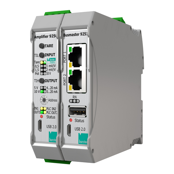
Fieldbus-Controller Model 9251
Manufacturer:
burster
präzisionsmesstechnik gmbh & co kg
Talstr. 1 - 5
76593 Gernsbach
Germany
Tel.: +49-7224-645-0
Fax.: +49-7224-645-88
Email: info@burster.com
www.burster.com
4003-BAPROFINETTIAEN-5999-101530
P.O. Box 1432
76587 Gernsbach
Germany
Advertisement

Related Manuals for Burster 9251 PROFINET Series


Summary of Contents for Burster 9251 PROFINET Series
- Page 1 & co kg präzisionsmesstechnik gmbh & co kg All rights reserved Talstr. 1 - 5 P.O. Box 1432 76593 Gernsbach 76587 Gernsbach Germany Germany Valid from: 26.10.2020 Tel.: +49-7224-645-0 Applies to: 9251-VXX03 Fax.: +49-7224-645-88 Email: info@burster.com www.burster.com 4003-BAPROFINETTIAEN-5999-101530...
-
Page 2: Table Of Contents
Table of Contents Introduction ............................... 3 Creating new project .......................... 4 Installation of GSDML files ......................... 6 Creation of network connections ......................7 Create a sample program ........................ 11 Further Examples ..........................17 Reading of ‘string’ data types ......................18 Read and Write of ‘real’... -
Page 3: Introduction
Introduction This quick start guide describes an approach how you can configure the 9251 via TIA Portal using the example of S7-1511 CPU. Please note that the samples here cannot be directly used in your production line because they have beed extremely simplified to reach a better understanding. Therefore, you may have to complete them by checking of status, error, length values etc. -
Page 4: Creating New Project
Creating new project Start the Totally Integrated Automation Protal, select Create New Project (a), assign the project a name (b) and click Create (c): of 22... - Page 5 Go to Devices & networks (a) on the left side select Add new device (b) and look for your CPU (c). Afterwards click the Add button (d). of 22...
-
Page 6: Installation Of Gsdml Files
Note: Please make sure that your GSDML file is compatible to the field bus firmware in the 9251. The latest GSDML file is available for download on www.burster.com. Also for compatibility reasons, uninstall all previous GSDML files of particular device if you have any! ... -
Page 7: Creation Of Network Connections
Creation of network connections Double click Device Configuration (a) in the project tree und switch to Network view (b) : of 22... - Page 8 Now select the burster_9251_Buscoupler device in the catalog and drag & drop it into the working area (a): Select an Ethernet port on the S7 and hold the left mouse button down to connect the S7 with 9251: of 22...
- Page 9 Note: Check if devices also connected physically to the right ports. You find the port number assignment directly on the device front side. Next, click on the burster-9251 device (a) and then switch to Device view (b) Now, remove the entry BusCoupler Data short 1 (a) from the Device overview ...
- Page 10 in addition, insert the entry BusCoupler Data extended (a) into the Device overview table (b), you can drag it or just double click on the entry: Note: In comparison to the “short” version, allows the extended version the receiving of 32 last measurement values, so you can expand this example to show all 32 last values.
-
Page 11: Create A Sample Program
Create a sample program In this section, you will learn how to create a simple program to read a measurement value from the analogue input of the bus controller. You will need to refer Cyclic Input Data of the 9251 PROFINET Interface Documentation manual to understand the meaning of input bytes. - Page 12 Select in the new window Organization block (a) and then Cyclic interrupt (b). As language set SCL (c), change the cyclic time to 1.000.000 µs (d) and click OK (e): Declare a new variable meas_val under PLC Tags of 22...
- Page 13 then type in the following source code in the code field of the new block: "meas_val" := DWORD_TO_REAL("INPUT_BYTES_2_5"); Please note: the addresses may be different. You have to check them in the Device view → Device overview of the 9251. You will also see that the TIA-Editor replaces the input addresses with tags.
- Page 14 Before you load the project into the CPU you have to set the IP address of your CPU. To do this please go to Device view and select Ethernet addresses (a) in General tab. Set now the IP- Address and a subnet mask(b) for your PLC: of 22...
- Page 15 To load the configuration into the CPU select it first go to Online → Download to device and click on Start search (a) to look for your controller. Then select the controller and click on Load (b): To watch the measurement value, go to Watch and force tables (a) → Add new watch table (a) und add the variable meas_val to the table (b): of 22...
- Page 16 Now click on “Go online” (a) and then “Monitor all” (b) to watch the value of meas_val Measurement value of analogue input of 22...
-
Page 17: Further Examples
In the followed examples, a Hardware-ID is used to access a certain slot. To find this, please select a burster-9251 device in Topology view or Network view and then switch to Device view. Click with the right mouse button on the desired module, e.g. BusCoupler Data extended and select Properties:... -
Page 18: Reading Of 'String' Data Types
5.1 Reading of ‘string’ data types Example 1: Reading the serial number of the 9251 In this example, we perform a read access on index 15 to get the serial number of 9251. For these acyclic operations, you will need an instance of a RDREC block. Add a Startup block to the Program blocks using Add new block: of 22... - Page 19 Add variables to the Startup block: Then add a new Data block: In addition, insert the variable device_serial into this new block: Use the following source code to get the serial number from the device: of 22...
- Page 20 Source code: REPEAT "RDREC_DB"(REQ:=TRUE, ID:=264, // 263: HW-ID (see introduction of 'Further examples') INDEX:=15, // Index 15: Serial MLEN:=20, // Max. length of data to read VALID=>#Valid, // New Data received and valid BUSY=>#Busy, // Read not completed yet ERROR=>#Error, // Error STATUS=>#Status, // State...
-
Page 21: Read And Write Of 'Real' Data Types
5.2 Read and Write of ‘real’ data types Example 3: Set and Get the Limit A – Lower Value This example shows you how to write and read the Limit A – Lower Value. Add the needed variables to the parameters table: ... - Page 22 LEN => #lenRead, RECORD := "Data_block_1".limit_a_low); // Number of bytes read UNTIL NOT #Busy #Done // Limit A lower value END_REPEAT; Example 3: Writing and Reading of limit a lower value Check that the variable limit_a_low is identical to the value of the variable limit_a_low_write: of 22...
Need help?
Do you have a question about the 9251 PROFINET Series and is the answer not in the manual?
Questions and answers