Sign In
Upload
Manuals
Brands
Burster Manuals
Controller
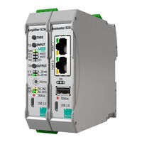
9251 PROFINET Series
User Manuals: Burster 9251 PROFINET Series Controller
Manuals and User Guides for Burster 9251 PROFINET Series Controller. We have
3
Burster 9251 PROFINET Series Controller manuals available for free PDF download: Operation Manual
Burster 9251 PROFINET Series Operation Manual (122 pages)
Fieldbus controller
Brand:
Burster
| Category:
Controller
| Size: 4 MB
Table of Contents
Table of Contents
3
Introduction
8
Purpose of this Manual
8
Validity of the Manual
8
Target Group
8
Display of Information
8
Terms Used in the Manual
8
Warranty
8
Safety
10
Applications
10
Intended Use
10
Foreseeable Misuse
10
Restrictions on Use
10
Limitation of Liability
11
Representation of Hazards
11
Pictograms
12
Symbols on the Controller
12
Requirements for Personnel
12
Residual Hazards
13
Description
14
Functional Scope
14
Block Diagram and Potentials
15
Versions
15
Power Supply
15
Suitable Sensors
16
Automatic Sensor Recognition of Burster TEDS
16
Error Indicators
17
Unpacking/Contents of Pack/Storage
17
Unpacking
17
Contents of Pack
17
Storage
18
Installation
18
Removal
18
Controls and Connections
19
Front View
19
Connection Assignment/Pin Assignment
20
Fieldbus Status Indicator
21
Leds
21
Status LED (Normal Operation)
21
TARE LED and Burster TEDS LED
22
Grounding and Shielding
22
Compatible Sensors/Inputs
22
Full-Bridge Strain Gage Sensors
22
Potentiometric Sensors
23
Voltage Measurement/Transmitters with Voltage Output
23
Reading in Burster TEDS
23
MIN and MAX Values
23
Connections
24
Connecting Strain Gage Sensors
24
Connecting Potentiometric Sensors
26
Connecting Transmitters with Voltage Output
26
Burster TEDS Connection
27
Micro-USB Port for Configuration
27
Device Configuration
28
Digivision Installation
28
Device List
28
Device Settings
29
Device Settings
30
Device Settings - Limit Values
31
Configuration of Digital Inputs
33
Device Settings - Properties
34
Calibration of the Controller with Sensors
35
Calibration with Strain Gage Sensors
35
Calibration with Physical Variable by the Teach-In Method
36
Calibration Using the Test and Calibration Certificate
40
Calibration with Potentiometric Displacement Sensors with Teach-In Method
44
Calibration with Transmitters or Sensors with Standard Signal Output
48
Calibration with Transmitters with Voltage Output by Teach-In Method
48
Calibration Using the Test and Calibration Certificate
51
Profinet
54
Port Identification
55
Planning a PROFINET Network
55
PROFINET Fieldbus-Specific LED Functions
56
Cyclical Data Transmission from the 9251 Fieldbus Controller to the Control System
57
Data Packets for Data Transmission from the 9251 Fieldbus Controller to the Control System Using the "Short" Method
58
Data Packets for Data Transmission from the 9251 Fieldbus Controller to the Control System Using the "Extended" Method
60
Complete Data Protocol for Data Transmission from the 9251 Fieldbus Controller to the Control System Using the "Short" Method
62
Data Protocol for Data Transmission from the 9250 Instrumentation Amplifier to the Control System Using the "Short" Method
63
Data Protocol for Data Transmission from the 9251 Fieldbus Controller to the Control System Using the "Extended" Method
64
Data Protocol for Data Transmission from the 9250 Instrumentation Amplifier to the Control System Using the "Extended" Method
66
Cyclical Data Transmission from the Control System to the 9251 Fieldbus Controller
68
Controlling the Device Functions
68
Data Protocol of Cyclical Data for Data Transmission from the Control System to the 9251 Fieldbus Controller
69
Data Protocol of Cyclical Data for Data Transmission from the Control System to the 9250 Instrumentation Amplifier
71
Acyclical Data
72
Data Protocol of Acyclical Data of 9251 Fieldbus Controller
72
Data Protocol of Acyclical Data of 9250 Instrumentation Amplifier
73
Ethercat
74
Port Identification
75
Ethercat Fieldbus-Specific LED Functions
75
Ethercat PDO - Process Data Objects
77
Overview of Data Packets for Data Transmission from the 9251 Fieldbus Controller to the Control System
78
Data Protocol for Data Transmission from the 9251 Fieldbus Controller to the Control System
80
Data Protocol for Data Transmission from the 9250 Instrumentation Amplifier to the Control System
82
Data Protocol for Data Transmission from the Control System to the 9251 Fieldbus Controller
84
Data Protocol for Data Transmission from the Control System to the 9250 Instrumentation Amplifier
85
Ethercat SDO - Service Data Objects
86
Acyclical Data of 9251 Fieldbus Controller, Channel 1
87
Acyclical Data of 9250 Instrumentation Amplifier, Channel 2
88
Acyclical Data of 9250 Instrumentation Amplifier, Channel 3
89
Acyclical Data of 9250 Instrumentation Amplifier, Channel 4
90
Acyclical Data of 9250 Instrumentation Amplifier, Channel 5
91
Acyclical Data of 9250 Instrumentation Amplifier, Channel 6
92
Acyclical Data of 9250 Instrumentation Amplifier, Channel 7
93
Acyclical Data of 9250 Instrumentation Amplifier, Channel 8
94
Acyclical Data of 9250 Instrumentation Amplifier, Channel 9
95
Ethercat Error Codes
96
Ethernet/Ip
97
Port Identification
98
Ethernet/Ip Fieldbus-Specific LED Functions
98
General Information on Ethernet/Ip Data Transmission
99
EDS File
100
Data Conversion
101
Description of the Data Formats in this Operation Manual
101
Dealing with Problems that Occur When Reading Floating Point Numbers
101
PLC Outputs - Data Transmission from the Adapter (9251) to the Scanner (Control System)
102
Introduction
102
Data Protocol for Cyclical Data Transmission from the Controller to the Scanner
102
Data Protocol for Cyclical Data Transmission from the 9250 Instrumentation Amplifier to the Scanner
103
PLC Inputs - Transmission from the Scanner (Control System) to the Adapter (9251)
103
Data Protocol for Cyclical Data Transmission from the Scanner to the 9250 Instrumentation Amplifier
104
Unconnected Explicit Messaging (Acyclical Services)
105
Acyclical Data of 9251 Fieldbus Controller, Channel 1
106
Acyclical Data of 9250 Instrumentation Amplifier, Channel 2
107
Acyclical Data of 9250 Instrumentation Amplifier, Channel 3
108
Acyclical Data of 9250 Instrumentation Amplifier, Channel 4
109
Acyclical Data of 9250 Instrumentation Amplifier, Channel 5
110
Acyclical Data of 9250 Instrumentation Amplifier, Channel 6
111
Acyclical Data of 9250 Instrumentation Amplifier, Channel 7
112
Acyclical Data of 9250 Instrumentation Amplifier, Channel 8
113
Acyclical Data of 9250 Instrumentation Amplifier, Channel 9
114
Ethernet/Ip Error Codes
115
Cleaning
116
Technical Data
117
Operating Conditions
117
Electromagnetic Compatibility
117
Interference Immunity
117
Interference Emission
117
Accessories
118
Customer Service
118
Customer Service Department
118
Contact Person
118
Service Offering for the 9251 Fieldbus Controller
118
Disposal
119
Declaration of Conformity
120
Advertisement
Burster 9251 PROFINET Series Operation Manual (47 pages)
Fieldbus controller
Brand:
Burster
| Category:
Controller
| Size: 2 MB
Table of Contents
Table of Contents
4
1 For Your Safety
7
Symbols Used in the Operating Manual
7
Signal Words
7
Pictograms
8
Symbols on the 9251 Fieldbus Controller
8
Conventions Used in the Operating Manual
8
2 Introduction
9
Intended Use
9
Customer Service
9
Customer Service Department
9
Contact Person
10
Download the Test Certificate
10
Ambient Conditions
10
Storage Conditions
10
Operating Conditions
10
Restrictions on Use
11
Cleaning
11
Personnel
11
Contents of Pack
11
Unpacking
12
Warranty
12
Conversions and Modifications
12
3 Device Concept
13
Functional Scope
13
Block Diagram and Potentials
13
Versions
14
Power Supply
14
Available Sensors (Optional)
14
Sensor Technologies (Optional)
14
Error Indicators
14
4 Controls and Connections
15
Front View
15
Terminal Assignment / Pin Assignment
16
Fieldbus Status Indicator
16
Leds
17
Status LED (Normal Operation)
17
Grounding and Shielding
18
Compatible Sensors / Inputs
18
Voltage Measurement / Transmitter with Voltage Output (Optional)
18
PLC Inputs
18
PLC Outputs
19
4.10 Micro-USB Port for Configuration
19
4.11 USB Host
19
5 Using the Instrument for the First Time
20
Installation/Removal
20
6 Profinet
21
Port Identification
21
Planning a PROFINET Network
22
PROFINET Fieldbus-Specific LED Functions
22
Cyclical Data Transmission from the 9251 Fieldbus Controller to the Control System
23
Data Packets for Data Transmission from the 9251 Fieldbus Controller to the Control System Using the "Short" Method
24
Data Packets for Data Transmission from the 9251 Fieldbus Controller to the Control System Using the "Extended" Method
25
Complete Data Protocol for Data Transmission from the 9251 Fieldbus Controller to the Control System Using the "Short" Method
26
Data Protocol for Data Transmission from the 9250 Instrumentation Amplifier to the Control System Using the "Short" Method
26
Data Protocol for Data Transmission from the 9251 Fieldbus Controller to the Control System Using the "Extended" Method
27
Data Protocol for Data Transmission from the 9250 Instrumentation Amplifier to the Control System Using the "Extended" Method
28
Cyclical Data Transmission from the Control System to the 9251 Fieldbus Controller
29
Controlling the Device Functions
29
Data Protocol Cyclical Data for Data Transmission from the Control System to the 9251 Fieldbus Controller
29
Data Protocol Cyclical Data for Data Transmission from the Control System to the 9250 Instrumentation Amplifier
30
Acyclical Data
30
Data Protocol Acyclical Data 9251 Fieldbus Controller
31
Data Protocol Acyclical Data 9250 Instrumentation Amplifier
31
7 Ethercat
32
Port Identification
33
Ethercat Fieldbus-Specific LED Functions
33
Ethercat PDO - Process Data Objects
34
Overview of Data Packets, Data Transmission from the 9251 Fieldbus Controller to the Control System
34
Data Protocol for Data Transmission from the 9251 Fieldbus Controller to the Control System
35
Data Protocol for Data Transmission from the 9250 Instrumentation Amplifier to the Control System
36
Data Protocol for Data Transmission from the Control System to the 9251 Fieldbus Controller
37
Data Protocol for Data Transmission from the Control System to the 9250 Instrumentation Amplifier
38
Ethercat SDO - Service Data Objects
39
Acyclical Data 9251 Fieldbus Controller
39
Acyclical Data 9250 Instrumentation Amplifier Module 1
39
Acyclical Data 9250 Instrumentation Amplifier Module 2
40
Acyclical Data 9250 Instrumentation Amplifier Module 3
40
Acyclical Data 9250 Instrumentation Amplifier Module 4
41
Acyclical Data 9250 Instrumentation Amplifier Module 5
41
Acyclical Data 9250 Instrumentation Amplifier Module 6
41
Acyclical Data 9250 Instrumentation Amplifier Module 7
42
Acyclical Data 9250 Instrumentation Amplifier Module 8
42
Ethercat Error Codes
43
8 Service Offering for the 9251 Fieldbus Controller
44
9 Technical Data
45
Electromagnetic Compatibility
45
Interference Immunity
45
Interference Emission
45
10 Accessories Available
46
11 Disposal
47
Burster 9251 PROFINET Series Operation Manual (22 pages)
Fieldbus-Controller
Brand:
Burster
| Category:
Controller
| Size: 1 MB
Table of Contents
Table of Contents
2
Introduction
3
Creating New Project
4
Installation of GSDML Files
6
Creation of Network Connections
7
Create a Sample Program
11
Further Examples
17
Reading of 'String' Data Types
18
Read and Write of 'Real' Data Types
21
Advertisement
Advertisement
Related Products
Burster 9251-VXX03
Burster 9250
Burster 9235
Burster 9221 Series
Burster 9221 IP 230
Burster 9221 IP 65
Burster 9243
Burster 9205
Burster 9206
Burster 9210
Burster Categories
Measuring Instruments
Accessories
Test Equipment
Control Unit
Security Sensors
More Burster Manuals
Login
Sign In
OR
Sign in with Facebook
Sign in with Google
Upload manual
Upload from disk
Upload from URL