
Summary of Contents for Technifor XM700
- Page 1 OPERATING AND MAINTENANCE MANUAL XM700 MICRO-PERCUSSION MARKING MACHINE portable version Gravotech reserves all rights to modify its products. www.technifor.com This document is non contractual.
-
Page 2: Table Of Contents
1. Description of the machine ........................7 2. Technical specifications ......................... 8 3. Physical characteristics .......................... 8 4. XM700 dimensional drawing ........................9 5. List of accessories available upon request ................... 10 Dimensional drawing: Side handle ....................11 Dimensional drawing: Ventilator ...................... 12 Dimensional drawing: Marking area lighting ................... -
Page 3: A - Introduction
Introduction Technifor is a used, pending and/or registered trademark belonging to Gravotech Group or one of its subsidiaries. Thank you for choosing XM700 Technifor. For more information on products, visit www.technifor.com website. www.gravotech.com 1. Unpacking • machine: XM700 • 1 power supply •... -
Page 4: Power
Manufacturer, Gravotech Marking SAS - 466 rue des Mercières - 69140 Rillieux-la-Pape - France (head office) declares that the following equipment: - description: marking machine - model: XM700 is compliant with the following European directives and harmonised standards: European directives that require a CE marking •... - Page 5 Introduction Other European directives Equipment is compliant with the following European directives: • Directive 2006/66/EC of the European Parliament and of the Council of 6 September 2006 on batteries and accumulators and waste batteries and accumulators. • amended Directive 2002/96/EC of the European Parliament and of the Council of 27 January 2003 on waste electrical and electronic equipment (WEEE).
-
Page 6: Work Station Safety
Instructions for use and warranty limitations This equipment is designed to mark material using Technifor electromagnetic styli only. Any other use, or the use of styli other than those provided by Technifor is not recommended. Technifor will not be held responsible for the results. -
Page 7: B - Operating Instructions For The Machine
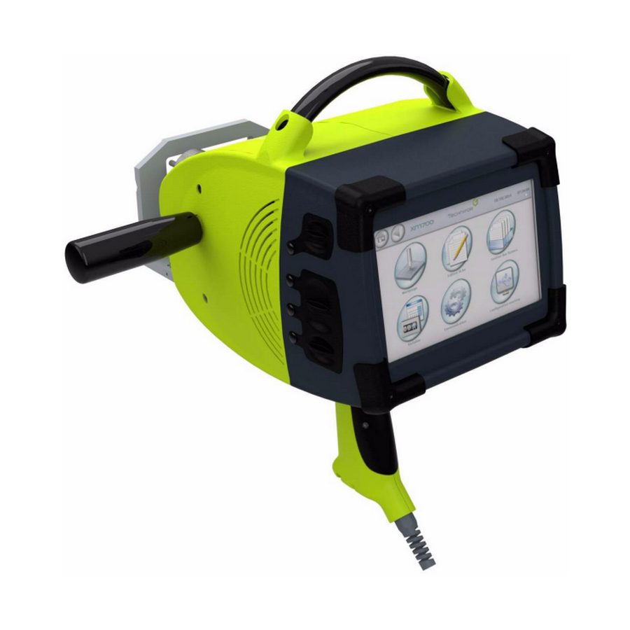
Operating instructions for the machine 1. Description of the machine The XM700 is a numerically controlled micro-percussion marking machine. This machine works by moving the stylus along the X and Y axes of a grid. The control electronics and the screen are integrated. Together with the power unit, they form a compact and portable assembly. -
Page 8: Technical Specifications
Operating instructions for the machine 2. Technical specifications • fonts available: - continuous action (font 0) - dot by dot (font 1-3) - size: from 0.5 mm (0.02 in) to 45 mm (1.772 in) with increments of 0.1 mm (5/1000 in) - characters: those included in the basic multilingual diagram of the Unicode standard (ISO 10646) •... -
Page 9: Xm700 Dimensional Drawing
Operating instructions for the machine 4. XM700 dimensional drawing Ref. 72523 - XM700_en_B 9/23... -
Page 10: List Of Accessories Available Upon Request
Operating instructions for the machine 5. List of accessories available upon request The accessories mentioned below are available upon request. M-Travel Ref. 73289 Wheeled carry case containing protective foam, which protects the machine and its accessories Column stand Ref. 73118 •... - Page 11 Operating instructions for the machine Lifting ring Ref. 52307 Additional lifting ring to replace a lost ring Touch screen pen Ref. 64588 Touch screen pen Ventilator Ref. 73066 Used to cool the stylus when running at a very high operating factor. Marking area lighting Ref.
-
Page 12: Dimensional Drawing: Side Handle
Operating instructions for the machine Dimensional drawing: Side handle Dimensional drawing: Ventilator Dimensional drawing: Marking area lighting Ref. 72523 - XM700_en_B 12/23... -
Page 13: C - Installation
Installation 1. Coordinate system The coordinate system used in our machines is shown in the following diagram. The origin position is defined by the dimensions of 5.5 mm (0.217 in) (dimensions between the point axis and the edge of the window). Tolerance: +/- 1 mm (0.039 in) Coordinate system 1 : Stylus: origin 2 : X axis - Travel distance 80 mm (3.15 in) - Page 14 Installation To bring the point close to the part, follow the foot adjustment procedure below: 1 : Screws 2 : Supporting leg Loosen the screws until the foot slides (4 hex spanner). 3 : Tooling plate (example: 2 mm (0.079 in) thickness) 4 : Non-slip surface 5 : Slide gauge: depth gauge...
-
Page 15: Using The T07 Program / Using The Touch Screen
Installation Disregard for the conditions listed below will void the warranty. The distance L must be between 3 mm (0.118 in) and 6.5 mm (0.256 in). Optimum adjustment distance: 6 mm (0.236 in) Minimum adjustment distance: 3 mm (0.118 in) Maximum adjustment distance: 6.5 mm (0.256 in) 1 : Screws Screw the 2 screws. -
Page 16: Battery - Charger
Installation Turn on the machine by flipping the switch to the "ON" position (under the handle). After disconnecting from the power supply using the switch, wait for 5 seconds before resetting to the ON position. Otherwise the machine will not start up (black screen). 4. -
Page 17: Recommendations
Installation Recommendations • Do not dismantle, open or destroy the battery. • Keep the battery away from heat sources and fire. Do not store in full sunlight. • Do not short-circuit the battery. • Do not remove the battery from its packaging until you are ready to use it. •... -
Page 18: D - Preventive Maintenance
Preventive maintenance The maintenance operations listed here are intended as a guideline, and should be implemented upon reception of the material. In a highly polluted environment, these operations may need to be performed more frequently. Unplug the power supply plug before beginning any cleaning or maintenance operation (power cable or battery cable). -
Page 19: Every Year
Preventive maintenance 2. Every year Have the marking head serviced by Gravotech. This operation includes: • complete dismantling of the machine • cleaning of the mechanical elements • replacement of the point and its spring • verification of the condition of the motors and the belt •... -
Page 20: E - Wearing And Spare Parts
Wearing and spare parts Please give the item codes with your order to speed processing. 1. Wearing parts Styli: Reference Description 73067 Stylus M2S Points: Reference Description 73508 Carbide point 60° radius 0.2 mm (0.008 in) for stylus M2S 73533 Carbide point 90°... -
Page 21: F - Emitted Vibration Level
• spectrum analyser M+P international Vib Pilot VP8 • accelerometer PCB Piezotronics 356A32 Material used for marking: • XM700 handheld machine • power supply or battery (standard) • magnetic tray to hold the plate The assembly is placed on a concrete floor. -
Page 22: G - Noise Emission Of The Machine
• Cal 01 calibrator, # 40141 Material used for marking: • type XM700 machine mounted on a column stand • one electronic command unit The unit is placed on a wood workbench in a workshop where the background noise level is negligible compared with the noise emitted by the machine. -
Page 23: H - Appendix
E-mail: infotechnifor@in.gravotech.com SOUTH AFRICA BRAZIL MEXICO GravoTech (Pty) Ltd Technifor Pictor Ltda GravoTech S. DE R.L DE C.V Unit 8 Rutland Mews - 30 Main Street Av. Dr. Luis Arrobas Martins, 98 Lago Erne, 246 - Colonia Pensil Eastleigh, 1609 EDENVALE...
Need help?
Do you have a question about the XM700 and is the answer not in the manual?
Questions and answers
The M2S engraving needle tip broke off on my Gravotech XM700 engraving unit. What do I need to order? On the M2S Stylus it has TF24033 M2S 90-2.