Advertisement
QUICK INSTALLATION
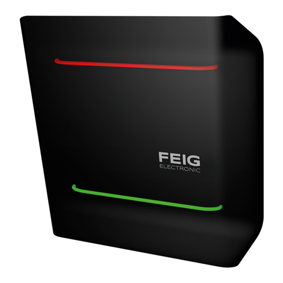
ID MAX.U500i
Scope of Delivery
1 x Vehicle Access Control Reader ID MAX.U500i
1 x M20 cable gland; cable ∅ 6–13 mm; for USB
1 x M20 reduction sealing insert for 1 cable; cable ∅ 4–8 mm
1x M25 slotted reduction sealing insert for 1 cable; cable ∅ 4–6.5 mm
1 x M20 multiple sealing insert for 2 cables; cable ∅ 2–4 mm
1 x M20 multiple sealing insert for 4 cables; cable ∅ 2–4 mm
1 x M16 multiple sealing insert for 2 cables; cable ∅ 2–4 mm
2 x UHF windshield transponder
Required Tools
Slotted screwdriver big
•
Slotted screwdriver small
•
•
Hex key size 5
Available Software
USB driver (when using the USB interface)
•
Access control software myAXXESS Manager (V2.04 or higher)
•
Driver and software can be downloaded from the download area of FEIG under the following link:
https://www.feig.de/en/login
Username:
myAXXESS
Password:
max_reader
M81213-2e-ID-B
Advertisement
Table of Contents

Subscribe to Our Youtube Channel
Summary of Contents for Feig Electronic myAXXESS ID MAX.U500i
- Page 1 QUICK INSTALLATION ID MAX.U500i Scope of Delivery 1 x Vehicle Access Control Reader ID MAX.U500i 1 x M20 cable gland; cable ∅ 6–13 mm; for USB 1 x M20 reduction sealing insert for 1 cable; cable ∅ 4–8 mm 1x M25 slotted reduction sealing insert for 1 cable; cable ∅ 4–6.5 mm 1 x M20 multiple sealing insert for 2 cables;...
- Page 2 IDENTIFICATION ID MAX.U500i Commissioning of the ID MAX.U500i Commissioning of the ID MAX.U500i STEP 1 Attach the ID MAX.U500i to the pole or bollard using the VESA mounting kit. The reader should be aligned at a 45° angle to the lane. For secondary protection the reader should be secured by means of an eye bolt. ...
- Page 3 IDENTIFICATION ID MAX.U500i Teach-In Mode STEP 4 To connect the external electronics, use the potential-free relay output or the potential-free digital output, which is galvanically isolated from the reader electronics. REL1-NO Normally open contact relay 1 OPTO1-OUT-E Digital Output 1 Emitter (–) REL1-COM Changeover contact relay 1 OPTO1-OUT-C...
- Page 4 IDENTIFICATION ID MAX.U500i Safety Instructions NOTE: • In case of power down during activated Teach-In Mode all temporarily stored authorizations are lost and have to be read again. • In case of power down during deactivation of the Teach-In Mode (after pressing the push button T1 twice within short time the second time) all authorizations stored in the reader may be lost.


Need help?
Do you have a question about the myAXXESS ID MAX.U500i and is the answer not in the manual?
Questions and answers