
Related Manuals for Feig Electronic ID ISC.MR102


Summary of Contents for Feig Electronic ID ISC.MR102
- Page 1 INSTALLATION MANUAL ID ISC.MR102 For all variants final – public (B) 2018-01-18 – M01210-6e-ID.doc...
- Page 2 FEIG ELECTRONIC call explicit attention that devices which are subject of this document are not designed with components and testing methods for a level of reliability suitable for use in or in connection with surgical implants or as critical components in any life support systems whose failure to perform can reasonably be expected to cause significant injury to a human.
-
Page 3: Table Of Contents
Power supply .......................... 11 Power supply via X1 ......................11 Power supply via PoE (Power over Ethernet) on X4 (ID ISC.MR102-PoE) ......12 Power supply and interface connection on X2 (ID ISC.MR102-A) ........13 RS232 Interface (ID ISC.MR102-A) ..................13 Ethernet-Interface on X2 (10/100Tbase) ................ - Page 4 Identification Installation ID ISC.MR102 Technical Data Radio Approvals Europe (CE) ..........................18 Europe (CE) ..........................19 USA (FCC) and Canada (IC) ....................20 UL Approval - USA and Canada Annex Accessories ..........................23 Wall mounting kit ID ISC.MS.MR/PR-A ................24 Serial data cable ID CAB.RS-A ....................
- Page 5 Identification Installation ID ISC.MR102 Safety Instructions / Warning - Read before start-up ! The device may only be used for the purpose intended by the manufacturer. The operation manual should be kept readily available at all times for each user.
-
Page 6: Performance Features Of The Readers
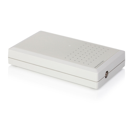
The Reader ID ISC.MR102 is designed for reading passive data carriers, so-called „Smart Labels“ at an operating frequency of 13.56 MHz. The ID ISC.MR102 is suitable for all applications in which moderate reading distances are re- quired. Also required is an external antenna connected to the Reader. -
Page 7: Assembly And Wiring
Identification Installation ID ISC.MR102 Assembly and Wiring Housing versions The Reader is designed for an office environment. It can be wall-mounted, in this case the wall- mount kit should be ordered separately. (see Appendix: Wall mounting kit ID ISC.MS.MR/PR-A) Notes: ... -
Page 8: Module Version
Identification Installation ID ISC.MR102 Module version This reader version has been designed for mounting in other equipment. Notes: The distance between two readers of the same type should not fall below 4m. Before any installation the intended position of the reader should be tested for it´s suit- ability. -
Page 9: Connections
Identification Installation ID ISC.MR102 Connections Depending on the reader variant different connectors are available. Figure 3: Connection overview displays the arrangement and the Table 2: Connectors shows which connector can be used for the different interface cable. ID ISC.MR102-A ID ISC.MR102-PoE ID ISC.MR102... -
Page 10: Antenna Terminal Ant 1
Identification Installation ID ISC.MR102 Antenna terminal ANT 1 A SMA socket is provided on the circuit board for connecting the external antenna. The maximum tightening torque for the SMA socket is 0.45 Nm. Caution: Higher tightening torque will damage the connector. -
Page 11: Power Supply
Identification Installation ID ISC.MR102 Power supply Power supply via X1 The reader has to supplied by a limited power supply (e.g. NEC Class 2/LPS power supply) ac- cording IEC EN 60950, only. Connect the 12-24 V DC/ supply voltage to socket X1 on the circuit board. -
Page 12: Power Supply Via Poe (Power Over Ethernet) On X4 (Id Isc.mr102-Poe)
Installation ID ISC.MR102 Power supply via PoE (Power over Ethernet) on X4 (ID ISC.MR102-PoE) Optional the reader (only MR102-PoE) can be powered via the LAN connector on X4 with the use of a PoE „Power over Ethernet“ power supply according to IEEE802.3af*, Class2 (6,49 Watt). -
Page 13: Power Supply And Interface Connection On X2 (Id Isc.mr102-A)
Identification Installation ID ISC.MR102 Power supply and interface connection on X2 (ID ISC.MR102-A) For the power supply connection and the connection of the asynchronous interface RS232 / 485 the reader provides a 9-pin D-Subminiature female connector. (See also Connections). Interface Power supply 1;4;6;8... -
Page 14: Ethernet-Interface On X2 (10/100Tbase)
Identification Installation ID ISC.MR102 Ethernet-Interface on X2 (10/100Tbase) The Reader has an integrated 10 / 100 base-T network port for an RJ-45. Connection is made on X2 and has an automatic “Crossover Detection” according to the 100BASE-T Standard. With structured cabling CAT 5 cables should be used. This ensures a reliable operation at 10 Mbps or 100 Mbps. -
Page 15: Control And Display Elements Led
Identification Installation ID ISC.MR102 Control and display elements LED The Reader’s LED can be configured through software. The following Table 10 shows the default setting. Abbreviation Description "RUN " LED green Turns on when the Reader is ready „LABEL“ Turns on when a transponder is detected. - Page 16 Degree of Protection IP 30 Color similar RAL 9018 (papyrus white) Electrical Data Supply voltage – ID ISC.MR102-A/-B/-USB 12 …24V DC/ – ID ISC.MR102-PoE 12 …24V DC/ or PoE Power consumption max. 9 W Operating frequency 13,56 MHz ...
- Page 17 Identification Installation ID ISC.MR102 Functional Properties Protocol Modes - FEIG ISO HOST - Scan Mode - ISO15693, ISO18000-3 Mode 1 Supported transponders (EM HF ISO Chips, Fujitsu HF ISO Chips, KSW Sensor Chips, IDS Sensor Chips, Infineon my-d, NXP I-Code, STM LRI ISO...
-
Page 18: Radio Approvals
ID ISC.MR102 Radio Approvals Europe (CE) Hereby, FEIG ELECTRONIC GmbH declares that the radio equipment type ID CPR74 is in com- pliance with Directive 2014/53/EU. The full text of the EU declaration of conformity is available at the following internet address: http://www.feig.de/en/downloads-support/declarations-of-conformity.html... -
Page 19: Europe (Ce)
Identification Installation ID ISC.MR102 Europe (CE) FEIG ELECTRONIC GmbH Page 19 of 26 M01210-6e-ID.doc... -
Page 20: Usa (Fcc) And Canada (Ic)
Warning: Changes or modification made to this equipment not expressly approved by FEIG ELECTRONIC GmbH may void the FCC authorization to operate this equipment. FEIG ELECTRONIC GmbH Page 20 of 26... - Page 21 Identification Installation ID ISC.MR102 Installation with FCC / IC Approval: FCC-/IC-NOTICE: To comply with FCC Part 15 Rules in the United States / with IC Radio Stand- ards in Canada, the system must be professionally installed to ensure compliance with the Part 15 certification / IC certification.
-
Page 22: Ul Approval - Usa And Canada
Installation ID ISC.MR102 Identification UL Approval - USA and Canada The following UL label position is on the back side of the reader. ID ISC.MR102-A ID ISC.MRM102-A ID ISC.MR102-PoE ID ISC.MR102-USB ID ISC.MRM102-USB FEIG ELECTRONIC GmbH Page 22 of 26... -
Page 23: Annex
Identification Installation ID ISC.MR102 Annex Accessories The following accessories are available for the Reader. Article No. Name Description Power Supply 100 - 240V AC Input Voltage, (Continental European Plug), ID NET.12V-B-EU 1688.002.00 with angular DC Plug 2,5mm*5,5mm Power Supply Unit 12V Output: 12 V DC/ ;... -
Page 24: Wall Mounting Kit Id Isc.ms.mr/Pr-A
Identification Installation ID ISC.MR102 Wall mounting kit ID ISC.MS.MR/PR-A The wall mounting kit can be used to attach the Reader to a flat surface. Remove the screws from the back side of the Reader. Attach the individual wall hangers using the screws supplied with the mounting kit. -
Page 25: Serial Data Cable Id Cab.rs-A
Identification Installation ID ISC.MR102 Serial data cable ID CAB.RS-A Reader D-Sub 9pol. male D-Sub 9pol. female DC Jack 2,5 x 5,5mm (outside) (inside) Figure 8: Serial data cable with supply voltage connection FEIG ELECTRONIC GmbH Page 25 of 26 M01210-6e-ID.doc... -
Page 26: Antenna
Identification Installation ID ISC.MR102 Antenna Figure 10: ID ISC.ANT310/310 Figure 9: ID ISC.ANT340/240 Figure 11: ID ISC.ANTS370/270 Figure 12: ID ISC.ANTH200/200 FEIG ELECTRONIC GmbH Page 26 of 26 M01210-6e-ID.doc...
Need help?
Do you have a question about the ID ISC.MR102 and is the answer not in the manual?
Questions and answers