Advertisement
Sicherheitshinweise
DE
Bedienungsanleitung
PL
Wskazówki dotyczące bezpieczeństwa
Instrukcja obsługi
Avvisi di sicurezza
IT
Istruzioni per l' uso modello
GB
1904046 | 11-2018
DT104-28
Mod. 2014
Glühdraht-Schneidegerät
DE
Urządzenie do cięcia drutem
PL
oporowym
IT
Trancia a filo incandescente
GB
Heated Wire Cutting Device
2
3-9
2
3-9
2
3-9
2
3-9
DT104-28
1
Advertisement
Table of Contents

Related Manuals for SPEWE DT104-28


Summary of Contents for SPEWE DT104-28
- Page 1 DT104-28 Mod. 2014 Glühdraht-Schneidegerät Urządzenie do cięcia drutem oporowym Trancia a filo incandescente Heated Wire Cutting Device Sicherheitshinweise Bedienungsanleitung Wskazówki dotyczące bezpieczeństwa Instrukcja obsługi Avvisi di sicurezza Istruzioni per l’ uso modello Safety Instructions Operating Instructions DT104-28 1904046 | 11-2018...
- Page 2 Przykrój: Termicznie, zasilanie prądem: 230V / 50 Hz Corredo di fornitura: Trancia a filo incandescente modello DT104-28 con alimentatore integrato, istruzioni per l’uso, valigetta per il trasporto e la custodia. Optionale: Supporto per parapetto | supporto per il montaggio libero Dati tecnici: Lunghezza di taglio: 104 cm| Profondità...
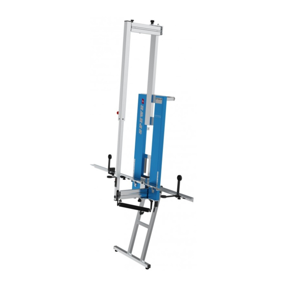
- Page 3 The stand, angled forwards, allows the device to utilise the space between the wall and frame retainer. This results in enhanced access at the frame. Fig. 3 DT104-28 1904046 | 11-2018...
- Page 4 Pivot the bearing rail [9+10]. Fold out the bearing supports [11] beneath the bearing rails. These can be shifted if necessary. To do so, loosen the knurled screw [12]. Fold out the bearing supports [13] on both sides. Fig. 6 Fig. 7 DT104-28 1904046 | 11-2018...
- Page 5 (Fig. 11) and tighten the knurled screw [14]. Reducing the cutting length: Loosen the knurled screw [14+15+16], retract the cutting bracket, tighten the knurled screw [15+16], tension the wire spool (Fig. 11) and tighten the knurled screw [14]. Fig. 10 Fig. 11 DT104-28 1904046 | 11-2018...
- Page 6 [25] in place. Separation cut: Draw the cutting bracket [20] to the desired height and tighten the fixing screw [26] top and bottom. Subsequently cut through the panel. After cutting, preferably switch the cutting device off. Fig. 13 DT104-28 1904046 | 11-2018...
- Page 7 The wire does not heat up: Clean wire guide rollers [31] top and bottom, as well as contact surfaces [32]. Check that the device is fully extended or retracted. Check that the knurled screw [33] is securely seated. Fig. 15 DT104-28 1904046 | 11-2018...
- Page 8 Disconnect the device from the 230V mains for 30 minutes to allow it to cool down. Never remove the seal sticker [35] or open up the power supply Fig. 16 unit. Repairs must be carried out by a specialist exclusively. filo / Installing New ghtening the Wire DT104-28 1904046 | 11-2018...
Need help?
Do you have a question about the DT104-28 and is the answer not in the manual?
Questions and answers