Table of Contents
Advertisement
Original Issue Date: 12/13
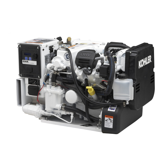
Model: 5/7.5/10EKD and 4/6/8EFKD
Market: Marine
Subject: Seawater Flow Switch Kit GM90489
Introduction
Installation of this kit involves adding a seawater flow
switch and replacing/relocating the seawater pressure
switch with a new switch that provides enhanced
protection for loss or low seawater flow.
Required Tools
The following tools and supplies are needed:
Electrical tape
D
Teflon tape
D
Loctite
R
565 general purpose pipe sealant paste
D
Drill and 3/16 in. drill bit
D
5/16 in. socket, 1/4 in. drive
D
10 mm socket, 1/4 in. drive
D
15 mm open end wrench
D
13 mm open end wrench
D
3/8 in. open end wrench
D
7/16 in. open end wrench
D
3 in. Phillips screwdriver
D
1/4 in. socket
D
1/4 in. drive ratchet
D
Hose cutter knife
D
Wire cutter
D
Rags
D
Safety Precautions
Observe the following safety precautions while
performing this procedure.
WARNING
Accidental starting.
Can cause severe injury or death.
Disconnect the battery cables before
working
on
Remove the negative (--) lead first
when disconnecting the battery.
Reconnect the negative (--) lead last
when reconnecting the battery.
INSTALLATION INSTRUCTIONS
the
generator
set.
Disabling the generator set.
cause severe injury or death.
generator set or connected equipment, disable the generator
set as follows: (1) Move the generator set master switch to the
OFF position. (2) Disconnect the power to the battery charger.
(3) Remove the battery cables, negative (--) lead first.
Reconnect the negative (--) lead last when reconnecting the
battery. Follow these precautions to prevent starting of the
generator set by an automatic transfer switch, remote
start/stop switch, or engine start command from a remote
computer.
WARNING
Hazardous voltage.
Can cause severe injury or death.
Operate the generator set only when
all guards and electrical enclosures
are in place.
Testing live electrical circuits.
current can cause severe injury or death. Have trained and
qualified personnel take diagnostic measurements of live
circuits. Use adequately rated test equipment with electrically
insulated probes and follow the instructions of the test
equipment manufacturer when performing voltage tests.
Observe the following precautions when performing voltage
tests: (1) Remove all jewelry. (2) Stand on a dry, approved
electrically insulated mat. (3) Do not touch the enclosure or
components inside the enclosure. (4) Be prepared for the
system to operate automatically.
(600 volts and under)
TT-1617 12/13
Accidental starting can
Before working on the
Moving parts.
Hazardous voltage or
Advertisement
Table of Contents

Related Manuals for Kohler 5EKD


Summary of Contents for Kohler 5EKD
- Page 1 TT-1617 12/13 INSTALLATION INSTRUCTIONS Original Issue Date: 12/13 Model: 5/7.5/10EKD and 4/6/8EFKD Market: Marine Subject: Seawater Flow Switch Kit GM90489 Introduction Disabling the generator set. Accidental starting can cause severe injury or death. Before working on the generator set or connected equipment, disable the generator Installation of this kit involves adding a seawater flow set as follows: (1) Move the generator set master switch to the switch and replacing/relocating the seawater pressure...
- Page 2 Procedure Engine-End View Remove the generator set from service. Push the generator set power button OFF. Disconnect power to the battery charger, if equipped. Disconnect the generator set engine starting battery, negative (--) lead first. GM55219C Remove the sound shield, if equipped. 1.
- Page 3 See Figure 8. cap bolt and temperature switch and save the temperature switch for the possible return to Side View of Exhaust Manifold Kohler Power Systems. Discard the hex cap bolt (X-6238-2). Remove, replace, and relocate the seawater pressure switch.
- Page 4 Route the relay end of the wiring harness Nonservice Side (GM90471) behind the fuel pump, behind the sound shield ADC II panel (if equipped), and up into the bottom of the junction box. See Figure 9. Note: If routing the harness as outlined in Step 5.1 does not work, pull the harness through from the inside of the junction box and leave the relay base end of the...
- Page 5 Install the relay in the junction box. Use a 5/16 in. socket, 1/4 in. drive to remove the junction box cover. Place a rag inside the junction box to catch any filings. Drill a 3/16 in. hole at the location shown in Figure 11.
- Page 6 Install the flow switch. For Units With a Siphon Break: For Units Without a Siphon Break: 7.2.1 Remove the hose located between the heat exchanger end cap and the hose Note: Proceed to Section 7.2 for units with a connector. See Figure 14. siphon break.
- Page 7 test validates the seawater flow switch operation and wiring. 8.2.4 Reset the controller. See the operation manual for reset procedure. 8.2.5 Reconnect the wire to the seawater pressure switch that was removed in Step 8.2.1. Seawater Pressure Switch Validation Test 8.3.1 Pull the newly installed relay (P26) from its base.
- Page 8 Procedure to Clean Seawater Flow Switch Check and clean the seawater flow switch according to the Service Schedule in Section 10. Push the generator set power button OFF. Disconnect power to the battery charger, if equipped. Disconnect the generator set engine starting battery, negative (--) lead first.
- Page 9 10. Service Schedule After Every Every Every Before 50 Hr or 100 Hr or 300 Hr or 500 Hr or Starting Perform Service at Intervals Indicated (X) 1 Month 3 Months 6 Months Yearly Fuel System Check the fuel level and fill as necessary Check fuel lines and replace as necessary *[ Replace the fuel filter *[ Lubrication System...
- Page 10 11. Wiring Diagrams GM90655A-- Figure 17 Point-to-Point Wiring Diagram (Sheet 1 of 2) TT-1617 12/13...
- Page 11 GM90655B-- Figure 18 Point-to-Point Wiring Diagram (Sheet 2 of 2) TT-1617 12/13...
- Page 12 ADV8631A-- Figure 19 Schematic Wiring Diagram (Sheet 1 of 1) TT-1617 12/13...
- Page 13 Notes TT-1617 12/13...
- Page 14 Notes TT-1617 12/13...
- Page 15 Notes TT-1617 12/13...
- Page 16 Singapore 619159 KOHLERPower.com Phone (65) 6264-6422, Fax (65) 6264-6455 Availability is subject to change without notice. Kohler Co. reserves the right to change the design or specifications without notice and without any obligation or liability whatsoever. Contact your local Kohlerr generator set distributor for availability.
Need help?
Do you have a question about the 5EKD and is the answer not in the manual?
Questions and answers