Table of Contents
Advertisement
Original Issue Date: 11/09
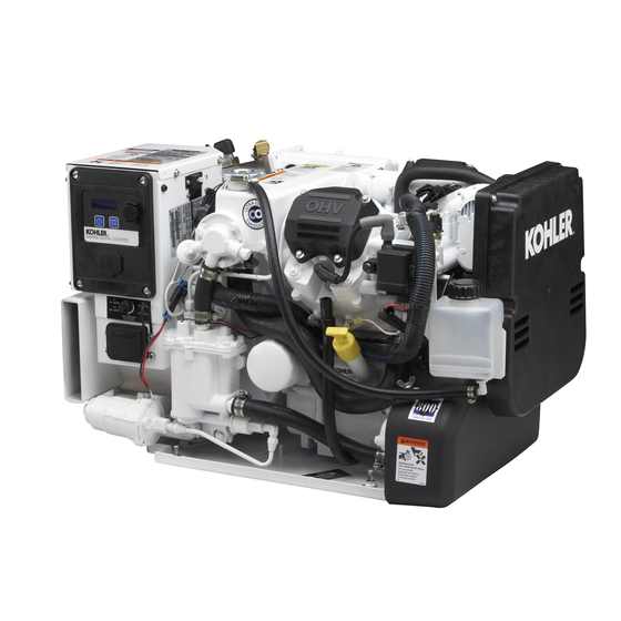
Model: 5/7.5/10EKD and 4/6/8EFKD
Market: Marine
Subject: Siphon Break Kit GM60007-KP1 for Sound Shielded Units
Introduction
Use these instructions to install a siphon break on
sound-shielded generator sets.
prevents seawater entry into the generator set engine
when the engine exhaust manifold outlet is less than
230 mm (9 in.) above the waterline of a fully loaded
docked or stationary craft.
Read the entire installation procedure. Perform the
steps in the order shown.
Note: Install this siphon break kit on generator sets
equipped with the sound shield kits specified in
Figure 1. Do not install these siphon break kits on
generator sets without sound shields.
Model
5EKD/4EFKD
7.5EKD/6EFKD
10EKD/8EFKD
Figure 1 Sound Shield Kits
Safety Precautions
WARNING
Accidental starting.
Can cause severe injury or death.
Disconnect the battery cables before
working
on
Remove the negative (--) lead first
when disconnecting the battery.
Reconnect the negative (--) lead last
when reconnecting the battery.
INSTALLATION INSTRUCTIONS
A siphon break
Factory
Field
Installed Kit
Installed Kit
GM55219-KA1 GM55219-KP1
GM55219-KA2 GM55219-KP2
the
generator
set.
Disabling the generator set.
cause severe injury or death.
generator set or connected equipment, disable the generator
set as follows: (1) Move the generator set master switch to the
OFF position. (2) Disconnect the power to the battery charger.
(3) Remove the battery cables, negative (--) lead first.
Reconnect the negative (--) lead last when reconnecting the
battery. Follow these precautions to prevent starting of the
generator set by an automatic transfer switch, remote
start/stop switch, or engine start command from a remote
computer.
WARNING
Hazardous voltage.
Can cause severe injury or death.
Operate the generator set only when
all guards and electrical enclosures
are in place.
Servicing the generator set when it is operating. Exposed
moving parts can cause severe injury or death. Keep
hands, feet, hair, clothing, and test leads away from the belts
and pulleys when the generator set is running. Replace
guards, screens, and covers before operating the generator
set.
Installation Procedure
1.
Remove the generator set from service.
1.1
Press the start/stop button to stop the generator
set. The engine stops.
1.2
Press the power button to turn off the controller.
1.3
Disconnect the power to the battery charger, if
equipped.
1.4
Disconnect the generator set engine starting
battery, the negative (--) lead first.
TT-1509
4/14a
Accidental starting can
Before working on the
Moving parts.
Advertisement
Table of Contents

Related Manuals for Kohler 5EKD


Summary of Contents for Kohler 5EKD
-
Page 1: Installation Instructions
Factory Field Hazardous voltage. Moving parts. Installed Kit Installed Kit Model Can cause severe injury or death. 5EKD/4EFKD GM55219-KA1 GM55219-KP1 Operate the generator set only when 7.5EKD/6EFKD all guards and electrical enclosures 10EKD/8EFKD GM55219-KA2 GM55219-KP2 are in place. Figure 1 Sound Shield Kits Servicing the generator set when it is operating. - Page 2 Figure 2. secure the hose (X-312-61) to the exhaust catalyst using a hose clamp (X-426-12). See Figure 6. Note: 5/7.5EKD and 4/6EFKD Models: Cut the hose (X-312-61) to fit. Route the hose from the exhaust catalyst to the remaining hole in the sound shield’s exhaust panel.
-
Page 3: Parts List
3.12 Connect clear flexible plastic tubing Inspect the siphon break. (GM34883) to the siphon break cap using a hose Remove the retaining cap and remove the reed clamp (X-426-9) to secure. Route the tubing to a valve for inspection. See Figure 5. convenient location. - Page 4 5. Grommets (X-284-7 qty. 2) Figure 6 Hose Locations Availability is subject to change without notice. Kohler Co. reserves the right to change the design or specifications without notice and without any obligation or liability whatsoever. Contact your local Kohlerr generator set distributor for availability.
Need help?
Do you have a question about the 5EKD and is the answer not in the manual?
Questions and answers